

FENDT Katana 650 Gen3 Workshop Service Manual – PDF DOWNLOAD
DESCRIPTION:
FENDT Katana 650 Gen3 Workshop Service Manual – PDF DOWNLOAD
1.1 Safety instructions
1.1.1 Safety briefing and measures
Important notes on work safety
The statutory accident prevention regulations (available from professional associations or specialist shops) must be observed. These depend on the operating site, operating mode and fuels and lubricants used. Special protective measures dependent on the respective procedures are specified in the corresponding repair guidelines and highlighted
This handbook uses the following safety tips
DANGER:
Indicates an impending dangerous situation that will lead to serious injury or death if not
avoided.
WARNING:
Indicates a potentially dangerous situation that could lead to serious injury or death if not
avoided.
CAUTION:
Indicates a potentially dangerous situation that could lead to minor injury if not avoided.
Please observe the following when carrying out maintenance or service work on the vehicle:
Only the documentation associated with the vehicle (workshop manual and operator’s manual) must be used to complete any pending work.
1. General
- Only trained personnel may operate the vehicle or carry out maintenance work. • Only use qualified specialists to carry out repairs or service work.
- When working underneath the jacked-up vehicle, make sure no one is in the cab. • Relieve pressure on the pressure lines for headers.
- All people should keep clear of a lifted, unsecured load (e.g. tilted cab etc.).
- Never open or remove any safety devices while the engine is running.
- Pressurized fluids (fuel or hydraulic oil) escaping under high pressure can penetrate the skin and cause severe injuries. If this should occur, seek medical advice immediately to avoid the risk of serious infection.
- Keep at a safe distance from hot areas.
- Pressure accumulator and connected pipes are highly pressurized. Only remove and repair in accordance with instructions provided in the workshop manual.
- To avoid eye injury, do not look directly at the surface of the activated radar sensor.
- Dispose of oil, fuel and filters properly!
- Specialist knowledge and special fitting tools are required to fit tires.
- Run the tractor for a short time, then retighten all wheel nuts and bolts and check them regularly. For correct torque values refer to the technical data.
- Before working on the electrical system, always remove the earth strap from the battery. Observe the following when carrying out electric welding. Before performing welding work on the vehicle or mounted equipment, ensure that all battery terminals are disconnected
- Attach the welding appliance’s earth terminal as close to the welding spot as possible.
- Caution is required when dealing with brake fluid and battery acid as these are toxic and corrosive!
- Only use genuine FENDT spare parts.
TABLE OF CONTENTS:
FENDT Katana 650 Gen3 Workshop Service Manual – PDF DOWNLOAD
1 00-000 Entire vehicle system 1-1
11 Safety instructions 1-3
111 Safety briefing and measures 1-3
12 General information 1-6
121 Notes on documentation 1-6
122 Note on hydraulics 1-7
123 Location of the identification plates 1-7
13 Screw connections 1-11
131 Threadlock compound 1-11
132 Hydraulic screw connections 1-12
133 Spanner sizes for globally standard parts 1-15
14 Tightening torques 1-16
141 General tightening instructions 1-16
1411 Tightening torque for screws and bolts with VDA coating 1-16
1412 Tightening torque for screws with a galvanized surface 1-17
1413 Tightening torque for threaded plugs 1-18
1414 Tightening torque for banjo bolts 1-19
1415 Tightening torque for hose clamps 1-20
142 Tightening torques for electrical connections 1-21
15 Fuels and lubricants 1-24
151 Biodiesel 1-24
152 Biodegradable hydraulic oil 1-24
16 Technical specification 1-26
161 Technical data: general for Katana 650 Gen3 1-26
162 Technical specification: Engine 1-28
163 Technical data: Gearbox 1-30
164 Technical data: Hydraulic system 1-30
165 Technical data: Rear axle (with suspension) 1-30
166 Technical data: Cab/air-conditioning system 1-31
167 Technical data: Brakes 1-32
168 Technical data: Electrical system 1-32
169 Technical data: Feed equipment 1-33
1610 Technical data: Cutting unit and corn cracker 1-33
1611 Technical data: discharge system 1-34
1612 Technical data: Central lubrication 1-34
17 Fault code tables 1-35
171 Updates to fault code tables 1-35
172 Notes on the fault code display 1-35
173 Structure of fault code 1-35
174 01100 1-38
175 02100 1-42
176 03100 1-50
177 04100 1-52
178 05100 1-66
179 06100 1-69
1710 07100 1-71
1711 08100 1-77
1712 0A100 1-83
1713 0B100 1-105
1714 0D100 1-107
1715 0F100 1-109
1716 11100 1-119
1717 15100 1-120
1718 16100 1-121
1719 18100 1-122
1720 1C100 1-126
1721 1D100 1-134
1722 1E100 1-142
1723 1F100 1-174
1724 20100 1-175
1725 32100 1-180
1726 33100 1-185
1727 34100 1-193
1728 35100 1-198
1729 36100 1-203
18 Component position 1-204
181 Electrical/electronic components – A 1-204
182 Electrical/electronic components – B 1-209
183 Electrical/electronic components – E 1-224
184 Electrical/electronic components – G 1-235
185 Electrical/electronic components – H 1-236
186 Electrical/electronic components – K 1-236
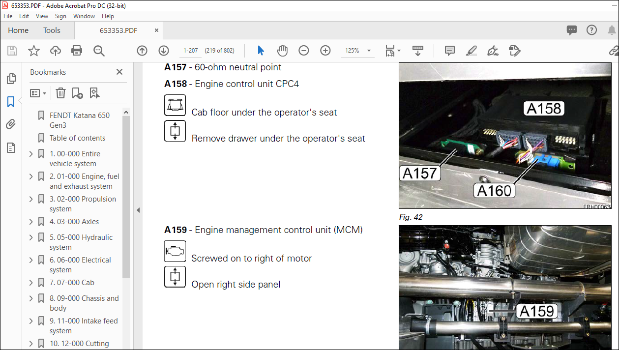
187 Electrical/electronic components – M 1-238
188 Electrical/electronic components — N 1-241
189 Electrical/electronic components – R 1-242
1810 Electrical/electronic components – S 1-242
1811 Electrical/electronic components – U 1-248
1812 Electrical/electronic components – X 1-248
1813 Electrical/electronic components – Y 1-257
1814 Hydraulic components 1-263
1815 Hydraulic measuring points 1-279
1816 Compressed air system components 1-286
2 01-000 Engine, fuel and exhaust system 2-1
21 General 2-3
211 Engine horsepower: comparison of standards and directives 2-3
212 General description of the common rail system 2-5
213 Electrical component designations FENDT – MTU BR1500 2-6
214 General BR1500 2-7
22 Fuel system 2-9
221 Diagnostic options on the fuel system 2-9
23 Oil circuit 2-11
231 Check the engine oil pressure 2-11
24 Valve gear 2-14
241 Adjusting valve clearances 2-14
25 Turbocharger 2-15
251 Assessment of the turbocharger when the engine produces blue smoke 2-15
26 Cooling circuit 2-16
261 Drain coolant 2-16
27 Fan 2-17
271 Fan belt drive taper locking hubs 2-17
3 02-000 Propulsion system 3-1
31 General 3-3
311 Transport and store axial piston units 3-3
312 Cleaning and maintenance 3-5
32 Drive train variable displacement pump 3-6
321 Drive pump device description 3-6
33 Front wheel gear 3-11
331 Removing the wheel transmission 3-11
332 Fit the wheel transmission 3-13
333 Bleeding the parking brake and service brake 3-14
334 Release parking brake manually 3-16
335 Disassemble parking and service brake – Bonfiglioli 3-18
336 Assemble parking and service brake – Bonfiglioli 3-23
337 Disassemble the outer wheel transmission – Bonfiglioli 3-30
338 Assemble the outer planetary transmission – Bonfiglioli 3-33
4 03-000 Axles 4-1
41 Rear axle 4-3
411 Rear axle type DANA 733-146 / 733-147 4-3
5 05-000 Hydraulic system 5-1
51 Working hydraulics 5-3
511 Y140 to Y150 auxiliary spool valves 5-3
512 Rear axle suspension valve disk 5-6
52 High-pressure hydraulics 5-8
521 Fill the high-pressure circuit 5-8
6 06-000 Electrical system 6-1
61 General 6-5
611 Component identification in accordance with DIN 40719 6-5
612 Identification of electrical cables 6-6
613 Terminal designations 6-9
614 Ultrasonic splice vs butt connectors 6-10
615 Relay 6-11
616 Hall sensor operation 6-13
617 Functionality of switch/pushbutton 6-20
618 Rotary position sensor function, when used as a current divider 6-26
619 Pressure sensor function, when used as a current divider 6-31
62 Function descriptions 6-36
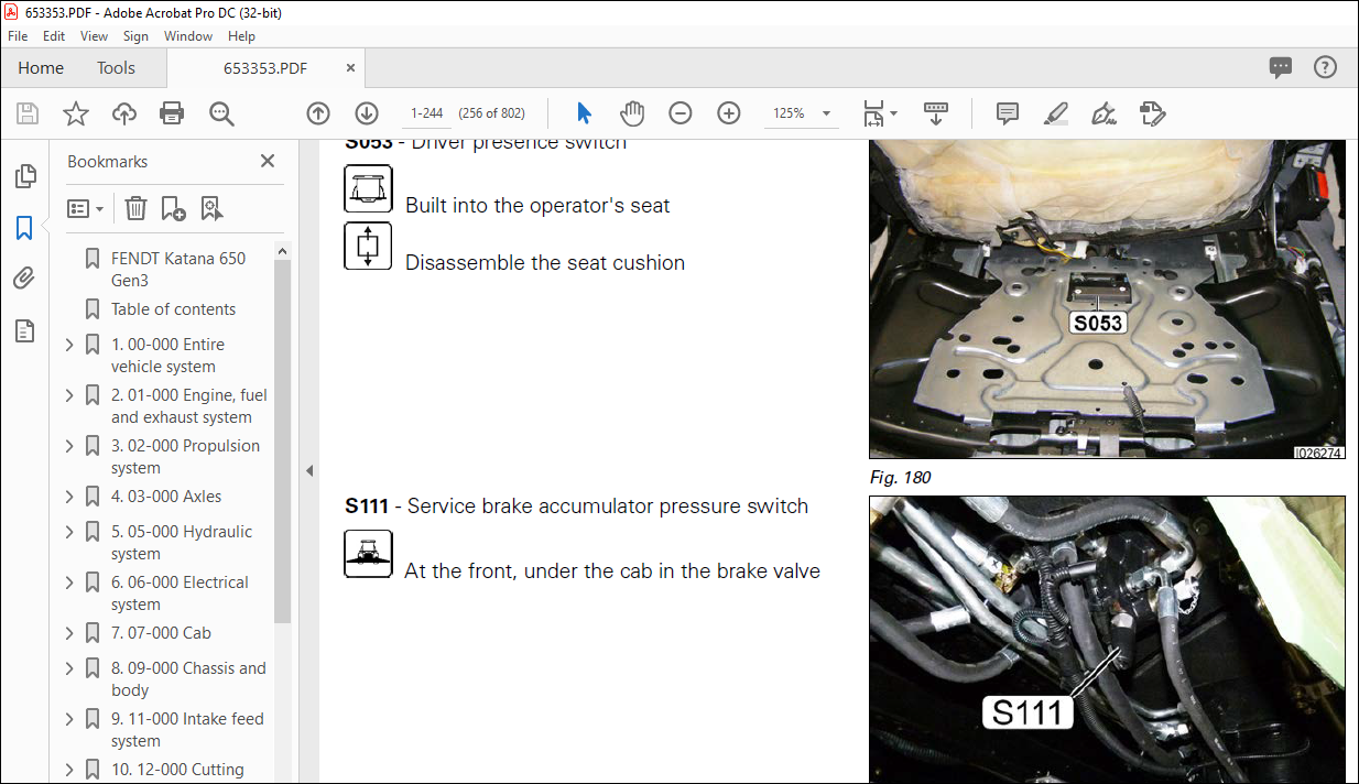
621 Functional description S053 – Driver presence switch 6-36
622 Functional description of stop button on joystick 6-37
623 Functional description S077 – Emergency stop switch 6-38
624 Remove and fit the joystick 6-39
63 Measure and test – A components 6-41
631 Electrical/electronic components – A 6-41
632 A013 – Microfuse board 6-41
633 A050 – Basic control unit (EXT): Check supply voltages 6-46
634 A050 – Basic control unit (EXT): CAN bus connection 6-48
635 A050 – Basic control unit (EXT): Pin assignment 6-50
636 Check A050 – Basic control unit (EXT) with adapter box 6-58
637 A100 – Multifunction armrest (MFA) 6-61
638 Check A100 – Multifunction armrest (MFA) with adapter box 6-66
639 A103 – NT0x terminal Remove 6-68
6310 A126 – Lighting control panel 6-70
63101 A126 – Lighting control panel Remove 6-72
6311 A130 – Central electrical system: Relay overview 6-73
6312 A130 – Central electrical system: Comfort bus 6-75
6313 A130 – Central electrical system: Air conditioning compressor magnetic clutch 6-77
6314 Check A130 – Central electrical system with adapter box 6-78
64 Measure and test – B components 6-81
641 Electrical/electronic components – B 6-81
Table of contents
FENDT Katana 650 Gen3
X990005754011
642 B067 – Steering angle sensor 6-81
643 B076 – Exterior temperature sensor 6-82
644 B081 – Steering wheel sensor (360° rotation angle) 6-84
645 B084 – Hydraulic oil fill level sensor 6-86
646 B108 – Rear axle hydraulic motor sensor (speed/direction of rotation) 6-88
647 B109 – Right wheel motor sensor (speed/direction of rotation) 6-90
648 B110 – Left wheel motor sensor (speed/direction of rotation) 6-92
649 B112 – Forward traction drive high-pressure sensor 6-94
6410 B113 – Reverse traction drive high-pressure sensor 6-96
6411 B114 – Feed sensor (speed/direction of rotation) 6-98
6412 B115 – Header sensor (speed/direction of rotation) 6-100
6413 B116 – Main transmission lubrication pressure sensor 6-102
6414 B117 – Metal detector 6-104
6415 B120 – Cutting unit speed sensor 6-106
6416 B121 – Suspension position sensor 6-107
6417 B131 – Header position rotary position sensor 6-109
6418 B132 – Header tilt rotary position sensor 6-110
6419 B134 – Wheel motor discharge temperature sensor 6-112
6420 B136 – Hydraulic oil temperature sensor 6-114
6421 B146 – Main transmission speed sensor 6-116
6422 B154 – Spout rotation rotary position sensor 6-118
6423 B155 – Spout height rotary position sensor 6-119
6424 B156 – Spout flap rotary position sensor 6-121
6425 B175 – Central lubrication fill level sensor 6-122
6426 B181 – Left press roll deflection 6-124
6427 B182 – Right press roll deflection 6-125
6428 B186 – Main transmission temperature sensor 6-127
6429 B190 – Header ground pressure sensor 6-129
6430 B197 – LS pump pressure monitor sensor 6-131
6431 B200 – Central lubrication transmitter 6-133
6432 B207 – Left maize header sensor bracket 6-134
6433 B208 – Right maize header sensor bracket 6-136
6434 B209 – Steering row sensor 6-137
6435 B216 – Fuel supply ultrasound sensor 6-139
65 Measure and test – S components 6-141
651 Electrical/electronic components – S 6-141
652 S026 – Steering pump flow monitor switch 6-141
653 S035 – High-pressure/low-pressure switch (air-conditioning system) 6-142
654 S111 – Service brake accumulator pressure switch 6-143
655 S112 – Long chop length switch 6-145
656 S113 – Short chop length switch 6-147
657 S120 – Reverse header button 6-149
658 S121 – Raise header button 6-150
659 S122 – Lower header button 6-152
6510 S130 – Parking brake monitoring pressure switch 6-153
6511 S135 – Grindstone park position solenoid switch 6-155
6512 S136 – Grindstone turn position solenoid switch 6-157
6513 S137 – Solenoid switch, cover flap for grinding device open 6-159
6514 S138 – Solenoid switch, cover flap for grinding device closed 6-161
6515 S139 – Hydraulics filter monitor pressure switch 6-162
6516 S145 – Ground pressure control monitoring 6-164
6517 S151 – Icing protection switch 6-165
6518 S154/S155 support wheel detection switch 6-167
6519 S158 – Right – shear bar adjustment button 6-169
6520 S159 – Right + shear bar adjustment button 6-171
6521 S160 – Left – shear bar adjustment button 6-173
6522 S161 – Left + shear bar adjustment button 6-175
66 Measure and test – U components 6-177
Table of contents
FENDT Katana 650 Gen3
X990005754011
661 Electrical/electronic components – U 6-177
662 U004 – NovAtel Smart 6 receiver 6-177
67 Measure and test – X components 6-179
671 Electrical/electronic components – X 6-179
672 Overview of sockets 6-179
673 X028 – (Cab) ISO socket 6-182
674 X2569 – Silage additive applicator socket 6-183
68 Measure and test – Y components 6-184
681 Electrical/electronic components – Y 6-184
682 Y013 – Suspension lowering solenoid valve 6-184
683 Y014 – Suspension raising solenoid valve 6-186
684 Y123 – Rear-axle motor solenoid valve 6-188
685 Y124 – Front right wheel motor solenoid valve 6-189
686 Y125 – Front left wheel motor solenoid valve 6-191
687 Y126 – Reverse traction drive pump solenoid valve 6-193
688 Y127 – Forward traction drive pump solenoid valve 6-195
689 Y128 – Neutral traction drive pump solenoid valve 6-196
6810 Y129 – Intake feed drive pump solenoid valve 6-198
6811 Y130 – Reverse feed drive pump solenoid valve 6-200
6812 Y131 – Reverse header drive pump solenoid valve 6-201
6813 Y132 – Header feed drive pump solenoid valve 6-203
6814 Y133 – Linkage accumulator activation solenoid valve 6-205
6815 Y134 – Crossfeed cutting cylinder brake solenoid valve 6-206
6816 Y135 – Cutting cylinder brake solenoid valve 6-208
6817 Y137 – Feed drive quick-stop valve 6-210
6818 Y140–Y144 valve (PVG 20) 6-211
6819 Y145–Y150 valve (PVG 20) 6-214
6820 Y151 – Long chop length solenoid valve 6-216
6821 Y152 – Short chop length solenoid valve 6-218
6822 Y153 – Main belt clutch solenoid valve 6-220
6823 Y154 – Hand brake solenoid valve 6-222
6824 Y193 – Air conditioning compressor magnetic clutch 6-224
6825 Y195 – ECO/Power solenoid valve 6-226
7 07-000 Cab 7-1
71 Rear view mirror 7-3
711 Replace the electric mirror glass 7-3
8 09-000 Chassis and body 8-1
81 Entrance step 8-3
811 Swivel entrance step 8-3
9 11-000 Intake feed system 9-1
91 Feed — general notes 9-3
911 Manually rotate the feeder 9-3
912 Detach intake assembly 9-3
913 Open the intake assembly 9-8
914 Remove/install the pendulum frame 9-10
92 Top roller system 9-13
921 Remove upper roller system 9-13
922 Install upper roller system 9-20
923 Remove/install left-hand roller transmission 9-24
9231 Installation 9-25
924 Axial setting of upper roller system 9-27
925 Set press spring assembly 9-29
926 Turn the strips on the upper feed roller 9-30
93 Lower roller system 9-32
Table of contents
FENDT Katana 650 Gen3
X990005754011
931 Remove the lower front roller (metal detector) 9-32
932 Fit the lower front roller (metal detector) 9-34
933 Fit the central and rear lower feed roller 9-37
934 Replace the central lower feed roller shell 9-39
935 Remove right roller transmission 9-40
936 Adjust the cut-off strip on the smoothing roller 9-42
937 Turn the strips on the lower feed roller 9-43
938 Install/remove the steel skid 9-44
94 Conversion from grass to maize 9-46
941 Conversion from grass to maize 9-46
942 Install/remove the steel skid 9-49
943 Turn the strips on the upper feed roller 9-49
944 Pickup and maize header without sensor skids: Release the pendulum frame l 9-50
10 12-000 Cutting system 10-1
101 Grinding device 10-3
1011 Adjust the grinding device cover flap 10-3
1012 Position the grinding carriage 10-3
1013 Adjust grindstone for new blades 10-4
10131 Adjust spring latch 10-7
1014 Readjust grindstone 10-9
10141 Adjust spring latch 10-13
1015 Set the magnetic switch 10-15
102 Shear bar adjustment 10-16
1021 Manually move the shear bar to the maintenance position 10-16
1022 Mechanically adjust the shear bar 10-18
1023 Change the shear bar 10-20
1024 Remove the shear bar adjustment lever 10-23
1025 Install the shear bar adjustment lever 10-25
103 Cutting cylinder 10-28
1031 Install knives 10-28
1032 Remove knives 10-30
1033 Install cover plates 10-33
1034 Replace knives 10-34
1035 Remove cutting unit 10-37
1036 Remove the cylinder concave and frame 10-41
1037 Install the cylinder concave wear plate and frame 10-43
1038 Disassemble the cutting cylinder 10-45
1039 Assemble the cutting cylinder 10-50
11 13-000 Discharge system 11-1
111 Transition housing 11-3
1111 Install the blower 11-3
1112 Set the transition housing 11-6
112 Grain cracker 11-12
1121 Remove/install the grain cracker 11-12
1122 Change the speed difference between the cracker rollers 11-15
1123 Replace cracker roller bearing 11-17
1124 Basic setting for roller spacing of the cracker 11-19
113 Tower turning device 11-23
1131 Swivel mechanism spout extension 11-23
1132 Fitting B154 – Spout rotation rotary position sensor 11-25
1133 Fitting B155 – Spout height rotary position sensor 11-29
1134 Removal of spout 11-30
114 Discharge accelerator 11-32
1141 Remove the rotor 11-32
1142 Install the rotor 11-37
1143 Mount the thrower plates 11-44
1144 Adjust strippers 11-45
1145 Set accelerator clearance 11-47
12 14-000 Harvesting transmission 12-1
121 Main belt drive 12-3
1211 Change main clutch linings 12-3
1212 Fit main drive belt locking hubs 12-5
13 15-000 Central lubrication 13-1
131 General 13-3
1311 Central lubrication 13-3
1312 EP-1 electric pump 13-7
1313 Progressive distributor SXE-2 / MX-F 13-9
1314 Assembly instructions for high pressure hoses 13-13
1315 Repair instructions during a blockage 13-14
14 20-000 Service 14-1
141 Special tools 14-3
1411 Special tools 14-3
1412 Diesel diagnostic kit 14-3
1413 SCR diagnostic kit 14-4
IMAGES PREVIEW OF THE MANUAL:
VIDEO PREVIEW OF THE MANUAL:
PLEASE NOTE:
- This is the SAME manual used by the dealers to troubleshoot any faults in your vehicle. This can be yours in 2 minutes after the payment is made.
- Contact us at [email protected] should you have any queries before your purchase or that you need any other service / repair / parts operators manual.
s.m


