

Fendt Katana 65 Operator’s Manual – PDF DOWNLOAD
IMAGES PREVIEW OF THE MANUAL:

DESCRIPTION:
Fendt Katana 65 Operator’s Manual – PDF DOWNLOAD
1.1 Introduction
1.1.1 Safety instructions: Introduction
Operator’s Manual
NOTE:
- This Operator’s Manual is published and distributed across various markets. The availability of the components referred to – whether as part of the standard equipment or as an accessory – can vary depending on the country or region concerned.
- If you would like to know what equipment features are available in your region, you should contact your FENDT dealer. Under normal conditions, this Operator’s Manual should enable the owner and operator to operate the forage harvester safely.
- If these instructions are followed, the forage harvester, like all FENDT products, will provide faithful service for many years. The FENDT dealer’s commissioning at the operator’s site ensures that you understand both the operating and service instructions.
- You should contact your FENDT dealer if you do not understand any parts of this Operator’s Manual. It is essential that these instructions are understood and observed.
- The instructions do not contain all of the safety and operating instructions for the attachments and accessories that can be fitted at the time of delivery and after delivery of the forage harvester.
- It is imperative that the operator understands and uses the Operator’s Manual relative to these attachments and the accessories.
IMPORTANT:
- This manual must always be kept in the forage harvester. You can obtain a copy of this Operator’s Manual from your FENDT dealer. This chapter of the Operator’s Manual contains a description of specific safety-related standard situations that can arise when operating the forage harvester and during normal maintenance.
- You are also given all of the information required on the correct behavior to adopt in these situations. This chapter is supplementary to the safety instructions contained in other chapters of this Operator’s Manual. Depending on the attachments used and the working conditions on-site or in the maintenance area, additional precautionary measures may need to be taken.
- FENDT has no direct influence on the commissioning, operation, inspection, lubrication or maintenance of the forage harvester. YOU are therefore responsible for the adoption of appropriate safety measures in the areas concerned
TABLE OF CONTENTS:
Fendt Katana 65 Operator’s Manual – PDF DOWNLOAD
1 SAFETY INSTRUCTIONS 17
11 Introduction 19
111 Safety instructions: Introduction 19
12 Intended use 21
121 Intended use 21
13 Safety – symbols and terms used 22
131 Safety – symbols and terms used 22
14 Safety decals and safety instructions 23
141 Check and replace the safety labels and notices 23
142 Explanation and position of the safety decals and safety notes 23
15 General safety instructions 34
151 Reminder about safety notes and safety symbols 34
152 Operator familiarity with the forage harvester functions 34
153 Cab: Entry and exit 35
154 Passenger transport 35
155 Carrying children 35
156 Fill fuel and DEF tanks 35
157 Obligatory steps to be taken before leaving the forage harvester 36
16 Special safety instructions before operating the forage harvester 37
161 Fire prevention 37
162 Protective clothing 37
163 Safety equipment and components 37
164 Forage harvester checks 38
17 Special safety instructions for starting the forage harvester 40
171 Protection of other people 40
172 Safe start 40
173 Checks after starting 40
18 Special safety instructions for using the forage harvester 42
181 General instructions 42
182 Prevent from tipping over 42
183 Driving on public roads 43
184 Implements 44
185 Drive shafts 44
186 Hydraulic system 44
187 Battery 45
188 Cooling system 45
189 Tires 46
1810 Work in the vicinity of high-voltage power lines 46
1811 Fire protection measures 46
19 Special safety instructions for forage harvester maintenance 47
191 Notes on disposal in conjunction with forage harvester maintenance 47
192 General maintenance instructions 47
193 Special instructions for cleaning the forage harvester 47
110 Safety equipment 49
1101 Safety equipment: Use and approval 49
1102 Cab 49
1103 Emergency exit 49
1104 Fire extinguisher 50
2 Cab 51
Table of contents
Operation
650020010016
21 Accessibility 53
211 Entry and exit 53
212 Open the cab door 53
213 Service area entrance step 54
22 Seats 55
221 Fendt Evolution Dynamic 55
222 Safety switch on the operator’s seat 56
223 Passenger seat 57
23 Controls 58
231 Multi-function armrest 58
2311 Set the multi-function armrest 58
2312 Overview 58
2313 Multifunction joystick 59
2314 Multifunction armrest keypad 60
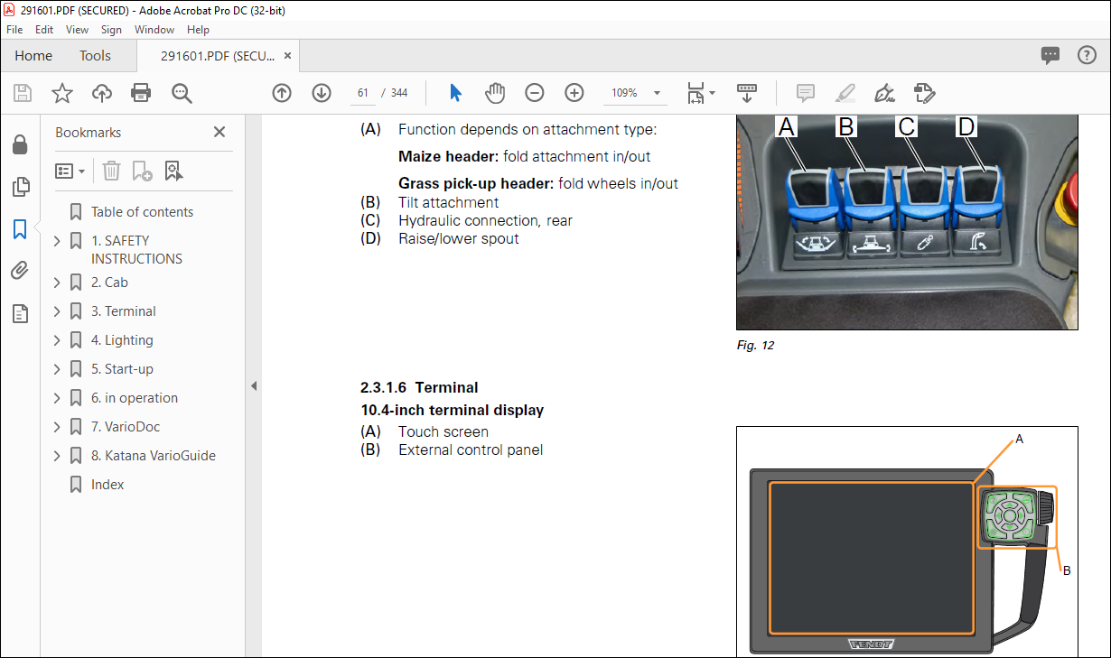
2315 Linear modules 61
2316 Terminal 61
232 Steering column 62
2321 Adjusting the steering wheel and steering column 62
2322 Combination switch 63
2323 Direction indicators from joystick in road mode 63
2324 Preheat and starter switch 63
2325 Indicator lamps in the steering column 63
233 Brakes 64
2331 Service brake 64
2332 Parking brake 64
24 Control panel for headlights and windscreen wiper 65
241 Overview and control 65
25 Main electrical isolation switch 67
251 Switching off main power circuit 67
2511 Switching off main power circuit 67
252 Switching on main power circuit 67
26 Air-conditioning system 69
261 General 69
262 Overview and control 69
263 Air nozzles in the cab 71
264 Filter cleaning 72
27 Camera 73
271 Camera monitoring (optional) 73
28 Mirror 74
281 Adjust the exterior rear view mirrors 74
29 Cleaning 75
291 General 75
292 Cleaning the cab windows and the exterior mirrors 75
210 Other cab elements 76
2101 Sunblind 76
2102 Cool box (optional) 76
2103 Fuses and sockets in the cab 76
211 External control elements 78
2111 External switches at the front – on the left of the entrance platform step 78
2112 External service area switch 78
2113 Switch for the entrance step and maintenance area lighting 79
2114 Sockets 79
3 Terminal 81
31 Terminal quick start guide 83
311 Control panel menu overview 83
Table of contents
Operation
650020010016
312 Maintenance and calibration menu overview 84
313 Diagnostics menu overview 86
314 Menu overview of management 88
315 VarioDoc menu overview 89
316 Map view menu overview 90
317 Info+ screens on Katana terminal 90
318 Instrument panel function 92
319 Calibrate the terminal touch screen 94
3191 Performing calibration 95
3110 Clean the terminal 95
31101 Perform cleaning 96
31102 The following types of cleaning materials are recommended: 97
3111 Terminal day/night mode 97
31111 Night mode 98
32 Basic display and navigation 99
321 104-inch terminal display 99
322 External control panel 99
323 Page layout and screen allocation 100
324 Navigation – control by touch 101
325 Navigation — quick jumps 101
326 Navigation — control with external control panel 102
33 Brief description of the terminal pages 104
331 Forage harvester info and main page 104
3311 Forage harvester information — road operation 104
3312 Forage harvester information — field operation 104
332 Header 106
3321 Header 106
3322 Attachment/feed settings — road operation 107
3323 Header/feed settings — field operation 107
333 Valves 110
3331 Linkage 110
3332 Spout valves (AWB) 112
3333 Front valves 114
3334 Rear valves 116
334 Cutting system 118
3341 Silage 118
3342 Central lubrication 119
335 Grinding 121
3351 Manual grinding 121
336 Engine and transmission 123
3361 Engine and transmission 123
3362 Fuel consumption measurement 124
337 User management 126
3371 User management 126
3372 Wiper settings 128
338 Maintenance and calibration 130
3381 Maintenance and calibration 130
3382 Vehicle calibration 132
3383 Multifunction display (MFA) calibration 133
3384 Drive train calibration 134
3385 Spout calibration (AWB) 135
3386 Linkage calibration 136
3387 Calibrate valves 137
3388 Header and feed calibration 138
339 Diagnostics 139
4 Lighting 141
Table of contents
Operation
650020010016
41 Headlights 143
42 Work lights 144
43 Rotary beacons 145
44 Brake lights and tail lamps 146
45 Direction indicators and sidelights 147
46 Additional lighting 148
47 Attach warning signs to overly wide and overly long vehicles 150
5 Start-up 151
51 Connecting attachments 153
511 Connect attachment 153
5111 Align the pendulum frame 153
5112 Deactivate attachment 153
5113 Switch the hydraulics 154
5114 Ball valve positions 154
5115 Drive shaft 154
5116 Mount drive shaft on the forage harvester 154
5117 Mount drive shaft on the header 155
5118 Connection 155
5119 Connect the electrical cable and hydraulic hoses (maize header) 157
51110 Connect the hydraulic hoses (grass pickup) 158
51111 Secure the maize header with bolts 158
51112 Pickup und maize header without sensor skids: Disconnect the
pendulum frame locking system 158
512 Define List Headers 159
5121 Header page menu sequence 159
5122 Add header 159
513 Calibrate linkage 162
5131 Calibrations to be performed 163
5132 Calibrate sensor skids 163
5133 Calibrate end stops 164
5134 Calibrate attachment tilt 165
5135 Calibrate field pressure sensor 166
52 Change from grass – maize 167
521 Fit cracker 167
5211 Cracker swivel release menu navigation 167
522 Fit panel 170
523 Turn the strips on the upper feed roller 171
6 in operation 173
61 Daily checks 177
611 Daily checks overview 177
612 Check engine oil level 178
613 Check fuel system 179
614 Check the coolant level 180
615 Check the hydraulic oil level at the sight glass 181
616 Check oil level in main transmission 181
617 Check central lubrication system 181
618 Check tire pressure and inspect tires for damage 182
619 Check brake 182
6110 Check the lighting 182
6111 Check drive belts 182
62 Start 183
621 Start engine with key 183
6211 Switch on ignition 183
6212 Displays in steering column while ignition is ON 183
Table of contents
Operation
650020010016
6213 Starting the engine 184
6214 Engine does not start immediately: 184
6215 Display on the terminal 184
622 Boost start 184
63 Reduction in power (de-rating) 185
631 Display on the terminal 185
632 Description of the reduction in power (de-rating) 185
633 Reduction in power when DEF fill level is too low 186
634 Reduction in power when DEF quality is low 187
635 Reduction in power in the event of technical faults or manipulation of the SCR
system 188
636 Reduction in power in the event of reoccurring faults 190
637 Emergency bypass of the power reduction 190
6371 Menu navigation 190
6372 Bypass power reduction 191
64 Stopping 192
641 Stopping the engine 192
642 Stop engine with start/stop button 192
643 Stopping and immobilizing the forage harvester 192
65 Operation 193
651 General 193
652 steering 193
653 Activate road mode 194
654 Release parking brake 194
655 Brakes during operation 194
656 Drive off forwards 194
6561 Braking during forward travel 195
6562 Braking to a standstill 195
657 Reversing 196
6571 Braking during reverse travel 196
6572 Braking to a standstill 197
658 Change of travel direction 197
659 Programmed change in direction of travel 197
6591 Set and pre-select the forwards/reversing speed 198
6592 Terminal display 198
6593 Set reversing rate 199
6594 Carry out programmed change in direction of travel 199
6510 Cruise control 199
65101 Menu navigation 200
65102 Set and save cruise control speeds: 200
65103 Set reversing rate 201
65104 Carry out cruise control 201
65105 Terminal display 202
6511 Load limit control 202
65111 Menu navigation 202
65112 Adjust load limit control 203
65113 Set the maximum speed for load limit control 204
65114 Set approach rate for load limit control 205
65115 Activate load limit control 205
65116 Terminal display 206
6512 Traction control (ASR) 206
65121 Switch off ASR 207
65122 Terminal display 207
6513 Emergency stop 208
6514 Joystick stop key 209
66 Road travel 210
661 Transport position 210
Table of contents
Operation
650020010016
662 Activate shock load stabilizing system for the header 211
6621 Activate shock load stabilizing system 211
663 Driving 211
6631 Road operating mode 212
664 Driving in shunting mode 212
6641 Menu navigation 212
6642 Activate shunting mode 213
6643 Shunting mode active 214
665 Direction indicators from joystick in road mode 214
67 Field mode 215
671 Settings prior to field use 215
672 Activate field mode 215
673 Lower/raise the linkage manually 216
6731 Lower the linkage manually 216
6732 Raise the linkage manually 216
674 Set the maximum and minimum lifting height for the header 216
6741 Set the maximum lifting height of attachment 216
675 Lower/raise the linkage automatically 217
6751 Lower the linkage automatically 217
6752 Raise the linkage automatically 217
676 ECO/POWER mode 217
6761 Activate ECO mode 218
6762 POWER mode 218
6763 Activate POWER mode 218
677 Activate automatic shutdown for the header 219
678 Activate header contour control 220
679 Activate position control 221
6710 Activate field pressure control 222
6711 Switch the feed and header on and off 223
67111 Preliminary conditions 223
67112 Engage feed and header 223
67113 Disengage feed and header 223
6712 Reverse feed and header 224
6713 Metal detection 224
6714 Signal at metal detection 224
67141 Select signal 225
6715 Setting the chop length 226
6716 Manually control the spout 226
67161 Rotate spout 227
6717 Automatic spout operation 227
67171 Save the working position 229
67172 Mirror function and automatic flap function 229
6718 Cutting knives — set grinding duration 230
67181 Menu navigation 230
67182 Set grinding duration 231
6719 Cutting knives — manual sharpening 231
67191 Menu navigation 231
67192 Manually initiate grinding 232
6720 Adjusting the shear bar manually 234
67201 Menu navigation 235
67202 Release external buttons 235
67203 Adjust the shear bar 236
6721 Define freely assignable buttons 236
67211 User Management menu sequence 237
67212 Select the assignment key and assign as an option 238
6722 Create user 239
67221 User Management menu sequence 239
67222 Add user 240
Table of contents
Operation
650020010016
6723 Call up and switch on the throughput measurement 241
67231 Density calculation for the crop 242
6724 Trailer filling display 243
67241 Reset of the trailer filling display via touch 244
67242 Reset of the trailer filling display via a freely assignable button 244
68 Trailer operation 246
69 Towing 247
7 VarioDoc 249
71 System overview 251
711 VarioDoc system overview 251
712 VarioDoc Pro system overview 251
72 VarioDoc menu overview 252
721 VarioDoc info 252
722 VarioDoc main page 253
723 On-board computer 254
724 Data Settings 256
73 VarioDoc operation 258
731 VarioDoc info 258
732 Call up the VarioDoc Main page and select the task 259
733 Add the elements for a task 262
734 Change/delete elements from the task 264
735 Filter the elements 265
736 Call up and switch on the on-board computer 268
737 Start / pause the task 271
738 Enter the task 273
739 Process effective and ineffective time and distance 274
7310 Copy task/Create template 275
7311 Data exchange with office PC 278
7312 Memory space monitoring 281
74 Map view operation 282
741 Map view – full screen 282
742 Map view – zoom 283
743 Set markers 283
744 Marker settings 284
745 Worked areas 284
75 Faults and remedy 287
751 Carry out VarioDoc system test 287
752 VarioDoc system test results 289
8 Katana VarioGuide 291
81 About way-line guidance 293
82 Katana VarioGuide menu overview 297
821 VarioGuide info 297
822 Vario-Guide Main Menu 298
823 VarioGuide steering settings 299
83 Map view 301
831 Map view full screen 301
832 Steering status 301
833 Marker Management 302
834 Set markers 303
835 Worked area settings softkey (D) 304
84 Vario-Guide Main Menu 306
85 Field Settings 307
851 Field settings (main menu) 307
852 Record field boundary 307
Table of contents
Operation
650020010016
853 Add a way-line/select the type of way-line 310
854 Way-line A/B 311
855 Wayline Curve 312
856 Angled way-line 314
857 Obstacle recording/obstacle management softkey (G) 315
86 Steering Settings 319
861 VarioActive superimposed steering 319
87 Signal settings 322
871 Signal settings main menu 322
872 System information and gyro calibration softkey (B) 322
873 Gyro information softkey (C) 325
874 NMEA softkey (D) 326
875 Softkey (G) for selecting GPS or row sensor way-line guidance systems 327
88 Headland settings 329
89 Calibration 330
891 Gyro calibration 330
892 Calibrate steering angle sensor and steering valve 330
810 VarioGuide system components & controls 335
8101 Katana VarioGuide components 335
8102 Switch on VarioGuide 336
811 Automatic way-line guidance switch-off 338
8111 Switch-off limits 338
9 Index 339
Table of contents
VIDEO PREVIEW OF THE MANUAL:
PLEASE NOTE:
- This is the SAME exact manual used by your dealers to fix your vehicle.
- The same can be yours in the next 2-3 mins as you will be directed to the download page immediately after paying for the manual.
- Any queries / doubts regarding your purchase, please feel free to contact [email protected]
S.M


