

DOOSAN SOLAR030 EXCAVATOR PARTS MANUAL S2021 7129FEF – PDF DOWNLOAD
DESCRIPTION:
DOOSAN SOLAR030 EXCAVATOR PARTS MANUAL S2021 7129FEF – PDF DOWNLOAD
- Daewoo reserves the right to improve our products in a continuing process to provide the best possible product to the market place. These improvements can be implemented at any time with no obligation to change materials on previously sold products.
- It is recommended that consumers periodically contact their distributors for recent documentation on purchased equipment. This documentation may include attachments and optional equipment that is not available in your machine’s package.
- Please call your distributor for additional items that you may require. Illustrations used though out this manual are used only a representation of the actual piece of equipment, and may vary from the actual item
2. HOW TO USE THIS PARTS LIST
- Key No. : It shows the reference no. on the illustration. Part No. : It shows the part number. Description : It shows the name of part. Components of an assembly part are shown with marks and are shown on the line, or lines, below the assembly part.
- Also if the components with [.] mark consists of further components part. these further components are shown by the marks [ .. ]. Q’ty : It shows the quantity use for one machine. quantity of components show the quantity for one assembly part. Service code : Abbreviations in this column have their own meaning as show below.
- B: The parts with this abbreviation shows that the part requires some work on it before installing in the machine. D: The part with this abbreviation is a component of an assembly and is not available independently. The assembly part containing this part should be ordered. K: This means that the part is contained in the service part kit.
- M: This means that the part is available only with its mating parts altogether. R: The part with this abbreviation shows that the quantity of the part is changed depending on the machine, such as an adjusting shim etc.
- S: This part is specially provided as a service part, which was not provided in the machine before shipping from the factory. G: This part need grade control and should be requested as the same grade of counter part. OP: Optional parts. EX: Specific design parts.
- OS: Over-sized parts. US: Under-sized parts. (Part with abbreviation “OS” or “US” is described on the line below the standard sized part.) #: The part with this mark is newly added on that page of the equipment.
- Serial no. : Serial No. shows the machine serial number which the parts were applied. As to the engine Serial No. shows only engine serial number which the parts were applied.
- Parts without any applicable serial number are used in every machine. ICA : ICA shows the interchangeability between the original and the improved parts. Abbreviations used in this column are as follows; : Part No.
- in the column of “Replaceable part” can be used instead of this part but not vice versa. P : This must not be used for machine. The part No. in the column “Replaceable part” should be used instead.
- T : Parts Nos. those in the column of “Replaceable part” can be used as an assembly instead of this part. Y : The~ part and the part in the column of “Replaceable part” are interchangeable with each other.
- BLANK : This part has no “Repleace part” Replaceable part: Interchangeable parts nos. and their required quantity are shown in this column. If interchangeable improved parts are provided for the parts which you may order, the improved parts classified as “I”, “P” “T” or “Y” may be supplied. • When repairing, it is recommended to use our standard part.
- Researching the assembling parts from Part No., see the 1Parts Index of this PARTS LIST
TABLE OF CONTENTS:
DOOSAN SOLAR030 EXCAVATOR PARTS MANUAL S2021 7129FEF – PDF DOWNLOAD
41 ENGINE PARTS
Fig. 100 REPAIR KIT PIECES DE RECHANGE 2
101 CYLINDER HEAD CULLASSE 4
102 CYLINDER BLOCK BLOC CYLINDRES 6
103 TIMING GEAR CASE CARTER DE DISTRITION 10
104 FLYWHEEL HOUSING CARTER DE VOLANT MOTEUR 14
105 OIL PAN CARTER D’HUILE 16
106 OIL PUMP POMPE A HUILE 18
107 PISTON & CRANK SHAFT ASS’Y PISTON ET CHAPEAU 20
108 VAL VE MECHANISM VANNE 22
109 FILTER FILTRE 24
110 COOLING SYSTEM SYSTEME DE REFROIDSSEMENT 26
l l l INTAKE & EXHAUST SYSTEM TUBULURE ET COLLECTEUR 28
112 AIR CLEANER FILTRE A AIR 30
113 FUEL SYSTEM SYSTEME DE GAZOLE 32
114 ENGINE FOOT MOTEUR DE MONTAGE 34
115 INJECTION PUMP,CAM SHAFT,IDLE GEAR POMPE D’INJECTION,CHAPEAU,PIGNON 36
116 ELECTRIC PARTS EQUIPMENT ELECTRIQUE 38
117 SURGE TANK RESERVOIR 40
118 MUFFLER SILENCIEUX 42
119 INJECTION PUMP POMPE D’INJECTION 44
120 NOZZLE ASS’Y ENSEMBLE DE INJECTEUR 48
121 STARTER DEMARREUR 50
122 GENERATOR ALTERNATEUR 52
123 AIR CLEANER FILTRE A AIR 54
41 BODY PARTS
56
Fig. 1110 FLOOR PLATE PLAQUE 65-1
111 l SEAT PLATE SI EGE LE SUPPORT 65-3
1113 FLOOR PLATE TOLE DE PLANCHER 65-5
1115 SEAT ASST SIEGE 66
1120 CONTROL SYSTEM( l) SYSTEME DE CONSOLE 69-1
1121 CONTROL SYSTEM( 1-l) SYSTEME DE CONSOLE 70
1130 CONTROL SYSTEM(2) SYSTEME DE CONSOLE 73-1
1131 CONTROL SYSTEM(2- l) SYSTEME DE CONSOLE 74
1140 CONTROL SYSTEM(3) SYSTEME DE CONSOLE 80
1150 CONTROL SYSTEM(4) SYSTEME DE CONSOLE 84
1160 CONTROL SYSTEM(5) SYSTEME DE CONSOLE 88
1170 FUEL TANK RESERVOIR /A GAZOLE 92
1171 OIL TANK RESERVOIR DE HUILE 94
1180 ENGINE COVER COVERCLE 99-11190 CANOPY COVERCLE 100
1200 TRACK(l) TRAIN DE ROULEMENT 102
1210 TRACK(2) TRAIN DE ROULEMENT 106
1220 POWER UNIT(l) MOTEUR 108
1230 POWER UNIT(2) MOTEUR 112
1240 POWER UNIT(3) MOTEUR 116
1250 POWER UNIT(4) MOTEUR 118
1260 HYDRAULIC PIPING(l) CIRCUIT REFROIDSSEMENT 120
1270 FRONT PIPING CONDUITES FRONT ALES 124
1280 HYDRAULIC PIPING(2) CIRCUIT REFROIDSSEMENT 128
1290 HYDRAULIC PIPING(3) CIRCUIT REFROIDSSEMENT 134
1300 HYDRAULIC PIPING(4) CONDUITES CIRCUIT PILOTE 138
1310 HYDRAULIC PIPING(5) CONDUITES CIRCUIT PILOTE 140
1315 HYDRAULIC PIPING(5-l) FOR U.S.A CONDUITES CIRCUIT PILOTE 142
1320 TRAVELING PIPING CONDUITES DE TRASLATION 144
1330 ELECTRIC SYSTEM( l) EQUIPMENT ELECTRIQUE 146
1331 ELECTRIC SYSTEM( l -l) EQUIPMENT ELECTRIQUE 151-1
1335 ELECTRIC SYSTEM(l-1)-CONTROL STAND EQUIPMENT ELECTRIQL!E 151-5
1340 ELECTRIC SYSTEM(2) EQUIPMENT ELECTRIQUE 152
1341 ELECTRIC SYSTEM(2- l) EQUIPMENT ELECTRIQUE 155-1
1350 CABIN CABINE 156
1360 ACCUMULATOR-OPTION RESERVOIR 158
1370 FLOOR PLATE PLAQUE 160
1371 SEAT PLATE SIEGE LE SUPPORT 165-1
1373 CONTROL STAND(l)-L.H CONSOLE DE COMMANDE 165-3
1375 CONTROL STAND(2)-R.H CONSOLE DE COMMANDE 165-7
1380 FRONT(l) FRONT ALES 166
1381 FRONT( l )-BOOM FRONT ALES 170
1390 FRONT(2) FRONT ALES 174
1391 FRONT(2)-ARM FRONT ALES 178
1400 NAME PLATE-KOREAN ~~~~ ~ 182
1410 NAME PLATE-ENGLISH PLAQUE D’IDENTIFICATION 184
1420 NAME PLATE-JAPAN PLAQUE D’IDENTIFICATION 188
1425 NAME PLATE-EUROPE PLAQUE D’IDENTIFICATION 191-1
1430 TOOLS OUTILLAGE 192
1440 SPARE PARTS PIECES DE RECHANGE 194
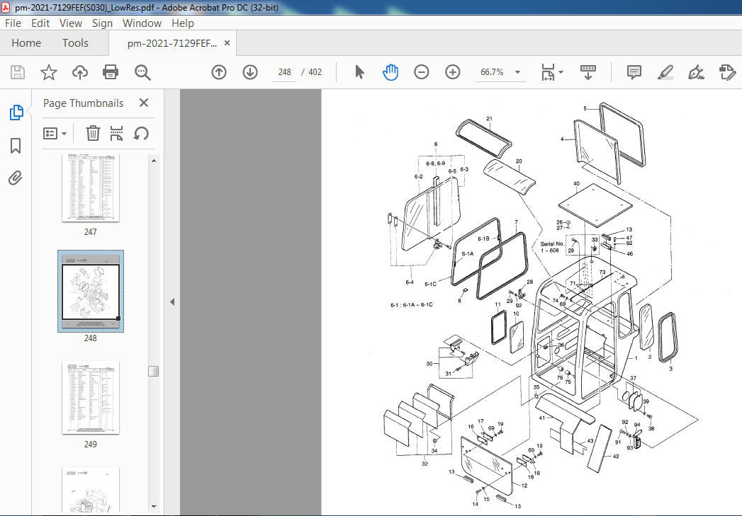
1450 CABIN(l) CABINE 196
1460 CABIN(2) CABINE 202
1470 CABIN(3) CABINE 206
1480 CABIN(4) CABINE 214
1490 SEAT-EXPORT SIEGE 218
1491 SEAT-EXPORT SIEGE 219-1
1495 SEAT-OPTION SIEGE 219-3
1500 BREAKER PIPING-ONE WAY CONDUITES FRONT ALES 220
1505 BREAKER PIPING-TWO WAY CONDUITES FRONTALES 222
1507 CONTROL L~i~~A~ SVSTEME DE CONSOLE 223-1
1510 FRONT-BRE~~ A S BOOK IS FOR RE~~~&§ ONLY. 224
NUMBERS AND SERAIL NUMBERS MAY BE
S030 OUTDATED. ALWAYS USE THE ONLINE PARTS SYSTEM)
1520 CABIN-FGPS CABINE
1530 CABIN( 1 )-OPTION CABINE
1540 CABIN(2)-OPTION CABINE
1550 CABIN(3)-OPTION CABINE
1560 CABIN(4)-OPTION CABINE
1570 CABIN SPONGE EPONGE
1580 CANOPY COUVERCLE
1590 CONTROL SYSTEM-OPTION SYSTEME DE CONSOLE
e HYDRAULIC COMPONENTS
Fig. 2100 CONTROL VALVE(l) VANNE DE COMMANDE
2110 CONTROL VAL VE(2) VANNE DE COMMANDE
2111 CONTROL VALVE VANNE DE COMMANDE
2115 CONTROL VALVE·FOR EUROPE VANNE DE COMMANDE
2120 CENTER JOINT JOINT TOURNANT
2130 MAIN PUMP POMPE
2140 TRAVEL MOTOR SYSTEME DE TRANSLATION
2142 REDUCTION GEAR REDUCTEUR D’ORIENT ATION
2150 SWING MOTOR MOTEUR D’ORIENTATION
2160 SOLENOID VALVE VANNE DE COMMANDE
2161 SOLENOID VALVE VANNE DE COMMANDE
2162 SOLENOID VALVE VANNE DE COMMANDE
2170 JOYSTICK VALVE ASS’Y COMMAND DE DISTANCE
2171 JOYSTICK VAL VE ASS’Y COMMAND DE DISTANCE
2180 BOOM CYLINDER VERIN DE FLECHE
2181 BOOM CYLINDER VERIN DE FLECHE
2190 ARM CYLINDER VERIN DE BALANCIER
2191 ARM CYLINDER VERIN DE BALANCIER
2200 BUCKET CYLINDER VERIN DE GODET
2201 BUCKET CYLINDER VERIN DE GODET
2210 SWING CYLINDER VERIN DE ORIENTATION
2211 SWING CYLINDER VERIN DE ORIENTATION
2220 DOZER CYLINDER VERIN DE DOZER GAUCHE
2221 DOZER CYLINDER VERIN DE DOZER GAUCHE
VIDEO PREVIEW OF THE MANUAL:

IMAGES PREVIEW OF THE MANUAL:


PLEASE NOTE:
- This is the SAME manual used by the dealers to troubleshoot any faults in your vehicle. This can be yours in 2 minutes after the payment is made.
- Contact us at [email protected] should you have any queries before your purchase or that you need any other service / repair / parts operators manual.
S.M


