

")
CAT Siemens SIMOREG DC Master 6RA70 Series Base Drive Instructions Manual BI619357 – PDF DOWNLOAD
FILE DETAILS:
CAT Siemens SIMOREG DC Master 6RA70 Series Base Drive Instructions Manual BI619357 – PDF DOWNLOAD
Language : English
Pages : 165
Downloadable : Yes
File Type : PDF
IMAGES PREVIEW OF THE MANUAL:

DESCRIPTION:
CAT Siemens SIMOREG DC Master 6RA70 Series Base Drive Instructions Manual BI619357 – PDF DOWNLOAD
Description:
2.1 Base Drive Panel Description:
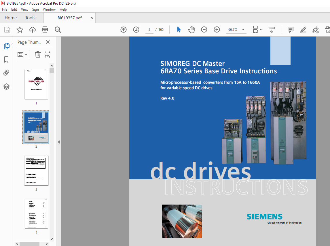
Series 6RA70 SIMOREG DC MASTER Base Drive Panels are complete drive assemblies ready to be
installed and operated. They include a 3-phase armature converter, single-phase field converter, main
contactor, protective semiconductor fuses, control power transformer, and power / control terminals.
Base Drive Panels are fully digital, compact units which supply the armature and field of variablespeed
DC drives with rated armature currents from 15A to 1660A. The motor field circuit can be
supplied with DC currents of up to 40A (current levels depend on the armature rated current).
2.2 General Information:
Series 6RA70 SIMOREG DC MASTER converters are characterized by their compact, space-saving
construction. Their compact design makes them particularly easy to service and maintain since
individual components are readily accessible. The electronics box contains the basic electronic
circuitry as well as any supplementary option boards.
All SIMOREG DC MASTER units are equipped with a PMU simple operator panel mounted in the
converter door. The panel consists of a five-digit, seven-segment display, three LED’s as status
indicators and three parameterization keys. The PMU also features connector X300 with an USS
interface in accordance with the RS232 or RS485 standard. The panel provides all the facilities for
making adjustments or settings and displaying measured values required to start-up the converter.
The OP1S optional converter operator panel can be mounted directly in the converter door or
externally, e.g., in the cubicle door. When mounted remotely, the OP1S can be connected to the
converter with cables up to 5 meters (15 feet) length. Cable up to 200 meter (600 feet) in length can be
used if a separate 5 VDC power supply is available. The OP1S connects to the SIMOREG through
connector X300 using the RS485 interface. The OP1S can be installed as an economic alternative to
conventional door mounted metering devices (i.e., voltmeters, ammeters, and speed indicator).
The OP1S features a liquid crystal display with 4 x 16 characters for displaying parameter names in
plain text. English, German, French, Spanish and Italian can be selected as the display languages. In
addition the OP1S can store parameter sets for easy downloading to other drives.
The converter can also be parameterized on a standard PC with appropriate software connected to the
serial interface on the basic unit. This PC interface is used during start-up, for maintenance during
shutdown and for diagnosis in operation. Furthermore, converter software upgrades can be loaded
through this interface for storage in flash memory.
On single-quadrant converters, a fully controlled three-phase bridge supplies the armature. On fourquadrant
converters, two fully controlled three-phase bridges are connected in an inverse-parallel
connection to allow both positive and negative armature current. For the field converter, a singlephase,
half-controlled 2-pulse bridge supplies the motor shunt field.
The armature and field converters can operate with AC line frequencies from 45 to 65 Hz. If required
for a specific application, the frequency of the armature and field AC supplies can be different. The
armature converter 3 phase AC supply is phase insensitive however on base drives rated 1180 and
1660 amperes, the 3 phase cooling fan must be connected to get the proper direction of rotation. The
power section cooling system is monitored by means of temperature sensors.
TABLE OF CONTENTS:
CAT Siemens SIMOREG DC Master 6RA70 Series Base Drive Instructions Manual BI619357 – PDF DOWNLOAD
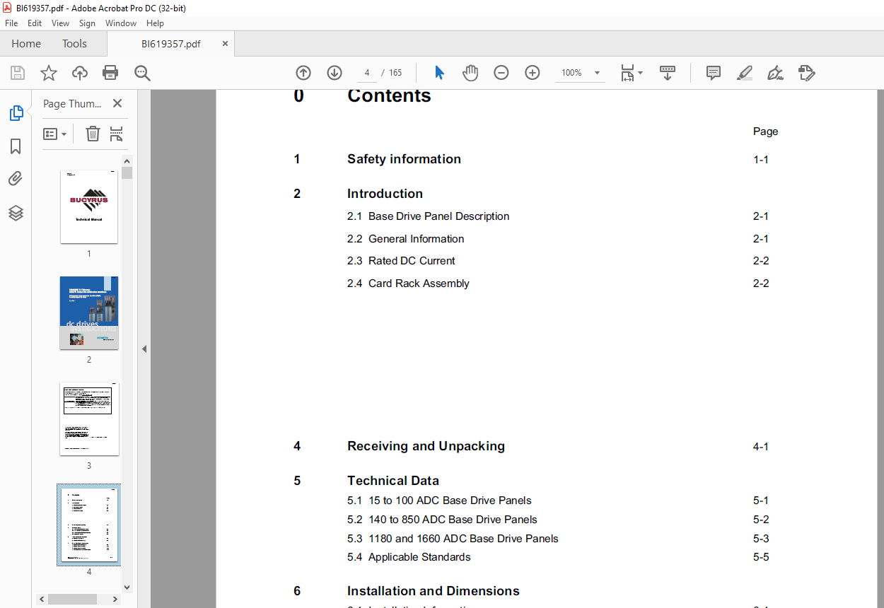
1 Safety information
2 Introduction
2.1 Base Drive Panel Description
2.2 General Information
2.3 Rated DC Current
2.4 Card Rack Assembly
4 Receiving and Unpacking
5 Technical Data
5.1 15 to 100 ADC Base Drive Panels
5.2 140 to 850 ADC Base Drive Panels
5.3 1180 and 1660 ADC Base Drive Panels
5.4 Applicable Standards
6 Installation and Dimensions
6.1 Installation Information
6.2 Base Drive Panel Outlines
7 Base Drive Panel Connections
7.1 Base Drive Panel Schematics
7.2 Control Connections CUD1
7.3 Control Connections CUD2
7.4 Description of Power/Control Terminals
8 Start-up
8.1 General safety information
8.2 Operator control panels 8.3 Parameterization procedure 8.4 Typical connection diagrams
8.5 Reset to factory default values 8.6 Start-up procedure
9 Faults and Alarms
9.1 Fault messages
9.2 Alarm messages
10 Abbreviated Parameter List
10.1 Overview
10.2 Overview of Abbreviations
10.3 Operating Status Display
10.4 General Visualization Parameters
10.5 Access Authorization Levels
10.6 Definition of SIMOREG Converter
10.7 Setting Values for Converter Control
10.8 Definition of Motor
10.9 Definition of Speed Sensing Pulse Encoder
10.10 Armature Current Control, Reversing, Gating
10.11 Current/Torque Limitation
10.12 Speed Controller
10.13 Field Current Control, Gating
10.14 Closed Loop EMF Control
10.15 Ramp Function Generator
10.16 Setpoint Processing
10.17 Monitoring Functions and Limits
10.18 Limit-Value Monitors
10.19 Digital Setpoint Inputs
10.20 Torque Shell Input
10.21 Input Quantities for Signals
10.22 Configuring of Closed-Loop Control
10.23 Control and Status Word
10.24 Further Configuring Measures
10.25 Analog Inputs 10-35
10.26 Analog Outputs 10-36
10.27 Binary Outputs 10-36
10.28 Configuration of Serial Interfaces 10-36
10.29 Deactivation of Monitoring Functions 10-41
10.30 Thyristor Diagnostics 10-41
10.31 Parameters for DriveMonitor and OP1S 10-42
10.32 Profile Parameters 10-42
10.33 Resetting and Storing Parameters 10-43
11 Simplified Block Diagrams
VIDEO PREVIEW OF THE MANUAL:
S.V


