

CAT Bucyrus Shield support 2100/4500-2/2×7156/1789 Operating Manual – PDF DOWNLOAD
FILE DETAILS:
CAT Bucyrus Shield support 2100/4500-2/2×7156/1789 Operating Manual – PDF DOWNLOAD
Language : English
Pages :190
Downloadable : Yes
File Type : PDF
IMAGES PREVIEW OF THE MANUAL:

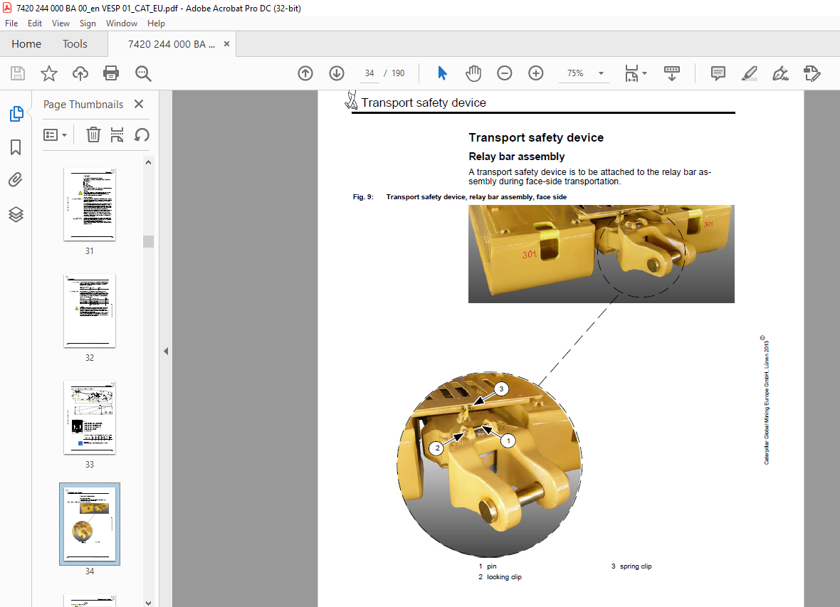
TABLE OF CONTENTS:
CAT Bucyrus Shield support 2100/4500-2/2×7156/1789 Operating Manual – PDF DOWNLOAD
1 About this manual
Before starting work 1 3
Persons for whom the operating manual is intended 1 3
Purpose of this operating manual 1 4
Signs and symbols used 1 4
2 Your safety
Personnel 2 3
Operation 2 3
Installation and repairs 2 4
Operating conditions 2 5
Intended use 2 5
Unauthorized use 2 5
Safety instructions 2 6
3 Storage and transport
Storage 3 3
Storing the equipment 3 3
Storing used equipment 3 4
Transport 3 5
Load units, dimensions and weights 3 5
Before transport 3 5
Transport safety device 3 8
Relay bar assembly 3 8
Flipper 3 9
Staple clip 3 10
Side seal 3 11
4 Installation
Preassembly of the shield units 4 3
Installation of the shield units 4 3
Pressure equalization of the electronic control system 4 5
Supply connections for auxiliary supply 4 6
Establishing a connection between the shields 4 9
Requirements for the face hydraulic system 4 10
Water spraying system requirements 4 11
Commissioning 4 12
To be observed prior to commissioning 4 12
How to put the support into operation 4 14
Anticorrosion protection of hydraulic components 4 14
5 Operation
Requirements 5 3
Operating conditions 5 3
Safety requirements 5 6
Operation of the shield support 5 9
Work safety 5 15
Shield components 5 16
Main components 5 16
Overview of shield hydraulics 5 18
HP ball valve versions 5 18
Functions of the HP ball valves 5 20
Operation of the shield hydraulics 5 21
Arrangement of the hydraulic components 5 21
Shield hydraulics 5 23
Control units 5 42
Intershield manifold 5 43
Emulsion filters 5 44
Manifold 5 45
PMC®-R control unit 5 45
Electrohydraulic control units 5 46
Water valves 5 46
Flipper 5 47
Flipper cylinder 5 48
Leg 5 49
Plug with pressure relief 5 52
Measuring coupling for pressure relief 5 53
Repair and emergency operation 5 54
Operation and functions of the electrohydraulic
control unit 5 56
Shield functions 5 57
Operation of the double backflush filter 5 61
Maintenance 5 62
Special measures 5 62
Daily maintenance 5 63
Weekly maintenance 5 64
Every six months 5 64
Regularly scheduled damage assessment 5 64
Troubleshooting 5 65
Instructions for troubleshooting 5 65
Fault localization 5 65
3/2-way or pilot valve 5 68
Piloted check valves 5 68
Internal bypass inside the leg 5 69
Pressure relief valve defective 5 69
Defective or clogged filter 5 69
Caterpillar Global Mining Europe GmbH, Lünen 2013E
Table of content
Doc No : 7420 244 000 BA 00 VESP / 01
6 Technical data
Description 6 3
Main subassemblies 6 5
Main dimensions 6 7
Base with lemniscatic links and relay bar assembly 6 8
Lemniscatic link 6 12
Canopy 6 14
Flipper 6 16
Leg retainers 6 18
Side seal 6 19
Caving shield 6 24
Caving flap 6 26
Accessories 6 27
Antitopple device “canopy/canopy” 6 27
Brackets 6 35
Covers 6 37
Information signs 6 38
Technical data, steel structure 6 39
Hydraulic system 6 40
Shield hydraulics 6 40
Hydraulic leg, two-stage 6 43
Hydraulic cylinder 6 46
Setup 6 46
Shifting ram (Z2) 6 48
Stabilizing cylinder (Z3) 6 48
Side seal cylinder (Z4) 6 49
Flipper cylinder (Z7) 6 49
Base lifting cylinder (Z9) 6 50
Technical data, hydraulic cylinders 6 51
Pressure relief valves 6 53
Angles of inclination of the canopy 6 55
Hydraulic fluids 6 56
Permissible hydraulic fluids 6 56
Maintenance of the hydraulic fluid 6 58
Quality of the process water 6 58
Greases and lubricating pastes 6 60
Tightening torques 6 62
Screws and bolts with ISO metric thread 6 62
7 For your information
Standards and directives 7 3
Applied standards and directives 7 3
Identification of the shield 7 5
Name plate 7 5
Shield number 7 6
VIDEO PREVIEW OF THE MANUAL:
S.M


