
Case 521e Tier-3 Wheel Loader Service Repair Workshop Manual
FILE DETAILS:
Case 521e Tier-3 Wheel Loader Service Repair Workshop Manual
LANGUAGE:ENGLISH
PAGES:846
DOWNLOADABLE:YES
FILE TYPE:PDF
VIDEO PREVIEW OF THE MANUAL:

IMAGES PREVIEW OF THE MANUAL:


SAMPLE PAGE FROM THE MANUAL:
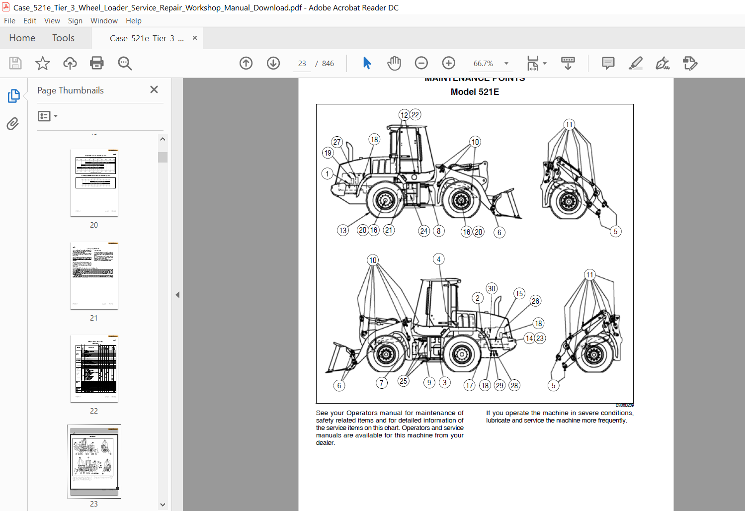
Case 521e Tier-3 Wheel Loader Service Repair Workshop Manual
1. Remove all dirt and grease from the area of the center pivot. Park the machine on a level surface.
2. Lower the bucket until the bucket is flat on the floor.
3. Stop the engine and apply the parking brake.
4. Remove the covers from both sides of the machine.
5. Disconnect the front wiring harness from the cab floor.
6. Remove any tie straps that fasten the front wiring harness to the chassis near the center pivot.
7. Loosen and remove the nut and washer that fasten the chassis ground wire and cab ground wire to the studs.
8. Loosen and remove the bolt, lock washer, and nut that fasten the clamp on the front wiring harness to the bracket on the rear frame. Move the front wiring harness out of the way.
9. Loosen and remove the fill cap for the hydraulic reservoir.
10. Connect a vacuum pump to the hydraulic reservoir. Start the vacuum pump.
TABLE OF CONTENTS:
Case 521e Tier-3 Wheel Loader Service Repair Workshop Manual
General Tab 1
Section Index – General
Standard Torque Specifications 1001
Fluids and Lubricants 1002
Metric Conversion Chart 1003
Engines Tab 2
Section Index – Engines
Engine and Radiator Removal and Installation 2000
Stall Tests 2002
After Cooler 2003
For Engine Repair, See the Engine Service Manual 87630273
Fuel System Tab 3
Section Index – Fuel System
For Fuel System Repair, See the Engine Service Manual 87630273
Electrical Tab 4
Section Index – Electrical
Removal and Installation of Starter and Alternator 4001
Electrical Specifications and Troubleshooting 4002
Batteries 4003
Instrument Cluster 4005
Steering Tab 5
Section Index – Steering
Removal and Installation of Steering Components 5001
Steering Specifications, Pressure Checks, and Troubleshooting 5002
Steering Cylinders 5005
Center Pivot 5006
Auxiliary Steering Motor and Pump 5008
Power Train Tab 6
Section Index – Power Train
Removal and Installation of Power Train Components 6001
Transmission Specifications, Pressure Checks, and Troubleshooting 6002
Transmission 6003
Front Axle 6004
Rear Axle 6004
Drive Shafts, Center Bearing, and Universal Joints 6005
Wheels and Tires 6006
Transmission Control Valve 6007
Brakes Tab 7
Section Index – Brakes
Removal and Installation of Brake Components 7001
Hydraulic Brake Troubleshooting 7002
Brake Pump 7003
Brake Accumulators 7004
Parking Brake 7008
Hydraulics Tab 8
Section Index – Hydraulics
How to Read Hydraulic Schematics 8000
Removal and Installation of Hydraulic Components 8001
Hydraulic Specifications, Troubleshooting, and Pressure Checks 8002
Cleaning the Hydraulic System 8003
Loader Control Valve 8005
Cylinders 8006
Coupler Solenoid Locking Valve 8007
Ride Control Accumulator 8013
Ride Control Valve 8014
Mounted Equipment Tab 9
Section Index – Mounted Equipment
Air Conditioning Troubleshooting and System Checks 9002
Air Conditioner System Service 9003
Removal And Installation Of Air Conditioning And Heater Components 9004
Loader 9006
Roll Over Protective Structure (ROPS), Cab Structural Frame (CSF) 9007
Cab Glass Installation 9010
Electrical Schematic Foldouts and Hydraulic Schematic Foldout In Rear Pocket
PLEASE NOTE:
⦁ This is the same manual used by the dealers to diagnose and troubleshoot your vehicle
⦁ You will be directed to the download page as soon as the purchase is completed. The whole payment and downloading process will take anywhere between 2-5 minutes
⦁ Need any other service / repair / parts manual, please feel free to contact [email protected] . We still have 50,000 manuals unlisted


