

Bobcat X325 X328 Excavator Service Manual 6900462 – PDF DOWNLOAD
FILE DETAILS:
Bobcat X325 X328 Excavator Service Manual 6900462 – PDF DOWNLOAD
Language : English
Pages : 472
Downloadable : Yes
File Type : PDF
Size:11.5 MB
DESCRIPTION:
Bobcat X325 X328 Excavator Service Manual 6900462 – PDF DOWNLOAD
FOREWORD
This manual is for the Bobcat hydraulic excavator mechanic. It provides necessary servicing an d
adjustment procedures for the hydraulic excavator and its component parts and systems. Refer to the
Operation & Maintenance Manual for operating instructions, starting procedure, daily checks, etc
A general inspection of the following items must be made after the hydraulic excavator has had service
or repair:
• The Delivery Report is used to assure that complete instructions have been given to the new owner and that the machine
is in safe operating condition.
• The Operation & Maintenance Manual delivered with the excavator gives operating information as well as routin e
maintenance and service procedures. It is a part of the excavator and must stay with the machine when it is sol d.
Replacement Operation & Maintenance Manuals can be ordered from your Bobcat Excavator dealer.
• The excavator has machine signs (decals) which instruct on the safe operation and care. The signs and their locations
are shown in the Operation & Maintenance Manual. Replacement signs are available from your Bobcat Excavator dealer.
Safety Alert Symbol: This Safety Symbol is used for important safety messages. When you see this symbol follow
the safety message to avoid personal injury or death.
• The Bobcat Hydraulic Excavator has a plastic Operator’s Handbook fastened to the operator cab. It’s brief instructions
are convenient to the operator. The handbook is available from your dealer in an English, French, German, Dutch, Italian,
Spanish, Portugese, Finnish, Danish, and Swedish editions.
• The CIMA Safety Manual delivered with the excavator gives information for safe operating and standard signals.
• The Service Manual and Parts Manual are available from your dealer for use by mechanics to do shop–type service and
repair work.
• The Bobcat compact Excavator Operator Training Course is available through your local dealer
TABLE OF CONTENTS:
Bobcat X325 X328 Excavator Service Manual 6900462 – PDF DOWNLOAD
MAINTENANCE SAFETY 3
ALPHABETICAL INDEX 5
CONTENTS 7
FOREWORD 9
SAFETY INSTRUCTIONS 11
SERIAL NUMBER LOCATIONS 13
HYDRAULIC EXCAVATOR SERIAL NUMBER 13
ENGINE SERIAL NUMBER 13
DELIVERY REPORT 13
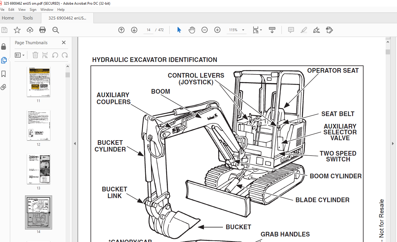
HYDRAULIC EXCAVATOR IDENTIFICATION 14
PREVENTIVE MAINTENANCE 15
SERVICE SCHEDULE 17
LIFTING AND BLOCKING THE EXCAVATOR 18
Procedure 18
TRANSPORTING THE HYDRAULIC EXCAVATOR 19
ENGINE COVER 20
Opening The Engine Cover 20
Adjustment Of The Engine Cover Latch 20
AIR CLEANER SERVICE 21
Replacing The Filter Element (325 S/N 514013001–514014899) 21
Replacing The Filter Element (325 S/N 514014900 &Above) & (328 S/N 516611001 & Above) 23
FUEL SYSTEM 24
Fuel Specifications 24
Filling The Fuel Tank 24
Fuel System Maintenance 25
Fuel Filter (325 S/N 514013001–514014899) 25
Fuel Filter (325 S/N 514014900 & Above) & (328 S/N516611001 & Above) 25
Removing Air From The Fuel System (325 S/N514013001–514014899) 26
ENGINE LUBRICATION SYSTEM 27
Checking Engine Oil 27
Replacement Of Oil And Filter 27
COOLING SYSTEM 28
Coolant Level 28
Coolant Replacement 28
ALTERNATOR BELT 29
Adjustment 29
ELECTRICAL SYSTEM 30
Using A Booster Battery (Jump Starting) 30
HYDRAULIC SYSTEM 31
Checking And Adding Fluid 31
Replacing The Hydraulic Oil 32
Replacing The Hydraulic Filter 32
Replacing The Drain Line Filter 32
SPARK ARRESTOR MUFFLER (325 S/N 514014900 &Above) & (328 S/N 516611001 & Above) 33
Cleaning The Spark Arrestor Muffler 33
SPARK ARRESTOR MUFFLER (325 S/N 514013001–514014899) 34
Cleaning The Spark Arrestor Muffler 34
TRAVEL MOTOR 35
Checking The Oil Level 35
Draining And Refilling 35
LUBRICATION OF THE HYDRAULIC EXCAVATOR 36
HEATER AIR FILTER (With Cab Option Only) (325 S/N514013001–514014899) 39
HEATER AIR FILTER (With Cab Option Only) (325 S/N514014900 & Above) & (328 S/N 516611001 & Above) 39
HYDRAULIC SECTION 41
HYDRAULIC SCHEMATICS 45
HYDRAULIC SYSTEM TROUBLESHOOTING 70
HYDRAULIC SERVICE INFORMATION 75
Description 75
Checking The Main Relief Valves 76
Testing The Swing Circuit Relief Valve 77
Testing The Auxiliary And Bucket Circuit Relief Valve 79
Testing The Left Hand Travel Circuit Relief Valve 81
Testing The Right Hand Travel Circuit Relief Valve 83
Testing The Boom Circuit Relief Valve 85
CROSS PORT RELIEF VALVE 86
Description 86
Testing 86
HYDRAULIC PUMP 87
Checking the Hydraulic Pump 87
Removal And Installation (325 S/N 514013001–514014899) 88
Parts Identification (325 S/N 514013001– 514014899) 89
Removal And Installation (325 S/N 514014900 &Above) & (328 S/N 516611001 & Above) 90
Disassembly (325 S/N 514013001–514014899) 92
Assembly (325 S/N 514013001–514014899) 94
HYDRAULIC CONTROL VALVE (5–Spool) 97
Left Travel, Right Travel, Boom, Bucket and Auxiliary 97
Description 97
Removal And Installation (325 S/N 514013001–514014899) 97
Removal And Installation (325 S/N 514014900 &Above) & (328 S/N 516611001 & Above) 98
Left Travel, Right Travel, Boom, Bucket and Auxiliary 101
Parts Identification 101
Disassembly 102
Outlet Sections Disassembly 103
Mid Inlet Section Disassembly 103
Mid Inlet Section Assembly 103
Left Travel, Right Travel and Auxiliary Disassembly 104
Left Travel, Right Travel and Auxiliary Assembly 106
Boom And Bucket Disassembly 108
Boom And Bucket Assembly 110
Assembly 112
PORT RELIEF VALVES AND MID INLET MAIN RELIEF VALVES 113
Parts Identification 113
Port Relief Valve Pressure Setting 114
Disassembly 114
Assembly 115
MAIN RELIEF VALVES (Adjustable) 116
Parts Identification 116
Pressure Settings 117
Disassembly 118
Assembly 118
Adjusting The Main Relief Valves 119
HYDRAULIC CONTROL VALVE (5–Spool) 120
Boost, Arm, Boom Swing, Blade And Swing Section 120
Description 120
Removal And Installation 120
Parts Identification 121
Disassembly 122
Inlet Section Disassembly 123
Inlet Section Assembly 123
Arm, Boost And Swing Motor Disassembly 124
Arm, Boost And Swing Motor Assembly 126
Boom Swing Disassembly 128
Boom Swing Assembly 130
Blade Disassembly 133
Blade Assembly 135
Assembly 137
ACCUMULATOR 138
Removal And Installation 138
Parts Identification (S/N 514013001 – 514017331& 516611001 – 516611918) 139
Disassembly (S/N 514013001 – 514017331& 516611001 – 516611918) 140
Assembly 142
Parts Identification (S/N 514017312 & Above &516611919 & Above) 145
Disassembly (S/N 514017312 & Above &516611919 & Above) 146
Assembly (S/N 514017312 & Above &516611919 & Above) 148
Testing (All Models) 151
PORT BLOCK 153
Removal And Installation 153
BUILD UP VALVE 154
Description 154
Removal And Installation 154
Disassembly And Assembly 154
AUXILIARY SELECTOR VALVE 155
Removal And Installation (325 S/N 514013001–514014899) 155
Removal And Installation (325 S/N 514014900 &Above) & (328 S/N 516611001 & Above) 155
Disassembly And Assembly 156
OIL COOLER 157
Removal And Installation 157
HYDRAULIC RESERVOIR 158
Removal And Installation 158
HYDRAULIC FILTER ASSEMBLY 160
Removal And Installation 160
CASE DRAIN FILTER 160
BOOM CYLINDER SHIELD 161
Removal And Installation 161
BOOM CYLINDER 161
Removal And Installation 161
BOOM CYLINDER 162
Parts Identification 162
ARM CYLINDER 163
Removal And Installation 163
Parts Identification 164
BUCKET CYLINDER 165
Removal And Installation 165
Parts Identification 166
BLADE CYLINDER 167
Removal And Installation 167
Parts Identification 167
BOOM SWING CYLINDER 168
Removal And Installation 168
Parts Identification 169
HYDRAULIC CYLINDER 170
Disassembly 170
Assembly 172
JOYSTICK CONTROL CHANGE 177
ISO to STANDARD Control Pattern 177
STANDARD To ISO Control Pattern 178
DRIVE SECTION 179
RIGHT CONSOLE COVER (325 S/N 514013001–514014899) 181
Removal And Installation 181
RIGHT CONSOLE 183
Speed Control Lever Removal And Installation 185
Speed Control Lever Adjustment 185
Low Speed Position 185
High Speed Position 185
Blade Control Lever And Cable Removal And Installation 186
LEFT CONSOLE (325 S/N 514013001–514014899) 187
Control Lock Micro–Switch Removal And Installation 187
Gas Spring Removal And Installation 188
Removal And Installation 189
Lock Lever Removal And Installation 190
Lock Lever Disassembly And Assembly 191
Lock Lever Adjustment 191
Latch Plate Adjustment 191
RIGHT CONSOLE COVER (325 S/N 514014900 &Above) & (328 S/N 516611001 & Above) 192
Removal And Installation 192
Arm Rest Removal And Installation 193
Gauge Removal And Installation 193
RIGHT CONSOLE (325 S/N 514014900 & Above) &(328 S/N 516611001 & Above) 194
Swing Lock Lever Removal And Installation 194
Blade Lever Removal And Installation 196
Speed Control Lever Removal And Installation 197
Speed Control Lever Adjustment 199
Low Speed Position 199
High Speed Position 199
LEFT CONSOLE COVER (325 S/N 514014900 & Above) & (328 S/N 516611001 & Above) 200
Removal And Installation 200
Arm Rest Removal And Installation 201
Switch Removal And Installation 201
Switch Description 201
Rear Cover Removal And Installation 202
LEFT CONSOLE (325 S/N 514014900 & Above) & (328 S/N 516611001 & Above 203
Console And Mount Removal And Installation 203
Control Lock Micro–switch Removal And Installation 204
Lock Lever Removal And Installation 205
Gas Spring Removal And Installation 207
Console Removal And Installation 208
JOYSTICK 210
Removal And Installation (325 S/N 514013001–514014899) 210
Removal And Installation Of Right Hand Joystick(325 S/N 514014900 & Above) & (328 S/N 516611001 & Above) 211
Removal And Installation Of Left Hand Joystick (325S/N 514014900 & Above) & (328 S/N 516611001 & Above) 211
Troubleshooting 212
Parts Identification 213
Disassembly 214
Assembly 218
STEERING LEVERS AND PEDALS 224
Removal And Installation 224
UPPER WORKS AND SWING SECTION 227
REAR ENGINE COVER 229
Removal And Installation 229
SEAT AND SEAT MOUNT 229
Removal And Installation (325 S/N 514013001–514014899) 229
Removal And Installation (325 S/N 514014900 &Above) & (328 S/N 516611001 & Above) 230
FLOOR MAT AND FLOOR PLATE 231
Removal And Installation 231
REAR FLOOR PLATE 232
Removal And Installation (325 S/N 514013001–514014899) 232
SWING MOTOR COVER 233
Removal And Installation 233
TOOL BOX 233
Removal And Installation (325 S/N 514013001–514014899) 233
Removal And Installation (325 S/N 514014900 &Above) & (328 S/N 516611001 & Above) 233
LEFT SIDE COVER 234
Removal And Installation (325 S/N 514013001–514014899) 234
Removal And Installation (325 S/N 514014900 &Above) & (328 S/N 516611001 & Above) 234
RIGHT SIDE COVER 234
Removal And Installation 234
CORNER POST 235
Removal And Installation 235
COUNTERWEIGHTS 236
Removal And Installation 236
FRONT ENGINE COVER 237
Removal And Installation 237
FUEL TANK 238
Removal And Installation 238
BUCKET 240
Removal And Installation 240
ARM 241
Removal And Installation 241
ARM BUSHINGS 241
Arm To Boom Bushing Removal And Installation 241
Arm To Bucket And Bucket Link Bushing RemovalAnd Installation 242
BOOM 243
Removal And Installation 243
BOOM BUSHING 244
Removal And Installation 244
BOOM SWING BRACKET 245
Removal 245
Installation 246
Hose Installation 247
SWING BRACKET BUSHING 248
Bushing Removal 248
Bushing Installation 248
SWING MOTOR 249
Removal And Installation 249
Parts Identification 250
Disassembly 251
Assembly 253
CROSS PORT RELIEF VALVE 258
Disassembly 258
Assembly 259
SWING MOTOR DRIVE CARRIER 261
Removal And Installation 261
Parts Identification 261
Disassembly 262
Assembly 263
UPPERSTRUCTURE AND SWING CIRCLE GEAR 267
Removal And Installation 267
Swing Bearing Removal 268
Swing Bearing Installation 269
Alignment Pins (Not Threaded) 271
CENTER SWIVEL JOINT 272
Removal And Installation 272
Removal And Installation (Through Bottom AccessCover) 273
Parts Identification 274
Description 275
Disassembly 275
Assembly 276
ROPS CANOPY 279
Removal And Installation 279
CAB 281
Removal And Installation 281
Heater Removal And Installation (325 S/N514013001– 514014899) 283
Heater Removal And Installation (325 S/N 514014900& Above) & (328 S/N 516611001 & Above) 284
Heater Disassembly And Assembly (325 S/N514014900 & Above) & (328 S/N 516611001 & Above) 286
Front Window Removal And Installation 289
Front Lower Window Removal And Installation 290
Front Upper Window Removal And Installation (325S/N 514013001–514014899) 291
Front Upper Window Removal And Installation (325S/N 514014900 & Above) & (328 S/N 516611001 &Above) 291
Door Window Removal And Installation 292
Left Hand Side Window Removal And Installation 292
Right Hand Side Window Removal And Installation 293
Right Hand Window Assembly Removal AndInstallation 294
Rear Window Removal And Installation 294
CAB/CANOPY REAR COVER 295
Removal 295
Installation 295
MAIN FRAME AND TRACKS 297
BLADE 299
Removal And Installation 299
TRACK 299
Track Lug Height 299
Track Tension Adjustment 300
Rubber Track Clearance 300
Steel Track Clearance 301
Adjustment 302
Rubber Track Removal And Installation 303
Steel Track Removal And Installation 305
Disassembly And Assembly 307
Recoil Spring Disassembly And Assembly 309
TRACK IDLER 310
Parts Identification 310
Disassembly 311
Assembly 313
TRACK ROLLER 317
Parts Identification 317
Disassembly 318
Assembly 320
TRAVEL MOTOR 324
Removal And Installation 324
Parts Identification 325
Disassembly 326
Assembly 333
TRACK DAMAGE IDENTIFICATION 342
Cutting Of Steel Cords 342
Abrasion Of Embedded Metals 343
Separation Of Embedded Metals 344
Separation Of Embedded Metals Due To Corrosion 345
Cuts On The Lug Side Rubber 346
Cracks Of The Lug Side Rubber Due To Fatigue 347
Lug Abrasion 348
Cracks And Cuts On The Lug Side Rubber 348
Abrasion Of The Track Roller Side 349
Cuts On The Edges Of Track Roller Side 350
ELECTRICAL SYSTEM 351
ELECTRICAL SCHEMATICS 353
TROUBLESHOOTING 363
ELECTRICAL SYSTEM 363
Description 363
Fuses (325 S/N 514013001–514014899) 364
Fuse Arrangement (325 S/N 514013001–514014899) 364
Electrical Relays And Diodes (325 S/N 514014900 &Above) & (328 S/N 516611001 & Above) 364
Fuse Arrangement (325 S/N 514014900 & Above) &(328 S/N 516611001 & Above) 365
BATTERY 366
Removal And Installation 366
Servicing The Battery 367
ALTERNATOR 368
Belt Adjustment 368
Removal And Installation 368
ALTERNATOR 369
Alternator Output Test 369
Rectifier (Diode) Test 369
Alternator Regulator Test 370
Parts Identification 371
Disassembly And Inspection 371
Stator Continuity Test 371
Stator Ground Test 371
Rotor Continuity Test 372
Rotor Ground Test 372
Rectifier Continuity (Diode) Test 372
Assembly 373
STARTER 374
Removal And Installation (325 S/N 514013001–514014899) 374
Removal And Installation (325 S/N 514014900 &Above) & (328 S/N 516611001 & Above) 374
Disassembly And Assembly 375
Cleaning And Inspection (325 S/N 514013001–514014899) 376
Parts Identification (325 S/N 514013001– 514014899) 377
Parts Identification (325 S/N 514014900 & Above) & (328 S/N 516611001 & Above) 378
Disassembly (325 S/N 514014900 & Above) & (328 S/N516611001 & Above) 379
Inspection And Repair (325 S/N 514014900 & Above)& (328 S/N 516611001 & Above) 384
Assembly (325 S/N 514014900 & Above) & (328 S/N516611001 & Above) 387
FUEL LEVEL SENDER 392
Removal And Installation 392
Testing 392
INSTRUMENT PANEL (325 S/N 514013001–514014899) 393
Removal And Installation 393
GAUGES 393
Removal And Installation (325 S/N 514013001–514014899) 393
Removal And Installation (325 S/N 514014900 &Above) & (328 S/N 516611001 & Above) 395
Bulb Replacement (325 S/N 514014900 & Above) &(328 S/N 516611001 & Above) 395
TIMER (325 S/N 514014900 & Above) & (328 S/N516611001 & Above) 396
Removal And Installation 396
DIODES (325 S/N 514014900 & Above) & (328 S/N516611001 & Above) 396
Diode Location 396
Diode Replacement 396
Diode Testing 396
CAB ELECTRICAL 397
Cab Option (325 S/N 514013001–514014899) 397
Cab Option (325 S/N 514014900 & Above) & (328 S/N516611001 & Above) 397
HORN 398
Removal And Installation 398
BUZZER 398
Removal And Installation 398
TWO SPEED SWITCH 398
Removal And Installation 398
ENGINE SYSTEM 399
TROUBLESHOOTING 401
VALVE CLEARANCE 402
Adjustment 402
ENGINE COMPRESSION 402
Checking 402
FUEL SHUTOFF SOLENOID 404
Adjustment 404
Removal And Installation 404
Timer Module Removal And Installation 404
FUEL INJECTION PUMP 405
Checking The Injection Pump 405
Removal And Installation 405
Timing The Injection Pump 406
FUEL INJECTOR NOZZLES 408
Checking The Injector Nozzle 409
GLOW PLUGS 410
Removal And Installation 410
Checking The Glow Plug 410
FAN GUARD 411
Removal And Installation 411
RADIATOR 412
Removal And Installation 412
MUFFLER 413
Removal And Installation (325 S/N 514013001–514014899) 413
Removal And Installation (325 S/N 514014900 &Above) & (328 S/N 516611001 & Above) 414
AIR CLEANER 415
Removal And Installation (325 S/N 514013001–514014899) 415
Removal And Installation (325 S/N 514014900 &Above) & (328 S/N 516611001 & Above) 416
ENGINE 417
Removal And Installation 417
ENGINE FLYWHEEL 423
Removal And Installation (325 S/N 514013001–514014899) 423
Removal And Installation (325 S/N 514014900 &Above) & (328 S/N 516611001 & Above) 424
FLYWHEEL RING GEAR 425
CYLINDER HEAD 426
Removal And Installation 426
Disassembly And Assembly Of The Cylinder Head 427
Servicing The Cylinder Head 428
Top Clearance 428
VALVE, VALVE SEAT AND GUIDE 429
Checking The Valve Guide 429
Reconditioning The Valve And Valve Seat 430
Valve Spring 431
ROCKER ARM AND SHAFT 431
Checking 431
TIMING GEARCASE COVER 432
Removal And Installation 432
IDLER GEAR AND CAMSHAFT 434
Removal And Installation 434
Servicing The Idler Gear And Shaft 436
TIMING GEARS 436
Checking Backlash 436
FUEL CAMSHAFT 437
Removal And Installation 437
Governor 437
CRANKSHAFT GEAR 438
Removal And Installation 438
OIL PUMP 438
Removal And Installation 438
Oil Pump Service 438
Checking Engine Oil Pressure 439
Relief Valve 439
PISTON AND CONNECTING ROD 440
Removal And Installation 440
Servicing The Piston And Connecting Rod 441
Connecting Rod Alignment 443
CRANKSHAFT AND BEARINGS 444
Removal And Installation 444
Servicing The Crankshaft And Bearings 445
CYLINDER BORE 448
Checking The Cylinder Bore 448
WATER PUMP 449
Disassembly And Assembly 449
SPECIFICATIONS 451
HYDRAULIC EXCAVATOR SPECIFICATIONS (325 S/N 514013001–514014899) 453
Machine Dimensions 453
Lifting Capacity 454
WEIGHTS 454
CONTROLS 454
ENGINE 454
ELECTRICAL 454
HYDRAULIC SYSTEM 455
SWING SYSTEM 455
HYDRAULIC CYLINDERS 455
DRIVE SYSTEM 455
BRAKES 455
UNDERCARRIAGE 455
STD TRACK 455
CAPACITIES 455
DIGGING FORCE 455
HYDRAULIC EXCAVATOR SPECIFICATIONS (325 S/N 514014900 & Above) & (328 S/N 516611001 & Above 456
Machine Dimensions 456
Lifting Capacity 457
WEIGHTS 457
CONTROLS 457
ENGINE 457
ELECTRICAL 457
HYDRAULIC SYSTEM 458
SWING SYSTEM 458
HYDRAULIC CYLINDERS 458
DRIVE SYSTEM 458
BRAKES 458
UNDERCARRIAGE 458
STD TRACK 458
CAPACITIES 458
DIGGING FORCE 458
ENGINE SPECIFICATIONS 459
Fuel Injection Nozzles 459
Fuel Injection Pump 459
Cylinder Head 459
Valves 459
Valve Springs 459
Valve Timing 459
Rocker Arms 459
Camshaft 460
Tappet 460
Cylinders 460
Piston Rings 460
Pistons 460
Connecting Rod 460
Oil Pump 460
Crankshaft 460
Timing Gear 461
Thermostat 461
Engine Bolt Torque 461
Re–Grinding The Crankshaft 462
TORQUE FOR GENERAL METRIC BOLTS 462
FUEL, COOLANT AND LUBRICANTS 463
Chart 463
ENGINE OIL AND COOLING SPECIFICATIONS 463
Description 463
Anti–Freeze Solution 463
Propylene Glycol 463
BUCKET SPECIFICATIONS 464
DECIMAL AND MILLIMETER EQUIVALENTS 465
U S TO METRIC CONVERSION 465
SERVICE MANUAL REVISON 467
325-1 467
325-2 469
325/328-3 471
IMAGES PREVIEW OF THE MANUAL:


VIDEO PREVIEW OF THE MANUAL:
https://vimeo.com/840692674?share=copy
PLEASE NOTE:
- This is the SAME exact manual used by your dealers to fix your vehicle.
- The same can be yours in the next 2-3 mins as you will be directed to the download page immediately after paying for the manual.
- Any queries / doubts regarding your purchase, please feel free to contact [email protected]
s.m


