

Bobcat CT335 Compact Tractor Service Manual 6987078(1-14) – PDF DDOWNLOAD
FILE DETAILS:
Bobcat CT335 Compact Tractor Service Manual 6987078(1-14) – PDF DDOWNLOAD
Language : English
Pages :1225
Downloadable : Yes
File Type : PDF
Size:34.1 MB
DESCRIPTION:
Bobcat CT335 Compact Tractor Service Manual 6987078(1-14) – PDF DDOWNLOAD
FOREWORD
This manual is for the Bobcat compact tractor mechanic. It provides necessary servicing and adjustment procedures for the Bobcat compact tractor and its component parts and systems. Refer to the Operation & Maintenance Manual for operating instructions, starting procedure, daily checks, etc.
SAFETY INSTRUCTIONS:
Instructions are necessary before operating or servicing machine. Read Operation & Maintenance Manual,
Handbook and signs (decals) on machine. Follow warnings and instructions in the manuals when making
repairs, adjustments or servicing. Check for correct function after adjustments, repairs or service. Failure
to follow instructions can cause injury or death.
The following publications provide information on the safe use and maintenance of the loader and attachments:
• The Delivery Report is used to assure that complete instructions have been given to the new owner and that the machine
is in safe operating condition.
• The Operation & Maintenance Manual delivered with the loader gives operating information as well as routin e
maintenance and service procedures. It is a part of the loader and must stay with the machine when it is sold. Replacement
Operation & Maintenance Manuals can be ordered from your Bobcat loader dealer.
• The loader has machine signs (decals) which instruct on the safe operation and care. The signs and their locations are
shown in the Operation & Maintenance Manual. Replacement signs are available from your Bobcat loader dealer.
• The loader has a plastic Operator’s Handbook fastened to the operator cab. Its brief instructions are convenient to the
operator. The Handbook is available from your dealer in an English edition or one of many other languages. See your
Bobcat dealer for more information on translated versions.
• The EMI Safety Manual (available in Spanish) delivered with the loader gives general safety information.
• The Service Manual and Parts Manual are available from your dealer for use by mechanics to do shop–type service and
repair work.
• The Skid–Steer Loader Operator Training Course is available through your local dealer. This course is intended to provide
rules and practices for correct operation of the Bobcat loader. The course is available in English and Spanish version.
• The Bobcat Skid–Steer Loader Safety Video is available from your Bobcat Dealer.
TABLE OF CONTENTS:
Bobcat CT335 Compact Tractor Service Manual 6987078(1-14) – PDF DDOWNLOAD
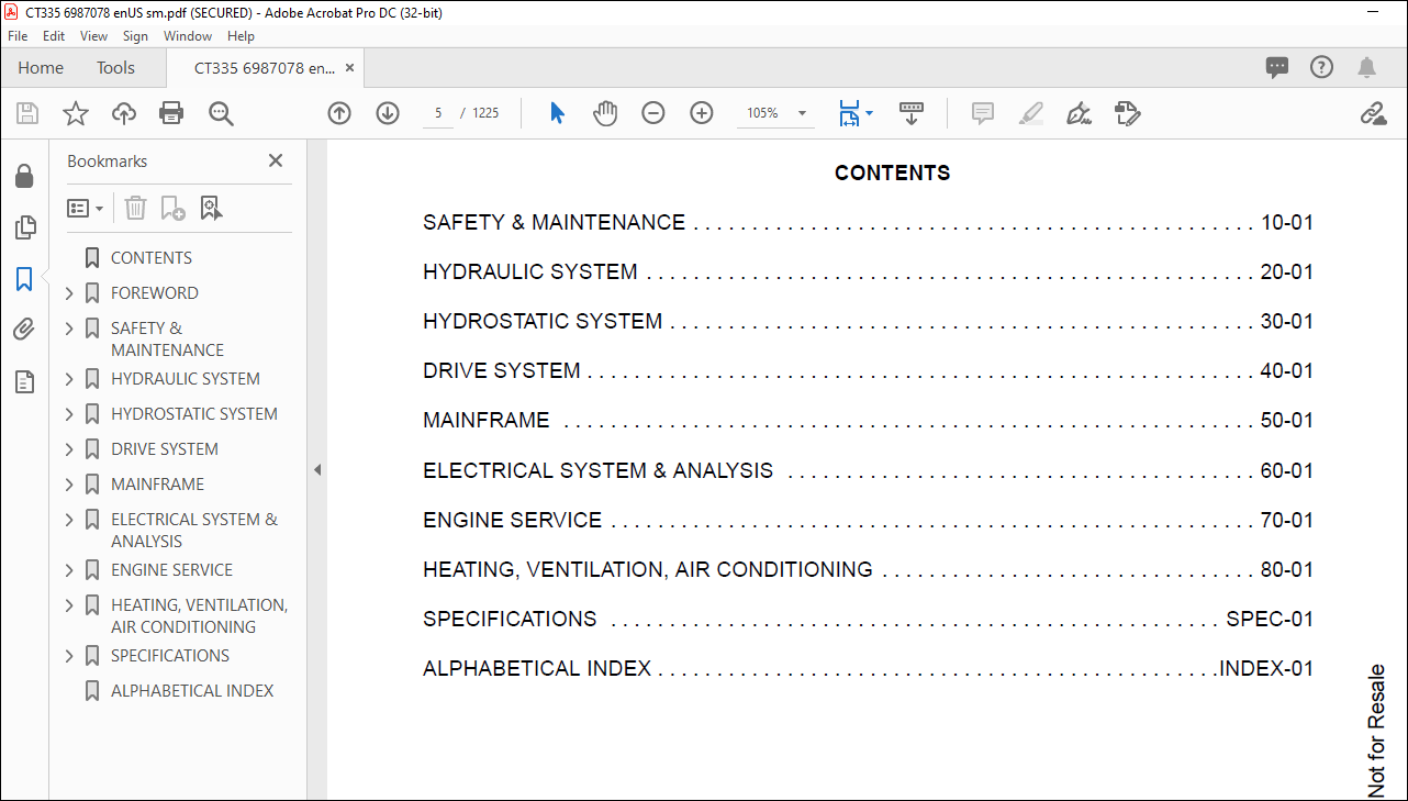
CONTENTS 5
FOREWORD 7
FOREWORD 9
SAFETY INSTRUCTIONS 11
Use Safety Rules 12
Safety Rules For Power Take-Off (PTO) Driven Implements 13
Compact Tractor Requirements and Capabilities 13
FIRE PREVENTION 14
Maintenance 14
Operation 14
Electrical 14
Hydraulic System 14
Fueling 14
Starting 14
Spark Arrester Exhaust System 14
Welding And Grinding 15
Fire Extinguishers 15
SERIAL NUMBER LOCATIONS 16
Compact Tractor Serial Number 16
Engine Serial Number 16
Loader Serial Number (Optional) 16
Loader Serial Number (Optional) (Cont’d) 17
DELIVERY REPORT 18
COMPACT TRACTOR IDENTIFICATION 19
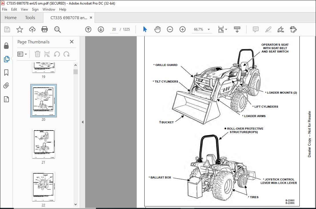
COMPACT TRACTOR IDENTIFICATION (WITH OPTIONAL LOADER AND REAR BALLAST) 20
COMPACT TRACTOR IDENTIFICATION (WITH OPTIONAL THREE-POINT IMPLEMENT AND FRONT BALLAST) 21
COMPACT TRACTOR IDENTIFICATION (WITH OPTIONAL CAB) 22
SAFETY & MAINTENANCE 23
SUPPORTING THE COMPACT TRACTOR ON JACKSTANDS 27
Procedure 27
ENGINE COVER 29
Opening And Closing 29
SEAT BELT 31
Inspection And Maintenance 31
TRANSPORTING THE COMPACT TRACTOR ON A TRAILER 33
Loading And Unloading 33
Fastening 34
TOWING THE COMPACT TRACTOR 37
Procedure 37
AXLE TOE IN (HST MODELS) 39
Inspection And Maintenance 39
AXLE TOE IN (SST MODELS) 41
Adjustment 41
SERVICE SCHEDULE 43
Chart 43
AIR CLEANER SERVICE 45
Replacing Filter Element 45
FRESH AIR FILTERS (WITH CAB) 47
Removal And Installation 47
ENGINE COOLING SYSTEM 49
Checking Level 49
Cleaning 50
Hoses And Clamps 50
Removing And Replacing Coolant 51
FUEL SYSTEM 53
Fuel Specifications 53
Biodiesel Blend Fuel 53
Filling The Fuel Tank 54
Fuel Filter 55
Removing Air From The Fuel System 56
Filling A Portable Fuel Container 56
ENGINE LUBRICATION SYSTEM 57
Checking And Adding Engine Oil 57
Engine Oil Chart 57
Removing And Replacing Oil And Filter 58
HYDRAULIC / HYDROSTATIC / TRANSMISSION SYSTEM 61
Checking And Adding Fluid 61
Transmission / Differential Fluid Chart 61
Removing And Replacing Hydraulic / Hydrostatic / Transmission Filters 62
Removing And Replacing Hydraulic / Transmission Fluid 63
Hoses And Clamps 64
FRONT AXLE 67
Checking And Adding Lubricant 67
Removing And Replacing Lubricant 68
Axle Pivot 68
SPARK ARRESTER MUFFLER 69
Cleaning Procedure 69
COMPACT TRACTOR STORAGE AND RETURN TO SERVICE 71
Storage 71
Return To Service 71
ALTERNATOR BELT 73
Belt Adjustment 73
Belt Replacement 73
AIR CONDITIONING BELT 75
Belt Adjustment 75
Belt Replacement 75
LUBRICATING THE COMPACT TRACTOR 77
Lubrication Locations 77
TIRE MAINTENANCE 81
Front Wheel Nuts / Bolts 81
Rear Wheel Nuts / Bolts 81
Mounting 81
Wheel Spacing (AG And Industrial Tires Only) 82
PIVOT PINS 83
Inspection And Maintenance 83
SAFETY INTERLOCK SYSTEM – NEUTRAL START 85
Inspection And Maintenance (HST) 85
Inspection And Maintenance (SST) 86
SAFETY INTERLOCK SYSTEM – OPERATING 87
Inspection And Maintenance (HST) 87
Inspection And Maintenance (SST) 88
PARKING BRAKE SYSTEM 89
Inspection And Maintenance 89
BRAKE SYSTEM 91
Inspection And Maintenance 91
Adjusting 93
TRAVEL CONTROL PEDAL (HST ONLY) 95
Inspection And Maintenance 95
F-N-R LEVER (SST ONLY) 97
Inspection And Maintenance 97
CRUISE CONTROl (HST ONLY) 99
Inspection And Maintenance 99
CLUTCH PEDAL (SST ONLY) 101
Inspection And Maintenance 101
SPEED RANGE LEVER (HST ONLY) 103
Calibration 103
BOB-TACH (HAND LEVER) 105
Inspection And Maintenance 105
CLUTCH PEDAL AND HOUSING (SST ONLY) 107
Draining Water 107
Storage Position 107
DIFFERENTIAL LOCK 109
Inspection And Maintenance 109
Adjustment 109
HYDRAULIC SYSTEM 111
HYDRAULIC\HYDROSTATIC SCHEMATICS 115
HYDRAULIC SYSTEM INFORMATION 119
Glossary Of Hydraulic / Hydrostatic Symbols For Compact Tractors 119
Troubleshooting The Hydraulic Circuit 123
Troubleshooting The Joystick Valve Circuit 123
Troubleshooting The Power Lift Circuit 124
Troubleshooting The Steering Circuit 125
MAIN RELIEF VALVE 127
Testing Information 127
Testing And Adjusting The Main Relief Valve 127
HYDRAULIC PUMP 133
Removal And Installation 133
Parts Identification 135
Disassembly 136
Assembly 140
STEERING VALVE 145
Removal And Installation 145
Parts Identification 146
Disassembly 147
Inspection 152
Assembly 152
STEERING VALVE TESTING 159
Relief Pressure 159
Working Pressure 160
STEERING CYLINDER 161
Removal And Installation 161
Parts Identification 163
Disassembly And Assembly 164
STEERING CYLINDER (SST MODELS) 165
Removal And Installation 165
Parts Identification 168
Disassembly 169
Assembly 171
RIGHT JOYSTICK (WITHOUT CAB) 177
Removal And Installation 177
Parts Identification 179
Disassembly And Assembly 180
Adjustment 182
RIGHT JOYSTICK (WITH CAB) 185
Removal And Installation 185
Parts Identification 187
Disassembly And Assembly 188
Adjustment 190
RIGHT JOYSTICK VALVE (IF EQUIPPED) 191
Removal And Installation 191
Parts Identification 194
Disassembly 195
Inspection 199
Assembly 199
REAR PTO 203
Engagement Testing 203
OIL COOLER (HST MODELS) 205
Removal And Installation 205
THREE POINT HITCH HOUSING 207
Removal And Installation 207
AUXILIARY CONTROL VALVE 211
End Cap Section Disassembly And Assembly 211
Valve Section Parts Identification 213
Valve Section Disassembly And Assembly 214
Detent Assembly 218
ROCK SHAFT 221
Removal And Installation 221
MLS VALVE 223
Removal And Installation 223
Parts Identification 224
Disassembly And Assembly 225
Adjustment (HST Models) 234
Adjustment (SST Models) 236
THREE POINT CYLINDER 239
Disassembly And Assembly 239
Inspection 242
THREE POINT CYLINDER CONTROL 245
Disassembly And Assembly 245
Adjusting The Position Control Lever (HST Models) 251
Adjusting The Position Control Lever (SST Models) 253
MODULATOR VALVE 255
Removal And Installation 255
Parts Identification 257
Disassembly And Assembly 258
FRONT WHEEL DRIVE 263
Engagement Testing 263
Adjustment 263
CYLINDER (Lift) (EARLY MODELS) 265
Testing 265
Removal And Installation 265
Parts Identification 268
Disassembly 269
Assembly 271
CYLINDER (LIFT) (LATE MODELS) 275
Testing 275
Removal And Installation 275
Parts Identification 278
Disassembly 279
Assembly 281
CYLINDER (TILT) (EARLY MODELS) 285
Testing 285
Removal And Installation 285
Parts Identification 287
Disassembly 288
Assembly 290
CYLINDER (TILT) (LATE MODELS) 295
Testing 295
Removal And Installation 295
Parts Identification 297
Disassembly 298
Assembly 300
HYDROSTATIC SYSTEM 303
HYDROSTATIC SYSTEM INFORMATION (HST MODELS) 305
Troubleshooting Chart 305
HYDROSTATIC PUMP (HST MODELS) 307
Removal And Installation 307
Parts Identification 313
Disassembly 315
Inspection 332
Assembly 335
Hydrostatic Pump Start-Up 354
HYDROSTATIC PUMP TESTING (HST MODELS) 355
Charge Pressure Testing 355
Hydrostatic Drive Pressure Testing 356
Neutral Valves 358
TRAVEL CONTROL PEDALS (HST MODELS) 359
Removal And Installation 359
TRAVEL CONTROL PEDAL LINKAGE (HST MODELS) 361
Removal And Installation 361
TRAVEL CONTROL PEDAL PIVOT ARMS (HST MODELS) 363
Removal And Installation 363
DRIVE SYSTEM 365
SERVICE BRAKE 371
Troubleshooting Chart 371
Description 371
Inspection And Maintenance 372
Adjusting 374
Stop Switch Adjustment (HST Models) 375
Stop Switch Adjustment (SST Models) 377
BRAKE PEDAL ASSEMBLY 379
Removal And Installation 379
BRAKE / CLUTCH PEDAL ASSEMBLY (SST MODELS) 383
Removal And Installation 383
DRIVESHAFT (EARLY MODELS) 387
Removal And Installation 387
DRIVESHAFT (LATER MODELS) 389
Removal And Installation 389
AXLE CASE 391
Removal And Installation 391
Parts Identification 393
Disassembly And Assembly 394
BRAKE CASE 399
Removal And Installation 399
Parts Identification 401
Disassembly And Assembly 402
Inspection 405
TRANSMISSION (HST MODELS) 407
Troubleshooting Chart 407
Middle Case / PTO Clutch Group Parts Identification 408
Middle Case / PTO Clutch Group Disassembly 409
Middle Case / PTO Clutch Group Inspection 416
Middle Case / PTO Countershaft Group Parts Identification 417
Middle Case / PTO Countershaft Group Disassembly 418
Middle Case / PTO Countershaft Group Inspection 419
Middle Case / 23 Gear Shaft Group Parts Identification 420
Middle Case / 23 Gear Shaft Group Disassembly 421
Middle Case / 23 Gear Shaft Group Inspection 421
Middle Case / Countershaft Group Parts Identification 422
Middle Case / Countershaft Group Disassembly 423
Middle Case / Countershaft Group Inspection 424
Bearing Cover / Shift Links Parts Identification 425
Bearing Cover / Shift Links Disassembly 426
Bearing Cover / Shift Links Inspection 430
Pinion Shaft Group Parts Identification 431
Pinion Shaft Group Disassembly 432
Pinion Shaft Group Inspection 438
PTO Shaft Group Parts Identification 439
PTO Shaft Group Disassembly 440
PTO Shaft Group Inspection 443
Range Shifter Shaft Group Parts Identification 444
Range Shifter Shaft Group Disassembly 445
Range Shifter Shaft Group Inspection 446
PTO 15 Gear Shaft Group Parts Identification 447
PTO 15 Gear Shaft Group Disassembly 448
PTO 15 Gear Shaft Group Inspection 450
Idle Shaft Group Parts Identification 451
Idle Shaft Group Disassembly 452
Idle Shaft Group Inspection 456
Front Wheel Drive Shaft Group Parts Identification 457
Front Wheel Drive Shaft Group Disassembly 458
Front Wheel Drive Shaft Group Inspection 460
Rear PTO Shaft Group Parts Identification 461
Rear PTO Shaft Group Disassembly 462
Rear PTO Shaft Group Inspection 464
Differential Parts Identification 465
Differential Disassembly 466
Differential Inspection 473
Differential Assembly 474
Rear PTO Shaft Group Assembly 482
Front Wheel Drive Shaft Group Assembly 484
Idle Shaft Group Assembly 486
PTO 15 Gear Shaft Group Assembly 489
Range Shifter Shaft Group Assembly 492
PTO Shaft Group Assembly 493
Pinion Shaft Group Assembly 496
Bearing Cover / Shift Links Assembly 502
Middle Case / Countershaft Group Assembly 508
Middle Case / 23 Gear Shaft Group Assembly 510
Middle Case / PTO Countershaft Group Assembly 511
Middle Case / PTO Clutch Group Assembly 512
TRANSMISSION (SST MODELS) 519
Troubleshooting Chart 519
Transmission Case Removal 520
Transmission Case Parts Identification 524
Transmission Case Disassembly 525
Bearing Cover / PTO Countershaft Parts Identification 532
Bearing Cover / PTO Countershaft Disassembly 533
Middle Case / 23 Gear Shaft Group Inspection 533
Bearing Cover / PTO Countershaft Inspection 534
Bearing Cover / PTO Driveshaft Parts Identification 535
Bearing Cover / PTO Driveshaft Disassembly 536
Bearing Cover / PTO Driveshaft Inspection 536
Bearing Cover / Shift Links Parts Identification 537
Bearing Cover / Shift Links Disassembly 538
Bearing Cover / Shift Links Inspection 540
Bearing Cover / Countershaft Parts Identification 541
Bearing Cover / Countershaft Disassembly 542
Bearing Cover / Countershaft Disassembly (Cont’d) 544
Bearing Cover / Countershaft Inspection 549
Bearing Cover / Main Shaft Parts Identification 550
Bearing Cover / Main Shaft Disassembly 551
Bearing Cover / Main Shaft Inspection 551
Middle Case Removal 552
Middle Case / Bearing Cover Removal 553
Middle Case / Shift Link Parts Identification 554
Middle Case / Shift Link Disassembly 555
Middle Case / Shift Link Inspection 557
Middle Case / 19 Gear Shaft Parts Identification 558
Middle Case / 19 Gear Shift Disassembly 559
Middle Case / 19 Gear Shaft Inspection 559
Middle Case / Shuttle Shaft Parts Identification 560
Middle Case / Shuttle Shaft Disassembly 561
Middle Case / Shuttle Shaft Inspection 568
Middle Case / 23/20 Gear Shaft Parts Identification 569
Middle Case / 23-20 Gear Shaft Disassembly 570
Middle Case / 23-30 Gear Shaft Inspection 570
Middle Case / PTO Clutch Parts Identification 571
Middle Case / PTO Clutch Disassembly 572
Middle Case / PTO Clutch Inspection 576
Middle Case Bearing Cover / Shift Links Parts Identification 577
Middle Case Bearing Cover / Shift Links Disassembly 578
Middle Case Bearing Cover / Shift Links Inspection 582
Pinion Shaft Parts Identification 583
Pinion Shaft Disassembly 584
Pinion Shaft Inspection 590
PTO Shaft Parts Identification 591
PTO Shaft Disassembly 592
PTO Shaft Inspection 595
Range Shifter Shaft Parts Identification 596
Range Shifter Shaft Disassembly 597
Range Shifter Shaft Inspection 598
PTO 15 Gear Shaft Parts Identification 599
PTO 15 Gear Shaft Disassembly 600
PTO 15 Gear Shaft Inspection 602
Idle Shaft Parts Identification 603
Idle Shaft Disassembly 604
Idle Shaft Inspection 608
Front Wheel Drive Shaft Parts Identification 609
Front Wheel Drive Shaft Disassembly 610
Front Wheel Drive Shaft Inspection 612
Rear PTO Shaft Parts Identification 613
Rear PTO Shaft Disassembly 614
Rear PTO Shaft Inspection 616
Differential Parts Identification 617
Differential Disassembly 618
Differential Inspection 625
Differential Assembly 626
Rear PTO Shaft Assembly 634
Front Wheel Drive Shaft Assembly 636
Idle Shaft Assembly 638
PTO 15 Gear Shaft Assembly 641
Range Shifter Shaft Assembly 644
PTO Shaft Assembly 645
Pinion Shaft Assembly 648
Middle Case Bearing Cover / Shift Links Assembly 654
Middle Case / PTO Clutch Assembly 660
Middle Case / 23-20 Gear Shaft Assembly 664
Middle Case / Shuttle Shaft Assembly 665
Middle Case / 19 Gear Shaft Assembly 672
Middle Case / Shift Link Assembly 673
Middle Case / Bearing Cover Installation 676
Middle Case Installation 676
Bearing Cover / Main Shaft Assembly 677
Bearing Cover / Countershaft Assembly 678
Bearing Cover / Shift Links Assembly 686
Bearing Cover / PTO Driveshaft Assembly 691
Bearing Cover / PTO Countershaft Assembly 692
Transmission Case Assembly 693
Transmission Case Installation 701
FRONT AXLE 705
Removal And Installation 705
FRONT AXLE (SST MODELS) 709
Removal And Installation 709
AXLE AND DIFFERENTIAL 713
Troubleshooting Chart 713
Front Axle Cover Parts Identification 714
Front Axle Cover Disassembly 715
Front Axle Cover Inspection 718
Front Axle Case Group Parts Identification 719
Front Axle Case Group Disassembly 720
Bevel Gear Case Group Parts Identification 723
Bevel Gear Case Group Disassembly 724
Bevel Gear Case Group Inspection 726
Axle Shaft Group Parts Identification 727
Axle Shaft Group Disassembly 728
Axle Shaft Group Inspection 729
Axle Support Removal 730
Pinion Shaft Removal 732
Pinion Shaft Parts Identification 733
Pinion Shaft Disassembly 734
Pinion Shaft Inspection 734
Differential Removal 735
Differential Parts Identification 736
Differential Disassembly 737
Differential Inspection 740
Differential Assembly 741
Differential Installation 745
Pinion Shaft Assembly 746
Pinion Shaft Installation 747
Axle Support Installation 749
Axle Shaft Group Assembly 751
Bevel Gear Case Group Assembly 753
Front Axle Case Group Assembly 755
Front Axle Cover Assembly 759
AXLE AND DIFFERENTIAL (SST MODELS) 763
Troubleshooting Chart 763
Front Axle Cover Parts Identification 764
Front Axle Cover Disassembly 765
Front Axle Cover Inspection 768
Front Axle Case Group Parts Identification 769
Front Axle Case Group Disassembly 770
Bevel Gear Case Group Parts Identification 773
Bevel Gear Case Group Disassembly 774
Bevel Gear Case Group Inspection 776
Axle Shaft Group Parts Identification 777
Axle Shaft Group Disassembly 778
Axle Shaft Group Inspection 779
Axle Support Removal 780
Pinion Shaft Removal 782
Pinion Shaft Parts Identification 783
Pinion Shaft Disassembly 784
Pinion Shaft Inspection 784
Differential Removal 785
Differential Parts Identification 786
Differential Disassembly 787
Differential Inspection 790
Differential Assembly 791
Differential Installation 795
Pinion Shaft Assembly 796
Pinion Shaft Installation 797
Axle Support Installation 799
Axle Shaft Group Assembly 801
Bevel Gear Case Group Assembly 803
Front Axle Case Group Assembly 805
Front Axle Cover Assembly 809
STEERING AXLE ADJUSTMENT (HST MODELS) 813
Toe-In Checking 813
Toe-In Adjustment 813
Rocking Force 813
Steering Angle Adjustment 814
STEERING AXLE ADJUSTMENT (SST MODELS) 815
Rocking Force 815
Steering Angle Adjustment 816
Toe-In Checking 816
Toe-In Adjustment 817
SEPARATING THE TRACTOR (HST MODELS) 819
Procedure 819
SEPARATING THE TRACTOR (SST MODELS) 825
Procedure 825
MAINFRAME 831
OPERATOR SEAT 835
Removal And Installation 835
CONSOLE COVER (WITHOUT CAB) 837
Left Side Removal And Installation 837
Right Side Removal And Installation 838
CONSOLE COVER (WITH CAB) 839
Left Side Removal And Installation 839
Right Side Removal And Installation 840
TRANSMISSION CASE (HST MODELS) 843
Removal And Installation 843
TRANSMISSION CASE (SST MODELS) 847
Removal And Installation 847
FUEL TANK 849
Removal And Installation 849
MID PTO CONTROL 853
Lever Removal And Installation 853
SPLASH BOARD 855
Removal And Installation 855
FLOOR MAT (HST MODELS) 857
Removal And Installation 857
FLOOR MAT (SST MODELS) 859
Removal And Installation 859
FLOOR PLATE 861
Removal And Installation 861
ENGINE COVER 863
Gas Cylinder Removal And Installation 863
Removal And Installation 863
GRILLE 865
Removal And Installation 865
ENGINE SIDE COVER 867
Removal And Installation 867
FENDER ASSEMBLY (WITHOUT CAB) (HST MODELS) 869
Removal And Installation 869
Fender Mount Removal And Installation 875
FENDER ASSEMBLY (SST MODELS) 877
Removal And Installation 877
Fender Mount Removal And Installation 883
FENDER (WITHOUT CAB) 885
Removal And Installation 885
FENDER (WITH CAB) 887
Removal And Installation 887
FIREWALL (WITHOUT CAB) (HST MODELS) 889
Removal And Installation 889
FIREWALL (WITH CAB) (HST MODELS) 893
Removal And Installation 893
FIREWALL (SST MODELS) 899
Removal And Installation 899
ROPS 903
Removal And Installation 903
Bracket Removal And Installation 904
PTO SAFETY SHIELD 905
Removal And Installation 905
DRAW BAR 907
Removal And Installation 907
DRAW BAR ASSEMBLY 909
Removal And Installation 909
THREE POINT HITCH LOWER LINKS 911
Left Side Removal And Installation 911
Right Side Removal And Installation 912
Top Link Assembly Removal And Installation 913
FRONT WORK LIGHT MOUNT (WITH CAB) 915
Removal And Installation 915
CAB COVER 917
Removal And Installation 917
CAB POST COVER 919
Removal And Installation 919
INNER FENDER ACCESS COVER (With Cab) 923
Removal And Installation 923
CAB (HST MODELS) 925
Removal And Installation 925
Door Removal And Installation 933
Windshield Removal And Installation 934
Front Lower Window Removal And Installation 936
Rear Window Removal And Installation 937
Side Window Removal And Installation 938
Door Glass Removal And Installation 938
HEADLINER 941
Removal And Installation 941
BOB-TACH (HAND LEVER) 943
Description 943
Removal And Installation 943
Parts Identification 944
Lever And Wedge Disassembly And Assembly 945
ELECTRICAL SYSTEM & ANALYSIS 947
ELECTRICAL SCHEMATICS 949
ELECTRICAL SYSTEM INFORMATION 952
Glossary Of Electrical Symbols 952
Electrical Component Location (Without Cab) (HST Models) 955
Electrical Component Location (With Cab) (HST Models) 956
Electrical Component Location (SST Models) 957
Troubleshooting 958
Description 959
Fuse And Relay Location – Engine Compartment 959
Fuse And Relay Location – Cab (If Equipped) 960
Fuse And Relay Location – Instrument Panel – HST Models 961
Fuse And Relay Location – Instrument Panel – SST Models 962
BATTERY 964
Removing And Installing Battery 964
Battery Maintenance 965
Using A Booster Battery (Jump Starting) 966
ALTERNATOR 968
Belt Adjustment 968
Belt Replacement 968
Charging System Inspection 969
Alternator Voltage Testing 970
Low Voltage Testing 970
High Voltage Testing 971
Removal And Installation 972
Parts Identification 973
STARTER 974
Testing 974
Removal And Installation 975
Parts Identification 976
HOOD LIGHTS 978
Removal And Installation 978
Bulb Removal And Installation 978
REAR LIGHTS 980
Removal And Installation 980
Bulb Removal And Installation 981
FRONT LIGHTS (WITH CAB) 982
Removal And Installation 982
Bulb Removal And Installation 983
SEAT SENSOR 984
Removal And Installation 984
FUEL LEVEL SENDER 986
Removal And Installation 986
INSTRUMENT PANEL 988
Removal And Installation 988
STEERING COLUMN COVER 990
Removal And Installation 990
PTO SWITCH (REAR) 992
Inspection And Maintenance 992
Removal And Installation 992
PTO LEVER (MID) (IF EQUIPPED) 994
Inspection And Maintenance 994
PTO Switch Removal And Installation 995
Adjustment 996
HORN 998
Removal And Installation 998
REAR WORK LIGHT (WITH CAB) 1000
Removal And Installation 1000
Disassembly And Assembly 1000
FRONT WORK LIGHT (WITH CAB) 1002
Removal And Installation 1002
Disassembly And Assembly 1002
CRUISE CONTROL (HST ONLY) 1004
Inspection And Maintenance 1004
Switch Removal And Installation 1005
Magnet Removal And Installation 1005
Controller Removal And Installation 1005
SPEED RANGE LEVER (HST ONLY) 1006
Calibration 1006
Controller Removal And Installation 1007
FORWARD – NEUTRAL – REVERSE (F-N-R) LEVER (SST MODELS) 1008
Removal And Installation 1008
F-N-R Lever Disassembly And Assembly 1009
ENGINE SERVICE 1010
ENGINE INFORMATION 1014
Description 1014
Troubleshooting 1023
Engine Removal And Installation 1026
Compression – Checking 1033
ENGINE SPEED CONTROL 1034
Cable Removal And Installation 1034
Lever Removal And Installation 1036
ENGINE SPEED CONTROL PEDAL (SST MODELS) 1038
Removal And Installation 1038
Cable Removal And Installation 1038
SPARK ARRESTER MUFFLER 1040
Removal And Installation 1040
AIR CLEANER 1042
Removal And Installation 1042
ENGINE COOLING SYSTEM 1044
Description 1044
Radiator Removal And Installation 1045
Water Pump Removal And Installation 1049
Water Pump Disassembly And Assembly 1049
Thermostat Housing Removal And Installation 1050
Testing The Thermostat 1050
LUBRICATION SYSTEM 1052
Description 1052
Oil Pan Removal And Installation 1053
Oil Pump Removal And Installation 1053
Oil Pump Inspection 1054
Engine Oil Pressure – Testing 1055
Oil Filter 1055
FUEL SYSTEM 1056
Description 1056
Fuel Camshaft Removal And Installation 1057
Fuel Shutoff Solenoid Checking 1057
Fuel Shutoff Solenoid Removal And Installation 1058
Fuel Injection Pump Removal And Installation 1058
Fuel Injection Pump Timing 1064
Fuel Injector Removal And Installation 1067
Fuel Injector Nozzle Pressure – Checking 1071
Nozzle Spray Condition 1072
Valve Seat Tightness 1073
Bleeding The Fuel System 1074
CYLINDER HEAD 1076
Glow Plug – Testing 1076
Glow Plug Removal And Installation 1077
Valve Clearance Adjustment 1078
Valve Timing – Checking 1079
Cylinder Head Removal And Installation 1079
Cylinder Head Bolt Tightening Procedure 1082
Cylinder Head Disassembly And Assembly 1083
Cylinder Head Servicing 1083
Cylinder Head Top Clearance 1084
Valve Guide – Checking 1084
Reconditioning The Valve And Valve Seat 1086
Valve Spring 1087
Valve Tappets 1088
Rocker Arm And Shaft – Checking 1088
CRANKSHAFT AND PISTONS 1090
Piston And Connecting Rod Removal And Installation 1090
Piston And Connecting Rod – Servicing 1092
Cylinder Bore – Checking 1094
Connecting Rod – Alignment 1094
Crankshaft And Bearings Removal And Installation 1095
Crankshaft And Bearings – Servicing 1097
CAMSHAFT AND TIMING GEARS 1100
Timing Gearcase Cover Removal And Installation 1100
Timing Gears Backlash – Checking 1102
Idler Gear And Shaft Removal And Installation 1103
Camshaft – Servicing 1105
Idler Gear And Shaft – Servicing 1106
FLYWHEEL AND HOUSING (HST MODELS) 1108
Flywheel Removal And Installation 1108
Flywheel Housing Removal And Installation 1109
FLYWHEEL AND HOUSING (SST MODELS) 1110
Flywheel Removal And Installation 1110
Flywheel Housing Removal And Installation 1111
FAN 1112
Removal And Installation 1112
CLUTCH ASSEMBLY (SST MODELS) 1114
Troubleshooting Chart 1114
Removal And Installation 1115
Clutch Disc Inspection 1116
Pressure Plate Inspection 1116
Clutch Pedal Play And Stopper Bolt Adjustment 1116
CLUTCH LEVER (SST MODELS) 1118
Parts Identification 1118
Disassembly 1119
Inspection 1121
Assembly 1122
HEATING, VENTILATION, AIR CONDITIONING 1124
HEATER COIL 1126
Removal And Installation 1126
BLOWER FAN 1128
Removal And Installation 1128
HEATER VALVE 1130
Removal And Installation 1130
AIR CONDITIONING SYSTEM FLOW 1133
Principals 1133
Chart 1134
COMPONENTS 1136
Identification 1136
SAFETY 1140
Safety Equipment 1140
REGULAR MAINTENANCE 1142
Fresh Air Filter 1142
Air Conditioning Belt 1142
Cleaning The Condenser 1142
RESISTOR 1144
Removal And Installation 1144
GENERAL AIR CONDITIONING SERVICE GUIDELINES 1146
Compressor Oil 1146
Compressor Oil Check 1146
Component Replacement And Refrigeration Leaks 1148
SYSTEM TROUBLESHOOTING CHART 1150
Blower Motor Does Not Operate 1150
Gauge Pressure Related Troubleshooting 1151
TEMPERATURE / PRESSURE 1154
Chart 1154
AIR CONDITIONING SERVICE 1156
Chart 1156
SYSTEM CHARGING AND RECLAMATION 1158
Reclamation Procedure 1158
Charging Procedure With A Manifold Gauge Set 1161
COMPRESSOR 1164
Removal And Installation 1164
CONDENSER 1166
Removal And Installation 1166
RECEIVER / DRIER 1170
Removal And Installation 1170
HVAC CONTROL PANEL 1172
Removal And Installation 1172
PRESSURE SWITCH 1174
Removal And Installation 1174
EVAPORATOR / HEATER UNIT 1176
Removal And Installation 1176
EVAPORATOR / HEATER UNIT COVER 1180
Removal And Installation 1180
FRONT AIR DUCT 1182
Removal And Installation 1182
SIDE AIR DUCT 1184
Removal And Installation 1184
THERMOSTAT 1186
Removal And Installation 1186
EXPANSION VALVE 1188
Removal And Installation 1188
EVAPORATOR 1190
Removal And Installation 1190
SPECIFICATIONS 1192
CT335 SPECIFICATIONS (HST) 1194
Compact Tractor Loader Lift Capacities 1194
Ballast (Rear) 1194
Three-Point Hitch Specifications 1195
Towing Weight 1195
Maximum Drawbar Tongue Weight 1195
Ballast (Front) 1195
Dimensions (Standard Machine) 1196
Dimensions (With Optional Loader, S/N AL4E00101 & Above, S/N AKPM00101 & Above) 1197
Dimensions (With Optional Loader, S/N AE3C00101 & Above) 1198
Performance 1199
Controls 1199
Engine 1200
Hydraulic System 1200
Electrical 1200
Power Take-Off (PTO) System (Rear-PTO) 1201
Power Take-Off (PTO) System (Mid-PTO Optional) 1201
Drive System 1201
Steering 1202
Capacities 1202
Tires 1202
Loader (If Equipped) 1202
CT335 SPECIFICATIONS (SST) 1204
Compact Tractor Loader Lift Capacities 1204
Ballast (Rear) 1204
Three-Point Hitch Specifications 1205
Towing Weight 1205
Maximum Drawbar Tongue Weight 1205
Ballast (Front) 1205
Dimensions (Standard Machine) 1206
Dimensions (With Optional Loader, S/N AL4E00101 & Above, S/N AKPM00101 & Above) 1207
Dimensions (With Optional Loader, S/N AE3C00101 & Above) 1208
Performance 1209
Controls 1209
Engine 1210
Hydraulic System 1210
Electrical 1210
Power Take-Off (PTO) System (Rear-PTO) 1211
Power Take-Off (PTO) System (Mid-PTO Optional) 1211
Drive System 1212
Steering 1213
Capacities 1213
Tires 1213
Loader (If Equipped) 1213
TORQUE SPECIFICATIONS FOR BOLTS 1214
Torque For General SAE Bolts 1214
Torque For General Metric Bolts 1215
HYDRAULIC FLUID SPECIFICATIONS 1216
Specifications 1216
CONVERSIONS 1218
Decimal And Millimeter Equivalent Chart 1218
U S To Metric Conversion Chart 1219
FUEL, COOLANT AND LUBRICANTS 1220
Chart 1220
ALPHABETICAL INDEX 1222
IMAGES PREVIEW OF THE MANUAL:
VIDEO PREVIEW OF THE MANUAL:
PLEASE NOTE:
- This is the same manual used by the dealers to diagnose and troubleshoot your vehicle
- You will be directed to the download page as soon as the purchase is completed. The whole payment and downloading process will take anywhere between 2-5 minutes
- Need any other service / repair / parts manual, please feel free to contact [email protected] . We still have 50,000 manuals unlisted
s.m


