

Bobcat Chipper WC-5A WC-8A WC-8B Service Manual 6900901 (12-14) – PDF DOWNLOAD
FILE DETAILS:
Bobcat Chipper WC-5A WC-8A WC-8B Service Manual 6900901 (12-14) – PDF DOWNLOAD
Language : English
Pages :200
Downloadable : Yes
File Type : PDF
DESCRIPTION:
Bobcat Chipper WC-5A WC-8A WC-8B Service Manual 6900901 (12-14) – PDF DOWNLOAD
(WC-5A Chipper) S/N 912900101 & Above
(WC-8A Chipper) S/N 739500101 & Above
(WC-8B Chipper) S/N A02B00101 & Above
the chipper. Chipper problems can be affected by a hydraulic system that is not operating to specifications. Connect a flow
meter to the machine to check the hydraulic pump output, relief valve setting and tube lines to check flow and pressure.
(See the machine’s Service Manual for the correct procedure to connect the flow meter.)
Use the following troubleshooting chart to locate and correct problems which most often occur with the attachment.
IMAGES PREVIEW OF THE MANUAL:

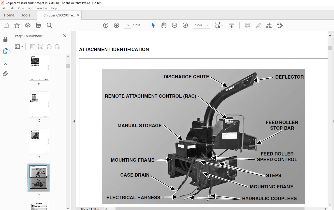
TABLE OF CONTENTS:
Bobcat Chipper WC-5A WC-8A WC-8B Service Manual 6900901 (12-14) – PDF DOWNLOAD
MAINTENANCE SAFETY 3
CONTENTS 5
FOREWORD 7
SERIAL NUMBER LOCATION 9
Attachment Serial Number 9
DELIVERY REPORT 10
MANUAL STORAGE LOCATION 11
ATTACHMENT IDENTIFICATION 12
SAFETY AND MAINTENANCE 13
TROUBLESHOOTING 15
Chart 15
DAILY INSPECTION 17
Attachment Mounting Frame 17
Feed Roller Stop Bar Activation Point (WC-8B only) 17
Bob-Tach 18
LUBRICATION 21
Lubrication Locations 21
SERVICE SCHEDULE 23
Chart (WC-5A And WC-8A Chipper) 23
Chart (WC-8B Chipper) 24
CHIPPER BLADES 25
Setting Chipper Blade Clearance 25
Sharpening The Chipper Blades 27
ATTACHMENT STORAGE AND RETURN TO SERVICE 29
Storage 29
Return To Service 29
FEED ROLLER SUPPORT 31
Procedure 31
FEED ROLLER STOP BAR ACTIVATION POINT (WC- 8B ONLY) 33
Description 33
Adjustment 33
HYDRAULIC SYSTEM 35
HYDRAULIC CONTROL VALVE (S/N 912900101 & ABOVE, S/N 739500101 & ABOVE) 37
Removal And Installation 37
Parts Identification 39
Disassembly 40
Assembly 46
HYDRAULIC CONTROL VALVE (S/N A02B00101 & ABOVE) 53
Removal And Installation 53
Parts Identification 54
Disassembly 55
Assembly 61
SHUT-OFF VALVE (S/N A02B00101 & ABOVE) 67
Removal And Installation 67
Parts Identification 68
Disassembly 69
Assembly 71
HYDRAULIC MOTOR (CHIPPER WHEEL) (S/N 912900101 & ABOVE) 73
Removal And Installation 73
Parts Identification 75
Disassembly And Assembly 76
Inspection 79
HYDRAULIC MOTOR (CHIPPER WHEEL) (S/N 739500101 & ABOVE) 81
Removal And Installation 81
Parts Identification 83
Disassembly And Assembly 84
Inspection 87
HYDRAULIC MOTOR (CHIPPER WHEEL) (S/N A02B00101 & ABOVE) 89
Removal And Installation 89
Parts Identification 91
Disassembly 92
Assembly 95
HYDRAULIC MOTOR (FEED ROLLER) (S/N 912900101 & Above, S/N 739500164 & Above, S/N A02B00101 & Above) 101
Removal And Installation 101
Parts Identification 103
Disassembly And Assembly 104
Inspection 108
Timing The Hydraulic Motor 109
HYDRAULIC MOTOR (FEED ROLLER) (S/N 739500163 & Below) 111
Removal And Installation 111
Parts Identification 112
Disassembly 113
Inspection 118
Assembly 118
HYDRAULIC PUMP (S/N A02B00101 & ABOVE) 125
Removal And Installation 125
Parts Identification 128
Disassembly 129
Inspection 132
Assembly 132
MAINFRAME 137
CHIPPER BLADES (WC-5A) 139
Removal And Installation 139
Setting Chipper Blade Clearance 141
CHIPPER BLADES (WC-8A AND WC-8B) 143
Removal And Installation 143
Setting Chipper Blade Clearance 145
CHIPPER WHEEL 147
Bearing Removal And Installation (WC-5A And WC- 8A) 147
Bearing Removal And Installation (WC-8B) 149
Housing Removal And Installation 151
FEED ROLLER CONTROL 155
Removal And Installation 155
Bearing Removal And Installation 156
DISCHARGE CHUTE 157
Removal And Installation 157
FEED ROLLER 159
Removal And Installation 159
Housing Removal And Installation 160
Disassembly And Assembly 161
FEED TABLE 163
Removal And Installation 163
REMOTE ATTACHMENT CONTROL 167
Key Switch Removal And Installation 167
Control Lever Removal And Installation 168
Switch Removal And Installation 169
Switch Adjustment 170
Indicator Light And Switch Removal And Installation 171
Engine Stop Switch Removal And Installation 172
Controller Removal And Installation 173
SPECIFICATIONS 175
WC-5A SPECIFICATIONS 177
Dimensions 177
Performance 177
Capacities 177
WC-8A SPECIFICATIONS 179
Dimensions 179
Performance 179
Capacities 179
WC-8B SPECIFICATIONS 181
Dimensions 181
Performance 181
Capacities 181
Discharge Zone 182
ELECTRICAL SCHEMATIC 183
WC-5A (S/N 912900101 & Above) And WC-8A (S/N 739500164 & Above) 183
WC-8A (S/N 739500101-739500163) 184
WC-8B 185
ELECTRICAL SCHEMATIC (LOADER REMOTE ATTACHMENT CONTROL) 187
Used With WC-8A (S/N 739500101-739500163) Only 187
HYDRAULIC SCHEMATIC 189
WC-5A And WC-8A (S/N 912900235 & BELOW, S/N 739500412 & BELOW) 189
WC-5A And WC-8A (S/N 912900236 & ABOVE, S/N 739500413 & ABOVE) 190
HYDRAULIC SCHEMATIC 191
WC-8B (S/N A02B00101 & ABOVE) 191
TORQUE SPECIFICATIONS FOR BOLTS 193
Torque For General SAE Bolts 193
Torque For General Metric Bolts 194
HYDRAULIC CONNECTION SPECIFICATIONS 195
O-ring Face Seal Connection 195
Straight Thread O-ring Fitting 195
Tubelines And Hoses 195
Flare Fitting 196
Port Seal Fitting 196
ALPHABETICAL INDEX 199
VIDEO PREVIEW OF THE MANUAL:
PLEASE NOTE:
- This is the SAME exact manual used by your dealers to fix your vehicle.
- The same can be yours in the next 2-3 mins as you will be directed to the download page immediately after paying for the manual.
- Any queries / doubts regarding your purchase, please feel free to contact [email protected]
s.m


