Bobcat 853 & 853H Loader Service Manual 6724012 (6-12) – PDF DOWNLOAD
FILE DETAILS:
Bobcat 853 & 853H Loader Service Manual 6724012 (6-12) – PDF DOWNLOAD
Language : English
Pages : 462
Downloadable : Yes
File Type : PDF
TABLE OF CONTENTS:
Bobcat 853 & 853H Loader Service Manual 6724012 (6-12) – PDF DOWNLOAD
MAINTENANCE SAFETY 3
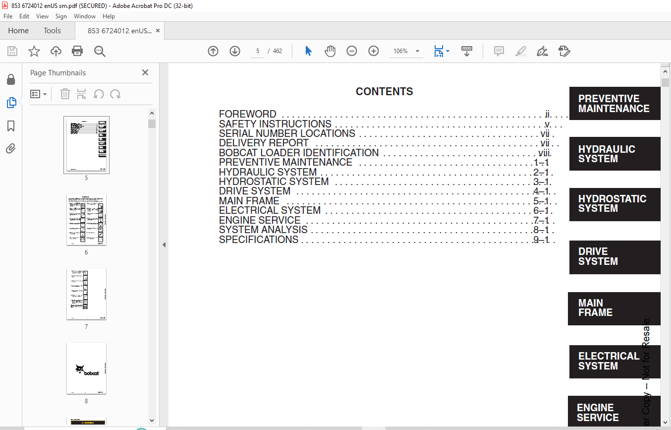
CONTENTS 5
FOREWORD 6
SAFETY INSTRUCTIONS 9
SERIAL NUMBER LOCATIONS 11
LOADER SERIAL NUMBER 11
ENGINE SERIAL NUMBER 11
DELIVERY REPORT 11
BOBCAT LOADER IDENTIFICATION 12
OPTIONS AND ACCESSORIES 13
PREVENTIVE MAINTENANCE 15
SERVICE SCHEDULE 17
LIFTING AND BLOCKING THE LOADER 18
Procedure 18
TRANSPORTING THE LOADER 19
Procedure 19
TOWING THE LOADER 19
Procedure 19
STOPPING THE BOBCAT LOADER 19
LIFTING THE LOADER 20
Four Point Lift 20
Single Point Lift 20
LIFT ARM SUPPORT DEVICE 21
Engaging The Lift Arm Support Device 21
Disengaging The Lift Arm Support Device 21
OPERATOR CAB 22
Description 22
Raising The Operator Cab 22
Lowering The Operator Cab 23
Emergency Exit 23
SEAT BAR RESTRAINT SYSTEM 24
Description 24
Seat Bar Inspection 24
Seat Bar Maintenance 24
AIR CLEANER SERVICE 25
Replacing Filter Element 25
FUEL SYSTEM 27
Fuel Specifications 27
Filling The Fuel Tank 27
Fuel Filter 27
Removing Air From The Fuel System 28
ENGINE LUBRICATION SYSTEM 29
Checking Engine Oil 29
Replacing Oil And Filter 29
ENGINE COOLING SYSTEM 31
Cleaning The Cooling System 31
Checking The Coolant Level 31
Removing Coolant From The Cooling System 32
Propylene Glycol 32
ALTERNATOR BELT 32
Adjusting The Alternator Belt 32
USING A BOOSTER BATTERY (Jump Starting) 33
Procedure 33
HYDRAULIC/HYDROSTATIC SYSTEM 34
Checking And Adding Fluid 34
Replacing Hydraulic/Hydrostatic Filters 34
Replacing Hydraulic Fluid 35
Hydraulic Reservoir Breather Cap 36
SPARK ARRESTOR MUFFLER 37
Cleaning Procedure 37
TIRE MAINTENANCE 38
Wheel Nuts 38
Tire Rotation 38
Tire Mounting 38
FINAL DRIVE TRANSMISSION (CHAINCASE) 39
Checking And Adding Oil 39
Removing Oil From The Chaincase 39
FAN GEARBOX 39
Checking And Maintaining 39
LUBRICATING THE LOADER 40
Procedure 40
REMOTE START SWITCH 42
Procedure 42
HYDRAULIC SYSTEM 45
HYDRAULIC / HYDROSTATIC SCHEMATICS 47
TROUBLESHOOTING 55
HYDRAULIC SYSTEM INFORMATION 56
Flare Connections 56
O–ring Face Seal Connection 56
Straight Thread O–ring Fitting 56
Tubelines And Hoses 56
LIFT CYLINDER(S) 57
Checking The Lift Cylinder 57
Removal And Installation 57
TILT CYLINDER 59
Checking The Tilt Cylinder 59
Removal And Installation 59
Rod End Seal 60
HYDRAULIC CYLINDER 61
Lift Cylinder Identification 61
Tilt Cylinder Identification 62
Disassembly 63
Assembly 65
MAIN RELIEF VALVE 71
Checking The Main Relief Valve 71
Checking The Main Relief Valve Without Auxiliaries 72
Removal And Installation 73
DUAL PRESSURE MAIN RELIEF VALVE – 853H 74
Checking The Low Setting 74
Checking The High Setting 75
Adjusting The Low Setting 77
Adjusting The High Setting 78
SELECT VALVE (G E M Block) 853H 79
Checking The Main Relief Valve 79
HYDRAULIC CONTROL VALVE 80
Removal And Installation 80
Identification Chart 82
Disassembly And Assembly 83
Main Relief Valve 84
Port Relief Valve 84
Anti–Cavitation Valve 85
Rubber Boot 86
Lift Spool And Detent 87
Tilt Spool And Centering Spring 92
Auxiliary Spool 93
Auxiliary Electric Solenoid 94
H Port – Auxiliary Section 95
Base End Restrictor 95
Inspection 95
Spool Seal Installation 96
HYDRAULIC PUMP 97
Checking The Output Of The Pump 97
Removal And Installation 98
Parts Identification 99
Disassembly 100
Inspection 102
Assembly 103
HYDRAULIC PUMP (Double Gear) 853H 105
Checking The Output Of The Pump 105
Removal And Installation 106
Parts Identification 107
Disassembly 108
Inspection 112
Assembly 113
BUCKET POSITION VALVE (Optional) 116
Removal And Installation 116
HYDRAULIC FLUID RESERVOIR 117
Removal And Installation 117
HYDROSTATIC FILTER HOUSING 118
Removal And Installation 118
HYDRAULIC FILTER HOUSING 119
Removal And Installation 119
CONTROL PEDALS 120
Removal And Installation 120
Pedal Adjustment 120
PEDAL INTERLOCK LINKAGE 121
Removal And Installation 121
Pedal Interlock Linkage Adjustment 122
HYDROSTATIC SYSTEM 123
TROUBLESHOOTING 125
HYDROSTATIC SYSTEM INFORMATION 126
Replenishing Valve Function 126
FRONT PANEL 127
Removal And Installation 127
STEERING LEVERS 129
Disassembly And Assembly 129
Pre–Adjustment Checks 131
Adjusting Lever Freeplay 132
Adjusting The Wheel RPM Forward Compared To Reverse Travel 133
Adjusting The Steering Neutral Setting 135
Adjusting The Wheel RPM Left Compared To Right Side 136
HYDROSTATIC MOTOR 137
Removal And Installation 137
Parts Identification 138
Disassembly 139
Inspection 144
Assembly 145
Timing The Hydrostatic Motor 148
HYDROSTATIC PUMP 149
Removal And Installation 149
Replenishing/High Pressure Relief Valve 151
Parts Identification 152
Hydraulic Pump Removal 157
Hydrostatic Pump Separation 157
Charge Pump Disassembly 158
Disassembly 159
Inspection 168
Assembly 170
Charge Pump Assembly 179
Hydrostatic Pump Connection 180
Hydraulic Pump Installation 181
Hydrostatic Pump Neutral Adjustment 182
DRIVE BELT SHIELD 184
Removal And Installation 184
DRIVE BELT 185
Adjusting The Drive Belt 185
Replacing The Drive Belt 186
DRIVE BELT TENSIONER PULLEY 187
Removal And Installation 187
Disassembly 188
Assembly 190
Checking Pulley End Play 194
OIL COOLER 195
Removal And Installation 195
DRIVE SYSTEM 197
PARKING BRAKE PEDAL 199
Removal And Installation 199
Disassembly And Assembly 200
PARKING BRAKE DISC 201
Removal And Installation 201
FRONT CHAINCASE COVER 203
Removal And Installation 203
REAR CHAINCASE COVER 203
Removal And Installation 203
AXLE SEAL 204
Removal And Installation 204
AXLE, SPROCKET AND BEARINGS 206
Removal And Installation 206
REDUCTION GEARCASE 210
Reduction Gearcase Seal 210
Removal And Installation 211
Checking Reduction Gearcase 212
Disassembly 212
Assembly 217
DRIVE CHAIN 221
Removal And Installation 221
CHAINCASE FLUID 222
Removing The Fluid From The Chaincase 222
MAIN FRAME 223
SEAT BAR 225
Removal And Installation 225
Assembly 227
Compressing The Gas Cylinder 228
OPERATOR CAB GAS CYLINDER 229
Removal And Installation 229
Disassembly And Assembly 230
OPERATOR CAB 231
Removal And Installation 231
OPERATOR SEAT 233
Removal And Installation 233
BOB–TACH 234
Removal And Installation 234
Bob–Tach Lever And Wedge 236
Bob–Tach Stops 237
LIFT ARMS 238
Removal And Installation 238
REAR GRILL 239
Removal And Installation 239
REAR DOOR 240
Removal And Installation 240
Hood Removal And Installation 241
Bumper Removal And Installation 241
Door Latch Removal And Installation 241
Door Latch And Catch Adjustment 241
FUEL TANK 242
Removal And Installation 242
Inlet Screen 243
ELECTRICAL SYSTEM 245
ELECTRICAL SCHEMATICS 247
TROUBLESHOOTING 299
ELECTRICAL SYSTEM INFORMATION 300
Description 300
Fuse Location (Standard & BOSS® Option) 300
BATTERY 301
Removal And Installation 301
ALTERNATOR 302
Alternator Output Test 302
Rectifier (Diode) Test 302
Alternator Regulator Test 303
Removal And Installation 304
Disassembly And Inspection 305
Stator Continuity Test 305
Stator Ground Test 305
Rotor Continuity Test 306
Rotor Ground Test 306
Rectifier Continuity (Diode) Test 306
Assembly 307
STARTER 308
Removal And Installation 308
Checking The Starter 309
Parts Identification 310
Disassembly And Assembly 311
Cleaning And Inspection 313
STANDARD INSTRUMENT PANEL 314
Removal And Installation 314
FRONT LIGHTS 315
Removal And Installation 315
RELAY SWITCHES 316
Location 316
ENGINE SERVICE 317
TROUBLESHOOTING 319
ENGINE SPEED CONTROL 320
Removal And Installation 320
Disassembly 320
RADIATOR 321
Removal And Installation 321
COOLANT RECOVERY TANK 323
Removal And Installation 323
ENGINE MUFFLER 324
Removal And Installation 324
AIR CLEANER HOUSING 325
Removal And Installation 325
BLOWER HOUSING/FAN GEARBOX 326
Removal And Installation 326
FAN DRIVE TENSION PULLEY 328
Removal And Installation 328
BLOWER FAN 329
Removal And Installation 329
FAN GEARBOX 330
Parts Identification 330
Disassembly 331
Assembly 336
Checking Backlash 341
ENGINE 344
Removal And Installation 344
Engine Mount Replacement 351
FLYWHEEL 352
Removal And Installation 352
Flywheel Ring Gear 352
BELT SHIELD 353
Removal And Installation 353
VALVE CLEARANCE 354
Adjustment 354
ENGINE COMPRESSION 354
Checking 354
GLOW PLUGS 355
Removal And Installation 355
Checking The Glow Plugs 355
FUEL INJECTION PUMP 356
Description 356
Removal And Installation 356
Timing The Injection Pump 360
FUEL INJECTOR NOZZLES 362
Removal And Installation 362
Checking 363
CYLINDER HEAD 365
Removal And Installation 365
Cylinder Head Surface Alignment 366
Exhaust Manifold 366
VALVES, VALVE SEAT AND GUIDE 367
Removal 367
Installation 367
Reconditioning The Valve And Valve Seats 367
Valve Seat Insert 368
Valve Guide 368
Valve Spring 369
ROCKER ARM AND SHAFT 370
Disassembly And Assembly 370
Checking Rocker Arm And Push Rods 370
PISTON AND CONNECTING ROD 371
Removal 371
Disassembly 371
Checking 372
Assembly 375
Installation 376
CYLINDER LINERS 377
Checking The Cylinder Bore 377
Removal 377
Installation 377
MAIN BEARINGS 378
Description 378
Removal 378
Installation 379
Crankshaft End Play 380
CRANKSHAFT 381
Removal And Installation 381
Checking Tuffriding (Soft Nitriding) Coating 381
Checking the Crankshaft 381
CRANKSHAFT GEAR 383
Removal And Installation 383
TIMING GEARCASE COVER SEAL 384
Removal And Installation 384
TIMING GEARCASE COVER 385
Removal And Installation 385
IDLER GEAR AND HUB 387
Removal 387
Checking 387
Installation 388
FUEL INJECTION PUMP IDLER GEAR 389
Removal And Installation 389
Bearing Installation 389
CAMSHAFT GEAR 390
Removal And Installation 390
TIMING GEARCASE 391
Removal And Installation 391
CAMSHAFT 392
Removal And Installation 392
Checking 392
Camshaft Bearings 393
Tappets 393
Tappet Installation 394
OIL PAN 395
Removal 395
Installation 395
OIL PUMP 396
Removal And Installation 396
Checking 396
Gear Replacement 397
Rotor Replacement 398
Oil Pump Relief Valve 398
Oil Filter Housing And Block 398
WATER PUMP 399
Removal And Installation 399
Disassembly 399
Assembly 400
THERMOSTAT 402
Removal And Installation 402
Checking The Thermostat 402
WATER JACKET TUBE 403
Removal And Installation 403
SYSTEMS ANALYSIS 405
BOBCAT INTERLOCK CONTROL SYSTEM (BICS™) 407
Inspecting The BICS System Controller (Engine STOPPED – Key ON) 407
Inspecting The Seat And Seat Bar Sensors (Engine RUNNING) 407
Inspecting The Traction Lock (Engine RUNNING) 407
Inspecting The Lift Arm By–Pass Control 407
Maintenance 407
Troubleshooting Chart 408
Troubleshooting Guide 409
BICS SYSTEM CONTROLLER 409
TRACTION LOCK 410
SEAT SENSOR 411
SEAT BAR SENSOR 412
LIFT LOCK BY–PASS VALVE 413
BICS™ SYSTEM CONTROLLER 414
Removal And Installation 414
Controller Test 415
SEAT BAR SENSOR 416
Removal And Installation 416
Seat Bar Sensor Test 417
SEAT SENSOR 418
Removal And Installation 418
Seat Sensor Test 419
TRACTION LOCK 420
Removal And Installation 420
LIFT LOCK BY–PASS VALVE 421
Removal And Installation 421
Disassembly And Assembly 422
TILT LOCK VALVE 423
Removal And Installation 423
Disassembly And Assembly 424
BOSS® DIAGNOSTIC TOOL 425
Procedure 425
SENDER AND SENSOR 425
Service Checks 425
Component 425
RPM SENSOR 425
Adjustment 425
MONITOR SERVICE CODES 426
TROUBLESHOOTING THE BOSS® & LCD DISPLAY 429
OPERATION SENSING SYSTEM UNIT 430
Removal And Installation 430
BOSS® INSTRUMENT PANEL 431
Removal And Installation 431
PWM MODULE 432
Description 432
PWM TROUBLESHOOTING 433
Conditions 433
Chart 434
PWM CONTROL HANDLE 435
Handle Testing 435
PWM ELECTRIC SOLENOID 435
Solenoid Coil Testing 435
ELECTRICAL/HYDRAULIC CONTROLS REFERENCE 436
Controls Identification Chart 436
SPECIFICATIONS 437
LOADER SPECIFICATIONS 439
LOADER DIMENSIONS 439
OPERATION & PERFORMANCE 439
ENGINE 439
HYDRAULIC SYSTEM 440
ELECTRICAL 440
DRIVE SYSTEM 440
CAPACITIES 440
TIRES 440
VIBRATION DATA 440
ENGINE SPECIFICATIONS 441
Cylinder Head 441
Valve, Valve Guide & Seat Insert 441
Valve Springs 441
Rocker Arm 441
Tappets 441
Piston, Pin & Rings 442
Connecting Rod & Bearing 442
Cylinder Liners 442
Camshaft 442
Crankshaft 443
Idler Gear 443
Oil Pump 443
Fuel System 443
Torque For General Metric Bolts 444
TORQUE SPECIFICATIONS FOR LOADER 445
HYDRAULIC/HYDROSTATIC FLUID SPECIFICATIONS 447
STANDARD TORQUE SPECIFICATIONS FOR BOLTS 448
DECIMAL AND MILLIMETER EQUIVALENTS 449
U S TO METRIC CONVERSION 449
SERVICE MANUAL REVISIONS 451
850–001 451
850–002 453
850–003 455
850–004 457
850–005 459
850-006 461
DESCRIPTION:
Bobcat 853 & 853H Loader Service Manual 6724012 (6-12) – PDF DOWNLOAD
FOREWORD:
This manual is for the Bobcat loader mechanic. It provides necessary servicing and adjustment procedures for the Bobcat loader and its component parts and systems. Refer to the Operation & Maintenance Manual for operating instructions, starting procedure, daily checks, etc.
SAFETY INSTRUCTIONS:
The following publications provide information on the safe use and maintenance of the loader and attachments:
• The Delivery Report is used to assure that complete instructions have been given to the new owner and that the machine
is in safe operating condition.
• The Operation & Maintenance Manual delivered with the loader gives operating information as well as routin e
maintenance and service procedures. It is a part of the loader and must stay with the machine when it is sold. Replacement
Operation & Maintenance Manuals can be ordered from your Bobcat loader dealer.
• The loader has machine signs (decals) which instruct on the safe operation and care. The signs and their locations are
shown in the Operation & Maintenance Manual. Replacement signs are available from your Bobcat loader dealer.
• The loader has a plastic Operator’s Handbook fastened to the operator cab. Its brief instructions are convenient to the
operator. The handbook is available from your dealer in English edition or French, German, Italian, Dutch, Spanish,
Portuguese, Finnish, Danish & Swedish editions.
• The EMI Safety Manual (available in Spanish) delivered with the loader gives general safety information.
• The Service Manual and Parts Manual are available from your dealer for use by mechanics to do shop–type service and
repair work.
• The Skid–Steer Loader Operator Training Course is available through your local Bobcat dealer. This course is intended
to provide rules and practices for correct operation of the Bobcat loader. The course is available in English and Spanish
versions.
• The Bobcat Skid–Steer Loader Safety Video is available from your Bobcat Dealer.
VIDEO PREVIEW OF THE MANUAL:
IMAGES PREVIEW OF THE MANUAL:

PLEASE NOTE:
- This is not a physical manual but a digital manual – meaning no physical copy will be couriered to you. The manual can be yours in the next 2 mins as once you make the payment, you will be directed to the download page IMMEDIATELY.
- This is the same manual used by the dealers inorder to diagnose your vehicle of its faults.
- Require some other service manual or have any queries: please WRITE to us at [email protected]
S.V