

Bobcat 763 & 763 High Flow Loader Service Manual 6900091 (6-12) – PDF DOWNLOAD
FILE DETAILS:
Bobcat 763 & 763 High Flow Loader Service Manual 6900091 (6-12) – PDF DOWNLOAD
Language : English
Pages : 584
Downloadable : Yes
File Type : PDF
TABLE OF CONTENTS:
Bobcat 763 & 763 High Flow Loader Service Manual 6900091 (6-12) – PDF DOWNLOAD
MAINTENANCE SAFETY 3
ALPHABETICAL INDEX 5
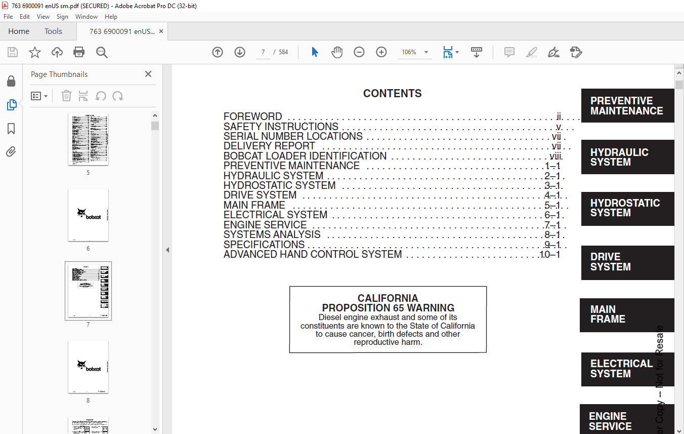
CONTENTS 7
FOREWORD 9
SAFETY INSTRUCTIONS 11
FIRE PREVENTION 12
SERIAL NUMBER LOCATIONS 13
LOADER SERIAL NUMBER 13
ENGINE SERIAL NUMBER 13
DELIVERY REPORT 13
BOBCAT LOADER IDENTIFICATION 14
PREVENTIVE MAINTENANCE 15
SERVICE SCHEDULE 17
LIFTING AND BLOCKING THE LOADER 18
Procedure 18
TRANSPORTING THE BOBCAT LOADER 19
TOWING THE LOADER 19
STOPPING THE BOBCAT LOADER 19
LIFTING THE LOADER 20
Single Point Lift 20
LIFT ARM SUPPORT DEVICE 21
Engaging The Lift Arm Support Device 21
Disengaging The Lift Arm Support Device 22
OPERATOR CAB 23
Description 23
Emergency Exit 23
Raising The Operator Cab 24
Lowering The Operator Cab 25
SEAT BAR RESTRAINT SYSTEM (Foot Pedals) 26
Description 26
Seat Bar Inspection 26
Seat Bar Maintenance 26
SEAT BAR RESTRAINT SYSTEM (Mechanical Hand Controls) 27
Description 27
Seat Bar Inspection 27
Seat Bar Maintenance 27
SEAT BAR RESTRAINT SYSTEM (Advanced Hand Controls) 28
Description 28
Seat Bar Inspection 28
Seat Bar Maintenance 28
AIR CLEANER SERVICE 29
Replacing Filter Element 29
FUEL SYSTEM 31
Fuel Specifications 31
Filling The Fuel Tank 31
Fuel Filter 31
Removing Air From The Fuel System 32
ENGINE LUBRICATION SYSTEM 33
Checking Engine Oil 33
Oil Chart 33
Replacing Oil And Filter 33
ENGINE COOLING SYSTEM 35
Cleaning The Cooling System 35
Checking The Coolant Level 35
Replacing The Coolant 36
ALTERNATOR BELT 37
Adjusting The Alternator Belt 37
FAN GEARBOX 37
Checking And Maintaining 37
HYDRAULIC/HYDROSTATIC SYSTEM 38
Checking And Adding Fluid 38
Replacing Hydraulic/Hydrostatic Filter 38
Replacing Hydraulic Fluid 39
Hydraulic Reservoir Breather Cap 40
SPARK ARRESTOR MUFFLER 41
Cleaning Procedure 41
TIRE MAINTENANCE 42
Wheel Nuts 42
Tire Rotation 42
Tire Mounting 42
FINAL DRIVE TRANSMISSION (CHAINCASE) 43
Checking And Adding Oil 43
Replacing Oil In The Chaincase 43
DRIVE BELT 44
Adjusting The Drive Belt Equipped With The Spring Loaded Drive Idler 44
Adjusting The Drive Belt Equipped With The Fixed Drive Idler 46
Drive Belt Replacement 47
LUBRICATION OF THE BOBCAT LOADER 48
Procedure 48
BOB–TACH 50
Inspection And Maintenance 50
REMOTE START SWITCH 51
Procedure 51
HYDRAULIC SYSTEM 53
HYDRAULIC/HYDROSTATIC SCHEMATICS 57
TROUBLESHOOTING 85
HYDRAULIC SYSTEM INFORMATION 86
Tightening Procedure 86
LIFT CYLINDER(S) 87
Checking The Lift Cylinder(s) For Internal Leakage 87
Removal And Installation 87
TILT CYLINDER 88
Checking The Tilt Cylinder For Internal Leakage 88
Removal And Installation 88
Rod End Seal Replacement 89
HYDRAULIC CYLINDER IDENTIFICATION 90
Lift Cylinder Components 90
Tilt Cylinder Components 91
HYDRAULIC CYLINDERS 92
Disassembly 92
Assembly 94
BICS™ VALVE (S/N 512220298 & Above, 512440721 & Above and 512612258 & Above) 100
Removal 100
Lift Arm By–Pass Orifice Disassembly 101
Check Valve Disassembly 101
Lock Valve Disassembly 102
BICS™ Valve Solenoid Disassembly 103
BICS™ Valve Solenoid Assembly 104
Lock Valve Assembly 105
Check Valve Assembly 105
Lift Arm By–Pass Orifice Assembly 106
Installation 107
CONTROL VALVE (S/N 512220298 & Above, 512440721 & Above and 512612258 & Above) 108
Removal And Installation 108
Identification Chart 111
Disassembly 112
Lift Base End Restrictor Disassembly 112
Load Check Valve Disassembly 112
Main Relief Valve Disassembly 113
Port Relief Valve Disassembly 114
Anti–Cavitation Valve Disassembly 115
Rubber Boot Disassembly 116
Lift Spool And Detent Disassembly 117
Tilt Spool And Centering Spring Disassembly 120
Auxiliary Spool Disassembly 122
Auxiliary Electric Solenoid Disassembly 123
Port–Auxiliary Section Disassembly 124
Cleaning And Inspection 124
Port–Auxiliary Section Assembly 125
Auxiliary Electric Solenoid Assembly 125
Auxiliary Spool Assembly 126
Tilt Spool And Centering Spring Assembly 127
Lift Spool And Detent Assembly 129
Rubber Boot Assembly 131
Anti–Cavitation Valve Assembly 132
Port Relief Valve Assembly 133
Main Relief Valve Assembly 134
Load Check Valve Assembly 134
Spool Seal Installation 136
CONTROL VALVE (S/N 512220297 & Below,512440720 & Below and 512612257 & Below) 137
Removal And Installation 137
Identification Chart 140
Disassembly And Assembly 141
Load Check Valve 141
Main Relief Valve 142
Port Relief Valve 142
Anti–Cavitation Valve 143
Rubber Boot 144
Lift Spool Detent 145
Tilt Centering Spring 149
Auxiliary Spool 150
Auxiliary Electric Solenoid 151
Plug/Port Relief Valve 152
Inspection 152
Identification And Installation Of Spool Seal 153
MAIN RELIEF VALVE 154
Checking 154
Adjustment 155
Removal And Installation 155
HYDRAULIC PUMP 156
Removal And Installation 156
Checking The Output Of The Hydraulic Pump 158
Checking The Output Of The High Flow Hydraulic Pump (763H) 160
Disassembly And Assembly 161
Inspection 163
Identification 163
Removal And Installation (763H) 164
Identification (763H) 167
Disassembly And Assembly (763H) 168
HYDRAULIC FILTER HOUSING 171
Removal And Installation 171
HYDRAULIC FLUID RESERVOIR 172
Removal And Installation 172
CONTROL PEDALS 173
Removal And Installation 173
Pedal Adjustment 173
SELECT VALVE (763H) 174
Checking the Main Relief Valve in High Horsepower Select Valve 174
Removal And Installation 175
Disassembly And Assembly (New Style Valve) 177
Solenoid Testing (New Style Valve) 178
Disassembly And Assembly (Old Style Valve) 179
Solenoid Testing (Old Style Valve) 180
PEDAL INTERLOCK LINKAGE 181
Removal And Installation 181
Adjustment 182
LIFT LOCK BY–PASS VALVE 183
Removal And Installation (S/N 512220298 & Above, S/N 512440721 & Above, S/N 512612258 & Above) 183
Removal And Installation (S/N 512220297 & Below, S/N 512440720 & Below, S/N 512612257 & Below) 185
Disassembly And Assembly (S/N 512220297 & Below, S/N 512440720 & Below, S/N 512612257 & Below) 186
TILT LOCK VALVE 187
Removal And Installation (S/N 512220297 & Below, S/N 512440720 & Below, S/N 512612257 & Below) 187
Disassembly And Assembly (S/N 512220297 & Below, S/N 512440720 & Below, S/N 512612257 & Below) 189
HYDROSTATIC SYSTEM 191
TROUBLESHOOTING 193
HYDROSTATIC SYSTEM INFORMATION 194
Replenishing Valve Function 194
Checking Charge Pressure 194
CONTROL PANEL 195
Removal And Installation 195
Steering Shock Removal And Installation 196
Steering Shaft Removal And Installation 196
Steering Shaft Disassembly And Assembly 196
Steering Lever Removal And Installation 197
Rubber Boot Replacement 197
STEERING LINKAGE 198
Removal And Installation 198
Steering Linkage Adjustment 200
Steering Neutral Adjustment 202
HYDROSTATIC DRIVE MOTOR 204
Removal And Installation 204
Identification (S/N 512218843 & Below, S/N 512612191 & Below & S/N 512440645 & Below) 205
Disassembly And Assembly (S/N 512218843 & Below, S/N 512612191 & Below & S/N 512440645 & Below) 206
nspection (S/N 512218843 & Below, S/N 512612191 & Below & S/N 512440645 & Below) 211
Timing The Hydrostatic Motor (S/N 512218843 & Below, S/N 512612191 & Below & S/N 512440645 & Below) 212
HYDROSTATIC MOTOR 30 SERIES 213
Identification (S/N 512218844 & Above, S/N 512612192 & Above, & S/N 512440646 & Above) 213
Disassembly (S/N 512218844 & Above, S/N 512612192 & Above, & S/N 512440646 & Above) 214
Assembly (S/N 512218844 & Above, S/N 512612192 & Above, & S/N 512440646 & Above) 219
HYDROSTATIC PUMP 225
Removal And Installation 225
Identification MODEL: 763 228
Disassembly And Assembly 230
Inspection 238
Swashplate Pre–Load 240
DRIVE BELT HOUSING 241
Removal And Installation 241
SPRING LOADED DRIVE BELT TENSIONER PULLEY 243
Removal And Installation 243
Identification 244
Disassembly 245
Assembly 246
FIXED DRIVE BELT TENSIONER PULLEY 248
Removal And Installation 248
Identification 249
Disassembly 250
Assembly 252
Checking Pulley End Play 256
OIL COOLER 256
Removal And Installation 256
DRIVE SYSTEM 257
PARKING BRAKE 259
Removal And Installation 259
Disassembly And Assembly 259
PARKING BRAKE DISC 260
Removal And Installation 260
TRACTION LOCK GUIDES 261
Disassembly 261
Assembly 262
CHAINCASE FLUID 264
Removing Oil From The Chaincase 264
CHAINCASE COVERS 265
Center Chaincase Cover Removal And Installation 265
Front Chaincase Cover Removal And Installation 266
Rear Chaincase Cover Removal And Installation 266
MOTOR CARRIER 267
Shaft Seal Replacement 267
Removal And Installation 269
Disassembly 270
Assembly 271
AXLE SEAL 275
Removal And Installation 275
AXLE, SPROCKET AND BEARINGS 277
Removal And Installation 277
DRIVE CHAIN 281
Removal 281
MAIN FRAME 283
SEAT BAR (W/GAS CYLINDER) 285
Removal And Installation 285
Assembly 287
Compressing the Gas Cylinder 288
SEAT BAR (W/COMPRESSION SPRING) 289
Removal And Installation 289
Assembling Components 292
Compression Spring Disassembly And Assembly 292
OPERATOR CAB GAS CYLINDER 293
Removal And Installation 293
Disassembly And Assembly 293
OPERATOR CAB 294
Removal And Installation 294
OPERATOR SEAT 297
Removal And Installation 297
BOB–TACH 298
Removal And Installation 298
Bob–Tach Lever And Wedge 300
Bob–Tach Stops 301
LIFT ARMS 302
Removal And Installation 302
REAR GRILL 306
Removal And Installation 306
FUEL TANK 307
Removal And Installation 307
Fuel Level Sender 308
REAR DOOR 309
Removal And Installation (2 piece door) 309
Removal And Installation (One Piece Door) 310
Hood Removal And Installation (Two Piece Door) 311
Door Latch Removal And Installation 311
Door Latch And Catch Adjustment 312
REAR LIGHTS 313
Removal and Installation (One Piece Door) 313
ELECTRICAL SYSTEM 315
ELECTRICAL SCHEMATICS 321
TROUBLESHOOTING 347
ELECTRICAL SYSTEM INFORMATION 348
Description 348
Fuse Location (Standard & BOSS® Option) 348
BATTERY 349
Removal And Installation 349
Servicing The Battery 350
Using A Booster Battery (Jump Starting) 351
ALTERNATOR 352
Alternator Output Test 352
Rectifier (Diode) Test 353
Alternator Regulator Test 353
Removal And Installation 354
Adjusting The Alternator Belt 354
Disassembly And Inspection 355
Stator Continuity Test 355
Stator Ground Test 355
Rotor Continuity Test 356
Rotor Ground Test 356
Rectifier Continuity (Diode) Test 356
Assembly 357
STARTER (DELCO REMY) 358
Removal And Installation 358
Checking The Starter 358
Parts Identification 359
Disassembly And Assembly 360
Cleaning And Inspection 362
STARTER (DENSO) 363
Parts Identification 363
Disassembly 364
Inspection And Repair 369
No Load Test 372
Assembly 372
STANDARD INSTRUMENT PANEL 379
Removal And Installation 379
FRONT LIGHTS 380
Removal And Installation 380
RELAY SWITCHES 381
Location 381
ENGINE SERVICE 383
TROUBLESHOOTING 385
ENGINE SPEED CONTROL 386
Removal And Installation 386
Disassembly 386
RADIATOR 387
Removal And Installation 387
ENGINE MUFFLER 388
Removal And Installation 388
BLOWER HOUSING/FAN GEARBOX 389
Removal And Installation 389
Tension Pulley Removal And Installation 392
Blower Fan Disassembly And Assembly 393
FAN GEARBOX 395
Identification 395
Disassembly 396
Assembly 401
Checking Backlash 406
AIR CLEANER 409
Removal And Installation 409
ENGINE 410
Removal And Installation 410
Engine Mount Replacement 415
FLYWHEEL 416
Removal And Installation 416
Flywheel Ring Gear 416
ENGINE COMPRESSION 417
Checking 417
GLOW PLUGS 418
Checking The Glow Plugs 418
Removal And Installation 419
FUEL INJECTION PUMP 420
Checking The Injection Pump 420
Adjusting Shut–Off Linkage 420
Removal And Installation 421
Timing The Injection Pump 424
FUEL INJECTION NOZZLES 425
Removal And Installation 425
Checking The Injector Nozzle 427
CYLINDER HEAD 428
Removal And Installation 428
Disassembly And Assembly 429
Servicing The Cylinder Head 430
Top Clearance 430
VALVE, VALVE SEAT AND GUIDE 431
Checking The Valve Guide 431
Reconditioning The Valve And Valve Seat 432
Valve Spring 433
VALVE CLEARANCE 434
Adjustment 434
ROCKER ARM AND SHAFT 434
Checking 434
TIMING GEARCASE COVER 435
Removal And Installation 435
IDLER GEAR AND CAMSHAFT 437
Removal And Installation 437
Servicing The Camshaft 438
Servicing The Idler Gear And Shaft 439
TIMING GEARS 440
Checking Backlash 440
FUEL CAMSHAFT 441
Removal And Installation 441
Governor 441
CRANKSHAFT GEAR 442
Removal And Installation 442
OIL PUMP 442
Removal And Installation 442
Oil Pump Service 442
Checking Engine Oil Pressure 443
Relief Valve 443
PISTON AND CONNECTING ROD 444
Removal And Installation 444
Servicing The Piston And Connecting Rod 445
Connecting Rod Alignment 447
CRANKSHAFT AND BEARINGS 448
Removal And Installation 448
Servicing The Crankshaft And Bearings 449
CYLINDER BORE 453
Checking The Cylinder Bore 453
WATER PUMP 454
Disassembly and Assembly 454
SYSTEMS ANALYSIS 455
BOBCAT INTERLOCK CONTROL SYSTEM (BICS™) (S/N 512235900 & Above), (S/N 512442000 & Above), (S/N 512613600 & Above) 457
Inspecting The BICS™ Controller 457
Inspecting Deactivation Of The Auxiliary Hydraulics System (Engine STOPPED – Key ON) 457
Inspecting The Seat Bar Sensor (Engine RUNNING) 457
Inspecting The Traction Lock (Engine RUNNING) 457
Inspecting The Lift Arm By–Pass Control 457
Additional Inspection For Loaders With Advanced Hand Controls 457
Troubleshooting Chart 458
BOBCAT INTERLOCK CONTROL SYSTEM (BICS™) (S/N 512235899 & Below ), (S/N 512441999 & Below), (S/N 512613599 & Below) 459
Inspecting The BICS™ Controller 459
Inspecting Deactivation Of The Auxiliary Hydraulics System (Engine STOPPED – Key ON) 459
Inspecting The Seat And Seat Bar Sensors (Engine Running) 459
Inspecting The Traction Lock (Engine Running) 459
Inspecting The Lift Arm By–Pass Control 459
Maintenance 460
Troubleshooting Chart 461
BOBCAT INTERLOCK CONTROL SYSTEM (BICS™) 462
Troubleshooting Guide 462
BICS CONTROLLER 462
TRACTION LOCK 463
SEAT SENSOR 464
SEAT BAR SENSOR 465
SEAT SENSOR 466
Seat Sensor Test 466
Removal And Installation 467
BICS™ Controller Seat Sensor Circuit Test 468
BICS™ SYSTEM CONTROLLER 469
Removal And Installation 469
SEAT BAR SENSOR 470
Seat Bar Sensor Test 470
Removal And Installation 471
BICS™ Controller Seat Bar Sensor Circuit Test 472
TRACTION LOCK 473
Removal And Installation 473
BOSS® DIAGNOSTIC TOOL 475
Procedure 475
SENDER AND SENSOR 475
Service Checks 475
RPM SENSOR 475
Adjustment 475
MONITOR SERVICE CODES 476
TROUBLESHOOTING THE BOSS® & LCD DISPLAY 479
OPERATION SENSING SYSTEM UNIT 480
Removal And Installation 480
BOSS® INSTRUMENT PANEL 481
Removal And Installation 481
ELECTRICAL/HYDRAULIC CONTROLS REFERENCE 482
Controls Identification Chart 482
SPECIFICATIONS 483
SKID STEER LOADER SPECIFICATIONS 485
PERFORMANCE 485
CONTROLS 485
ENGINE 485
HYDRAULIC SYSTEM 486
ELECTRICAL 486
DRIVE SYSTEM 486
CAPACITIES 486
TIRES 486
ENGINE SPECIFICATIONS 487
Fuel Injection Nozzles 487
Fuel Injection Pump 487
Cylinder Head 487
Valves 487
Valve Springs 487
Valve Timing 487
Rocker Arms 487
Camshaft 488
Tappet 488
Cylinders 488
Piston Rings 488
Pistons 488
Connecting Rod 488
Oil Pump 488
Crankshaft 489
Crankshaft 489
Thermostat 489
Crankshaft Re–Grind Data 490
Torque For General Metric Bolts 491
HYDRAULIC CONNECTION SPECIFICATIONS 492
O–ring Face Seal Connection 492
Straight Thread O–ring Fitting 492
Tubelines And Hoses 492
Flare Fitting 492
O–ring Flare Fitting 493
Port Seal Fitting 495
HYDRAULIC/HYDROSTATIC FLUID SPECIFICATIONS 496
TORQUE SPECIFICATIONS FOR LOADER 497
STANDARD TORQUE SPECIFICATIONS FOR BOLTS 498
DECIMAL AND MILLIMETER EQUIVALENTS 499
U S TO METRIC CONVERSION 499
ADVANCE HAND CONTROL SYSTEM (AHC) 501
ADVANVED HANDCONTROL ELECTRICAL SCHEMATICS 503
AHC COMPONENTS 513
Identification 513
TROUBLESHOOTING (AHC) 514
ACTUATOR VOLTAGE TEST 516
Procedure 516
HANDLE CONTROL UNIT TEST 519
Procedure 519
BOBCAT INTERLOCK CONTROL SYSTEM (BICS™) 522
ADVANCED HAND CONTROLS (AHC) 522
AHC/PWM CONTROLLER 523
Removal And Installation 523
Test 523
Description 524
Conditions 525
Troubleshooting Chart 525
Handle Testing 526
Solenoid Coil Testing 526
CONTROL HANDLE (ADVANCED HAND CONTROL) (AHC) 527
Control Handle Unit Removal And Installation 527
Control Unit Connector 530
Switch Handle Removal And Installation 531
AHC Handle Removal And Installation 534
AHC Handle Disassembly And Assembly 535
AHC Steering Lever Removal And Installation 536
AHC Steering Lever Boot 536
Actuators Removal And Installation 537
Actuators Disassembly And Assembly 538
CONTROL HANDLE (ADVANCED HAND CONTROL) (AHC) (W/PUSH BUTTON FLOAT) 539
Components Identification 539
Controller Connector And Wire Identification 540
AHC/PWM Controller Removal And Installation 541
Handle Sensor Removal And Installation 542
Handle Sensor Connector 544
Switch Handle Removal And Installation 545
Control Handle Removal And Installation 548
Control Handle Disassembly And Assembly 549
Control Lever Removal And Installation 550
Control Lever Boot 551
Actuators Disassembly And Assembly 552
BICS™ VALVE 553
Lift Arm By–Pass Orifice 553
Check Valve 554
Lock Valve 554
BICS™ Valve Solenoid 555
Removal And Installation 556
HYDRAULIC CONTROL VALVE 557
Removal And Installation 557
Identification Chart 559
Disassembly And Assembly 560
Load Check Valve 560
Lift Base End Restrictor 560
Main Relief Valve 561
Port Relief Valve (Lift) 562
Anti–Cavitation/Port Relief Valve 562
Port Relief Valve (Tilt) 563
Anti–Cavitation Valve 563
Rubber Boot 564
Lift And Tilt Spool 565
Inspection 567
Auxiliary Spool 568
Auxiliary Electrical Solenoid 569
Spool Seal Installation 570
H–Port Auxiliary Section 571
SERVICE MANUAL REVISIONS 573
763, 763H–1 573
763, 763H–2 575
763, 763H–3 577
763, 763H–4 579
763, 763H-5 581
763, 763H-6 583
DESCRIPTION:
Bobcat 763 & 763 High Flow Loader Service Manual 6900091 (6-12) – PDF DOWNLOAD
S/N 512212001 thru 512249999
S/N 512440001 thru 512449999
S/N 512612001 thru 512619999
FOREWORD:
This manual is for the Bobcat loader mechanic. It provides necessary servicing and adjustment procedures for the Bobcat loader and its component parts and systems. Refer to the Operation & Maintenance Manual for operating instructions, starting procedure, daily checks, etc.
SAFETY INSTRUCTIONS:
The following publications provide information on the safe use and maintenance of the loader and attachments:
• The Delivery Report is used to assure that complete instructions have been given to the new owner and that the machine
is in safe operating condition.
• The Operation & Maintenance Manual delivered with the loader gives operating information as well as routine maintenance
and service procedures. It is a part of the loader and must stay with the machine when it is sold. Replacement Operation
& Maintenance Manuals can be ordered from your Bobcat loader dealer.
• The loader has machine signs (decals) which instruct on the safe operation and care. The signs and their locations are
shown in the Operation & Maintenance Manual. Replacement signs are available from your Bobcat loader dealer.
• The loader has a plastic Operator’s Handbook fastened to the operator cab. Its brief instructions are convenient to the
operator. The Handbook is available from your dealer in an English edition or one of many other languages. See your Bobcat
dealer for more information on translated versions.
• The EMI Safety Manual (available in Spanish) delivered with the loader gives general safety information.
• The Service Manual and Parts Manual are available from your dealer for use by mechanics to do shop–type service and
repair work.
• The Skid–Steer Loader Operator Training Course is available through your local dealer. This course is intended to provide
rules and practices for correct operation of the Bobcat loader. The course is available in English and Spanish version.
• The Service Safety Training Course is available from your Bobcat dealer. This course provides information for safe and
correct service procedures for Bobcat Skid–Steer loaders.
• The Bobcat Skid–Steer Loader Safety Video is available from your Bobcat Dealer.
VIDEO PREVIEW OF THE MANUAL:
IMAGES PREVIEW OF THE MANUAL:


PLEASE NOTE:
- This is the SAME exact manual used by your dealers to fix your vehicle.
- The same can be yours in the next 2-3 mins as you will be directed to the download page immediately after paying for the manual.
- Any queries / doubts regarding your purchase, please feel free to contact [email protected]
S.V


