

Bobcat 753 Loader G Series Service Manual 6900976 (10-12) – PDF DOWNLOAD
FILE DETAILS:
Bobcat 753 Loader G Series Service Manual 6900976 (10-12) – PDF DOWNLOAD
Language : English
Pages : 726
Downloadable : Yes
File Type : PDF
TABLE OF CONTENTS:
Bobcat 753 Loader G Series Service Manual 6900976 (10-12) – PDF DOWNLOAD
MAINTENANCE SAFETY 3
ALPHABETICAL INDEX 5
CONTENTS 7
FOREWORD 8
SAFETY INSTRUCTIONS 11
Fire Prevention 13
SERIAL NUMBER LOCATIONS 15
Loader Serial Number 15
Engine Serial Number 15
DELIVERY REPORT 15
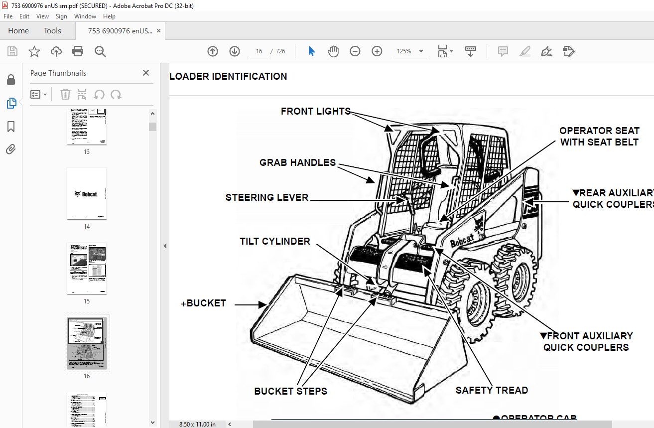
LOADER IDENTIFICATION 16
SAFETY AND MAINTENANCE 17
LIFTING AND BLOCKING THE LOADER 19
Procedure 19
LIFT ARM SUPPORT DEVICE 21
Installing Lift Arm Support Device 21
Removing The Lift Arm Support Device 22
OPERATOR CAB 23
Description 23
Raising The Operator Cab 23
Lowering The Operator Cab 24
Emergency Exit 25
TRANSPORTING THE BOBCAT LOADER 27
Procedure 27
TOWING THE LOADER 29
Procedure 29
REMOTE START 31
Procedure 31
SERVICE SCHEDULE 35
Chart 35
AIR CLEANER SERVICE 37
Checking 37
Replacing Filter Element(s) 38
ENGINE COOLING SYSTEM 41
Cleaning The Cooling System 41
Checking The Coolant Level 41
Replacing The Coolant 42
FUEL SYSTEM 45
Fuel Specifications 45
Filling the Fuel Tank 45
Fuel Filter 46
Removing Air From The Fuel System 47
ENGINE LUBRICATION SYSTEM 49
Checking Engine Oil 49
Oil Chart 49
Replacing Oil And Filter 49
HYDRAULIC/HYDROSTATIC SYSTEM 51
Checking And Adding Fluid 51
Replacing Hydraulic/Hydrostatic Filter 51
Replacing Hydrostatic Motor Case Drain Filter(s) 52
Replacing Hydraulic Fluid 53
Breather Cap 54
FINAL DRIVE TRANSMISSION (CHAINCASE) 55
Checking And Adding Oil 55
Removing The Oil 55
FAN GEARBOX 57
Checking And Maintaining 57
BOB-TACH 59
Inspection And Maintenance 59
POWER BOB-TACH 61
Inspection And Maintenance 61
LUBRICATION OF THE BOBCAT LOADER 63
Procedure 63
TIRE MAINTENANCE 67
Wheel Nuts 67
Rotating 67
Mounting 67
SPARK ARRESTOR MUFFLER 69
Servicing 69
HYDRAULIC SYSTEM 71
HYDRAULIC/HYDROSTATIC SCHEMATICS 75
HYDRAULIC SYSTEM INFORMATION 79
Glossary Of Hydraulic/Hydrostatic Symbols 79
Tighten Procedures 83
Troubleshooting Chart 84
CYLINDER (LIFT) 85
Checking 85
Removal And Installation 86
Identification 87
Disassembly 88
Assembly 89
CYLINDER (TILT) 93
Checking 93
Removal And Installation 93
Rod End Pivot Pin Bushing And Seal Replacement 95
Identification 96
Disassembly 97
Assembly 98
CYLINDER (POWER BOB-TACH) 101
Checking 101
Removal And Installation 102
Parts Identification 103
Disassembly 104
Assembly 105
MAIN RELIEF VALVE 109
Checking 109
Adjustment 110
Removal and Installation 111
HYDRAULIC CONTROL VALVE (FOOT CONTROL) 113
Removal And Installation (S/N 515840211 & Below) 113
Removal And Installation (S/N 515840212 & Above) 117
BICS™ Valve Removal And Installation 122
BICS™ Valve Lift Arm By-Pass Orifice Disassembly And Assembly 123
BICS™ Valve Check Valve Disassembly And Assembly 124
BICS™ Valve Lock Valve Disassembly And Assembly 125
BICS™ Valve Solenoid Disassembly And Assembly 126
BICS™ Valve Solenoid Testing 127
Identification Chart 128
Lift Base End Restrictor 129
Load Check Valves 129
Main Relief Valve 130
Port Relief Valve 131
Anti-Cavitation Valve 131
Plug 132
Rubber Boot 133
Lift And Tilt Lock Block Removal And Installation 134
Lift Spool and Detent 135
Tilt Spool Removal And Installation 144
Auxiliary Spool Removal And Installation 146
Auxiliary Electric Solenoid Disassembly 146
Port-Auxiliary Section Disassembly 147
Cleaning And Inspection 148
HYDRAULIC CONTROL VALVE (ADVANCED CONTROL SYSTEM) (ACS) 149
Description 149
Removal And Installation (S/N 515840211 & Below) 149
Removal And Installation (S/N 515840212 & Above) 152
Actuator Removal And Installation 156
BICS™ Valve, Removal And Installation 157
BICS™ Valve, Lift Arm By-Pass Orifice Removal and Installation 158
BICS™ Valve, Check Valve Removal and Installation 159
BICS™ Valve, Lock Valve Removal and Installation 160
BICS™ Valve, Solenoid Removal and Installation 161
BICS™ Valve, Solenoid Testing 162
Identification Chart (AHC) 163
Identification Chart (ACS) 164
Lift Base End Restrictor 165
Load Check Valve 165
Main Relief Valve 166
Port Relief Valve 167
Anti-Cavitation Valve/Port Relief Valve 168
Anti-Cavitation Valve 169
Lift Spool Removal And Installation 170
Tilt Spool Removal And Installation 171
Lift And Tilt Spool Disassembly And Assembly 172
Auxiliary Spool Removal And Installation 173
Auxiliary Electric Solenoid 174
Port-Auxiliary Section 175
Cleaning And Inspection 175
LIFT ARM BY-PASS CONTROL VALVE 177
Inspecting 177
Removal And Installation 177
Disassembly And Assembly 178
HYDRAULIC PUMP (ALUMINUM) 179
Checking The Output Of The Hydraulic Pump 179
Removal And Installation 180
Parts Identification 182
Disassembly And Assembly 183
Inspection 185
HYDRAULIC PUMP (CAST IRON) 187
Check The Output Of The Hydraulic Pump Without Power Bob-Tach 187
Check The Output Of The Hydraulic Pump With Power Bob-Tach 189
Removal And Installation 191
Identification 195
Disassembly And Assembly 196
HYDRAULIC/HYDROSTATIC FILTER 201
Housing Removal And Installation 201
HYDRAULIC FLUID RESERVOIR 203
Removal And Installation 203
BUCKET POSITION VALVE 205
Solenoid Removal And Installation 205
Solenoid Testing 205
Removal And Installation 206
Disassembly And Assembly 207
REAR AUXILIARY DIVERTER VALVE (SINGLE SHUTTLE) 211
Removal And Installation 211
Disassembly 213
Inspection 214
Solenoid Testing 214
Assembly 214
REAR AUXILIARY DIVERTER VALVE (DUAL SHUTTLE) 215
Removal And Installation 215
Disassembly And Assembly 218
Solenoid Testing 221
Inspection 221
POWER BOB-TACH BLOCK 223
Removal And Installation 223
Disassembly And Assembly 224
FRONT AUXILIARY PRESSURE RELIEF BLOCK 233
Removal And Installation (S/N 515842309 and Below) 233
Disassembly And Assembly (S/N 515842309 and Below) 234
Solenoid Testing 235
Solenoid Inspection 235
FRONT AUXILIARY HYDRAULIC COUPLER BLOCK 237
Removal and Installation (S/N 515842310 & Above) 237
Disassembly And Assembly 237
HYDROSTATIC SYSTEM 239
HYDROSTATIC SYSTEM INFORMATION 241
Troubleshooting Chart 241
Replenishing Valve Function 242
HYDROSTATIC MOTOR 243
Removal And Installation 243
Parts Identification 245
Disassembly 246
Assembly 251
Carrier Shaft Seal Replacement 257
Carrier Removal And Installation 259
Carrier Parts Identification 261
Carrier Disassembly 262
Carrier Assembly 263
CHARGE PRESSURE 267
Sender Removal And Installation 267
Checking Charge Pressure 267
Adjusting 268
HYDROSTATIC PUMP 269
Replenishing/High Pressure Relief Valve 269
Removal And Installation 270
Parts Identification (Right Half) 272
Parts Identification (Left Half) 274
Hydraulic Pump Removal And Installation 276
Pump Separation 276
Disassembly 277
Assembly 283
DRIVE BELT 291
Shield Removal And Installation 291
Adjusting 291
Drive Belt Replacement 292
Tensioner Pulley Removal And Installation 294
Tensioner Pulley Parts Identification 295
Tensioner Pulley Disassembly 296
Tensioner Pulley Assembly 297
OIL COOLER 299
Removal and Installation 299
DRIVE SYSTEM 301
BRAKE 303
Pedal Removal And Installation (S/N 515834999 & Below) 303
Pedal Disassembly And Assembly 303
Disc Removal And Installation 304
Switch Operated Parking Brake (S/N 515835000 & Above) 305
DRIVE COMPONENTS 307
Axle Seal Removal And Installation 307
Axle Sprocket And Bearings Removal And Installation 309
Chain Removal And Installation 314
CHAINCASE 317
Checking And Adding Oil 317
Removing The Oil 317
Front Cover Removal And Installation 318
Center Cover Removal And Installation 319
Rear Cover Removal And Installation 320
MAIN FRAME 321
SEAT BAR 325
Removal And Installation 325
Assembling Components 327
Compression Spring Disassembly And Assembly 329
OPERATOR CAB 331
Gas Cylinder Removal And Installation 331
Gas Cylinder Disassembly 333
Removal And Installation 333
OPERATOR SEAT 337
Removal And Installation 337
Seat Belt Removal And Installation 337
OPERATOR SEAT (SUSPENSION) 339
Removal And Installation 339
Slide Rail Removal And Installation 340
Cushion Removal And Installation 340
Back Removal And Installation 341
Shock Removal And Installation 342
BOB-TACH 343
Removal And Installation 343
Bob-Tach Lever And Wedge 345
Bob-Tach Stops 346
POWER BOB-TACH 347
Removal And Installation 347
Power Bob-Tach Lever And Wedge 348
LIFT ARM 351
Removal And Installation 351
REAR GRILL 357
Gas Cylinder Removal And Installation 357
Removal And Installation 358
REAR DOOR 359
Removal And Installation 359
Striker Removal and Installation 360
Striker Disassembly and Assembly 360
Door Latch and Catch Adjustment 361
Latch Removal and Installation (S/N 515840618 & Below) 362
Latch Removal and Installation (S/N 515840619 & Above) 362
FUEL TANK 363
Removal And Installation 363
Fuel Level Sender 364
CONTROL PEDALS 365
Removal And Installation 365
Pedal Adjustment 365
Crossbar Linkage Removal And Installation 366
Lift Foot Pedal Linkage Removal And Installation 367
Tilt Foot Pedal Linkage Removal And Installation 367
CONTROL PEDALS (ACS) 369
Foot Sensor Removal And Installation 369
Foot Pedal Removal And Installation 370
Foot Pedal Linkage Disassembly And Assembly 370
CONTROL PANEL 371
Removal and Installation 371
CONTROL HANDLE 375
Shock Removal And Installation 375
Shaft Removal And Installation 375
Shaft Disassembly And Assembly 375
Lever Removal And Installation 376
Rubber Boot Replacement 376
Linkage Removal And Installation 377
Linkage Adjustment 379
Linkage Neutral Adjustment 382
CONTROL HANDLE (ADVANCED HAND CONTROL) (AHC) 385
Components Identification 385
Handle Control Unit Removal And Installation 386
Control Handle Removal And Installation 389
Control Handle Disassembly And Assembly 389
Control Lever Removal And Installation 390
Control Lever Boot 391
CONTROL HANDLE (ADVANCED HAND CONTROL) (AHC) W/PUSH BUTTON FLOAT 393
Components Identification 393
Handle Sensor Removal And Installation 393
Control Handle Removal And Installation 395
Control Handle Disassembly And Assembly 396
Control Lever Removal And Installation 397
Control Lever Boot 398
CONTROL HANDLE (ADVANCED CONTROL SYSTEM) (ACS) ADVANCED HAND CONTROL 399
Components Identification 399
Handle Sensor Removal And Installation 399
Control Handle Removal and Installation 403
Control Handle Disassembly and Assembly 404
Control Lever Removal and Installation 404
Control Lever Boot 405
CONTROL HANDLE (ADVANCED CONTROL SYSTEM) (ACS) SELECTABLE HAND/FOOT CONTROL 407
Components Identification 407
Handle Sensor Removal And Installation 407
Control Handle Removal and Installation 411
Control Handle Disassembly and Assembly 412
Control Lever Removal and Installation 412
Control Lever Boot 413
ELECTRICAL SYSTEM & ANALYSIS 415
ELECTRICAL SCHEMATICS 419
ELECTRICAL SYSTEM INFORMATION 431
Troubleshooting Chart 433
Description 434
Fuse Location 435
Relay Switch Location 436
Solenoid Test 436
BATTERY 437
Removal And Installation 437
Servicing 438
Using A Booster Battery (Jump Starting) 439
ALTERNATOR (55 AMP) 441
Adjusting The Alternator Belt 441
Alternator Output Test 441
Rectifier (Diode) Test 442
Alternator Regulator Test 442
Removal And Installation 444
Disassembly 445
Stator Continuity Test 445
Stator Ground Test 445
Rotor Continuity Test 446
Rotor Ground Test 446
Rectifier Continuity (Diode) Test 446
Assembly 447
ALTERNATOR (90 AMP) 449
Adjusting The Alternator Belt 449
Alternator Identification 449
Charging System Check 450
Alternator Voltage Test 451
Low Voltage Test 451
High Voltage Test 452
Removal And Installation 453
Rectifier Continuity (Diode) Test 454
Alternator Regulator Test 455
Disassembly 455
Stator Continuity Test 456
Stator Ground Test 456
Rotor Continuity Test 456
Rotor Ground Test 456
Assembly 457
STARTER (NIPPONDENSO) 459
Checking 459
Removal And Installation 459
Parts Identification 461
Disassembly 462
Inspection And Repair 467
No Load Test 470
Assembly 470
STARTER (VALEO) 477
Checking 477
Removal And Installation 478
Parts Identification 479
Disassembly and Assembly 480
Inspection And Repair 483
No Load Test 485
INSTRUMENT PANEL 487
Left Panel 487
Right Panel – (Standard) (With Key Switch) 488
Right Panel – (Deluxe) (With Keyless Start) 489
Right Panel Setup Display Options (Deluxe) 491
Passwords 492
Option and Field Accessory Panels 494
Removal And Installation 495
Front Accessory Panel Removal And Installation 496
LIGHTS 497
Front Removal And Installation 497
Rear Removal And Installation 498
BOBCAT CONTROLLER 499
Identification Chart (S/N 515843086 & Below) 499
Identification Chart (S/N 515843087 & Above) 500
Removal And Installation 502
DIAGNOSTICS 503
Service Codes 503
BICS™ SYSTEM 507
Inspecting The BICS™ Controller (Engine STOPPED – Key ON) 507
Inspecting Deactivation Of The Auxiliary Hydraulics System (Engine STOPPED – Key ON) 507
Inspecting The Seat Bar Sensor (Engine RUNNING) 507
Inspecting The Traction Lock (Engine RUNNING) 507
Inspecting The Lift Arm By-Pass Control 508
Additional Inspection For Loaders With Advanced Hand Controls (AHC) 508
Troubleshooting Chart 509
Troubleshooting Guide 510
SEAT BAR SENSOR 511
Troubleshooting Chart 511
Test 512
Removal And Installation 513
BICS™ Circuit Test 514
TRACTION LOCK 515
Troubleshooting Chart 515
Inspecting 516
Solenoid Removal And Installation 516
Guide Removal 518
Guide Installation 520
ADVANCED HAND CONTROL (AHC) SYSTEM 523
Components Identification 523
Troubleshooting Guide 524
Parts Identification 525
AHC Controller Removal And Installation 526
Control Handle Unit Connector 526
Switch Handle Removal and Installation 527
Actuators Disassembly And Assembly 530
ADVANCED HAND CONTROL (AHC) SYSTEM (W/ PUSH BUTTON FLOAT) 533
Components Identification 533
Troubleshooting Guide 534
Controller Connector And Wire Identification 535
AHC Controller Removal And Installation 536
Handle Sensor Removal And Installation 536
Handle Sensor Connector 538
Switch Handle Removal And Installation 539
Actuators Disassembly And Assembly 541
ADVANCED CONTROL SYSTEM (ACS) ADVANCED HAND CONTROL 543
Components Identification 543
Troubleshooting Guide 544
Controller, Connector And Wire Identification 545
ACS Controller Removal And Installation 546
Handle Sensor Connector 546
Switch Handle Removal 547
Switch Handle Installation 549
Actuators Disassembly And Assembly 552
ADVANCED CONTROL SYSTEM (ACS) SELECTABLE HAND/FOOT CONTROL 553
Components Identification 553
Troubleshooting Guide 555
Controller, Connector And Wire Identification 556
ACS Controller Removal And Installation 557
Handle Sensor Connector 557
Switch Handle Removal 558
Switch Handle Installation 560
Actuators Disassembly And Assembly 563
Handle Lock Solenoid Removal And Installation 564
Handle Lock Solenoid Disassembly And Assembly 564
Handle Lock Solenoid Connector 565
Calibration Of The ACS System 566
Switchable Hand/Foot Controls Calibration Procedure 566
Hand Controls Only Calibration Procedure 567
Foot Sensor Disassembly And Assembly 569
Foot Sensor Connector 569
Foot Lock Solenoid Removal And Installation 570
Foot Lock Solenoid Connector 570
ELECTRICAL/HYDRAULIC CONTROLS REFERENCE 573
Controls Identification Chart 573
ENGINE SERVICE 575
TROUBLESHOOTING 577
Chart 577
ENGINE SPEED CONTROL 579
Removal And Installation 579
Disassembly 579
MUFFLER 581
Removal And Installation 581
AIR CLEANER 583
Removal And Installation 583
RADIATOR 585
Removal And Installation 585
COOLING FAN 587
Drive Tension Pulley Removal And Installation 587
Gearbox/Blower Housing Removal And Installation 588
Blower Housing Grill Removal And Installation 590
Blower Disassembly And Assembly 590
Gearbox Parts Identification 592
Gearbox Disassembly 593
Gearbox Assembly 598
Gearbox Checking Backlash 602
ENGINE COMPONENTS AND TESTING 607
Compression Checking 607
Glow Plugs Checking 608
Glow Plugs Removal And Installation 608
Fuel Shut-Off Solenoid Checking 609
Fuel Shut-Off Solenoid Adjusting 609
Fuel Shut-Off Solenoid Removal And Installation 610
Checking 611
Fuel Injection Pump Removal And Installation 612
Timing The Injection Pump 615
Fuel Injector Removal And Installation 616
Fuel Injector Checking 618
Fuel Injector Disassembly 618
Fuel Injector Assembly 619
Valve Clearance Adjustment 619
Rocker Arm And Shaft Checking 620
Valve Timing Checking 620
ENGINE 621
Removal And Installation 621
Engine Mount Replacement 626
FLYWHEEL AND HOUSING 627
Flywheel Removal And Installation 627
Ring Gear Removal And Installation 628
Housing Removal And Installation 628
RPM SENSOR 631
Adjustment 631
RECONDITIONING THE ENGINE 633
Cylinder Head Removal And Installation 633
Cylinder Head Disassembly And Assembly 634
Cylinder Head Servicing 635
Cylinder Head Top Clearance 635
Checking The Valve Guide 636
Reconditioning The Valve And Valve Seat 637
Valve Spring 638
Rocker Arm And Shaft Checking 638
Timing Gearcase Cover Removal And Installation 639
Idler Gear And Camshaft Removal And Installation 641
Servicing The Camshaft 642
Servicing The Idler Gear And Shaft 643
Timing Gears Checking Backlash 644
Fuel Camshaft Removal And Installation 644
Fuel Camshaft Governor 645
Crankshaft Gear Removal And Installation 645
Oil Pump Removal And Installation 646
Oil Pump Service 646
Checking Engine Oil Pressure 647
Relief Valve 647
Piston And Connecting Rod Removal And Installation 648
Servicing The Piston And Connecting Rod 649
Connecting Rod Alignment 651
Crankshaft And Bearings Removal And Installation 652
Servicing The Crankshaft And Bearings 653
Checking The Cylinder Bore 656
Water Pump Disassembly And Assembly 657
HEATER 659
COMPONENTS 661
Identification 661
REGULAR MAINTENANCE 663
Filter Elements Removal And Installation 663
BASIC TROUBLESHOOTING 667
Cleaning The Heater Coil 667
Checking The Electrical System 669
Engine Coolant By-Passing The Heater Valve 674
Heater Valve Not Opening Or Closing 674
SYSTEM TROUBLESHOOTING CHART 677
Blower Motor Does Not Operate 677
Blower motor operators normally, but air flow is insufficient 677
HEATER UNIT 679
Removal And Installation 679
Disassembly And Assembly 680
HEATER COIL 681
Removal And Installation 681
HEATER FAN 683
Removal And Installation 683
Disassembly And Assembly 684
Wire Connector Removal and Installation 686
HEATER VALVE 689
Removal and Installation 689
Disassembly And Assembly 690
SPECIFICATIONS 691
LOADER SPECIFICATIONS (753) 693
Machine Dimensions 693
Performance 694
Controls 694
Engine 694
Hydraulic System 695
Electrical 696
Drive System 696
Capacities 697
Tires 697
ENGINE SPECIFICATIONS 699
Fuel Injection Nozzles 699
Fuel Injection Pump 699
Cylinder Head 699
Valves 699
Valve Springs 700
Valve Timing 700
Rocker Arms 700
Camshaft 700
Tappet 700
Cylinders 701
Piston Rings 701
Pistons 701
Connecting Rod 701
Oil Pump 701
Crankshaft 702
Timing Gear 702
Thermostat 702
Crankshaft Re-Grind Data 703
TORQUE SPECIFICATIONS FOR BOLTS 705
Torque For General SAE Bolts 705
Torque For General Metric Bolts 706
Torque For Kubota Metric Bolts 706
HYDRAULIC CONNECTION SPECIFICATIONS 707
O-ring Face Seal Connection 707
Straight Thread O-ring Fitting 708
Tubelines And Hoses 708
Flare Fitting 708
O-ring Flare Fitting 709
Port Seal Fitting 711
HYDRAULIC FLUID SPECIFICATIONS 713
Specifications 713
CONVERSIONS 715
Decimal And Millimeter Equivalents 715
U S To Metric Conversion 715
SMR 717
Revision No: 753-1 717
Revision No: 753-2 719
Revision No: 753-3 721
Revision No: 753-4 725
DESCRIPTION:
Bobcat 753 Loader G Series Service Manual 6900976 (10-12) – PDF DOWNLOAD
(S/N 515830001 & Above)
(S/N 516220001 & Above)
FOREWORD:
This manual is for the Bobcat loader mechanic. It provides necessary servicing and adjustment
procedures for the Bobcat loader and its component parts and systems. Refer to the Operation &
Maintenance Manual for operating instructions, starting procedure, daily checks, etc.
SAFETY INSTRUCTIONS:
The following publications provide information on the safe use and maintenance of the Bobcat machine and attachments:
VIDEO PREVIEW OF THE MANUAL:
IMAGES PREVIEW OF THE MANUAL:


PLEASE NOTE:
- This is the same manual used by the dealers to diagnose and troubleshoot your vehicle
- You will be directed to the download page as soon as the purchase is completed. The whole payment and downloading process will take anywhere between 2-5 minutes
- Need any other service / repair / parts manual, please feel free to contact [email protected] . We still have 50,000 manuals unlisted
S.V


