

Bobcat 319 Compact Excavator Service Manual 6904188 – PDF DOWNLOAD
FILE DETAILS:
Bobcat 319 Compact Excavator Service Manual 6904188 – PDF DOWNLOAD
Language : English
Pages : 602
Downloadable : Yes
File Type : PDF
Size:14.9 MB
DESCRIPTION:
Bobcat 319 Compact Excavator Service Manual 6904188 – PDF DOWNLOAD
FOREWORD
This manual is for the Bobcat hydraulic excavator mechanic. It provides necessary servicing an d
adjustment procedures for the hydraulic excavator and its component parts and systems. Refer to the
Operation & Maintenance Manual for operating instructions, starting procedure, daily checks, etc
A general inspection of the following items must be made after the hydraulic excavator has had service
or repair:
• The Delivery Report is used to assure that complete instructions have been given to the new owner and that the machine
is in safe operating condition.
• The Operation & Maintenance Manual delivered with the excavator gives operating information as well as routin e
maintenance and service procedures. It is a part of the excavator and must stay with the machine when it is sol d.
Replacement Operation & Maintenance Manuals can be ordered from your Bobcat Excavator dealer.
• The excavator has machine signs (decals) which instruct on the safe operation and care. The signs and their locations
are shown in the Operation & Maintenance Manual. Replacement signs are available from your Bobcat Excavator dealer.
Safety Alert Symbol: This Safety Symbol is used for important safety messages. When you see this symbol follow
the safety message to avoid personal injury or death.
• The Bobcat Hydraulic Excavator has a plastic Operator’s Handbook fastened to the operator cab. It’s brief instructions
are convenient to the operator. The handbook is available from your dealer in an English, French, German, Dutch, Italian,
Spanish, Portugese, Finnish, Danish, and Swedish editions.
• The CIMA Safety Manual delivered with the excavator gives information for safe operating and standard signals.
• The Service Manual and Parts Manual are available from your dealer for use by mechanics to do shop–type service and
repair work.
• The Bobcat compact Excavator Operator Training Course is available through your local dealer. This course is intended
to provide rules and practices of correct operation of the Hydraulic Excavator.
TABLE OF CONTENTS:
Bobcat 319 Compact Excavator Service Manual 6904188 – PDF DOWNLOAD
MAINTENANCE SAFETY 3
ALPHABETICAL INDEX 5
CONTENTS 7
FOREWORD 9
SAFETY INSTRUCTIONS 11
Fire Prevention 13
SERIAL NUMBER LOCATIONS 15
Excavator Serial Number 15
Engine Serial Number 15
DELIVERY REPORT 16
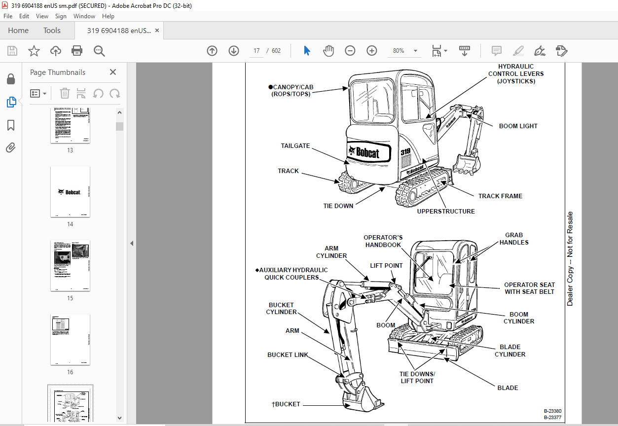
EXCAVATOR IDENTIFICATION 17
SAFETY AND MAINTENANCE 19
LIFTING AND BLOCKING THE EXCAVATOR 21
Procedure 21
UPPERSTRUCTURE SLEW LOCK 23
Operation 23
LIFTING THE EXCAVATOR 25
Procedure 25
OPERATOR CAB (ROPS / TOPS) 27
Description 27
Cab Door 27
Front Window 28
Front Wiper 30
Window Washer Reservoir 30
Right Side Window 31
Heater 32
TRANSPORTING THE EXCAVATOR ON A TRAILER 33
Loading And Unloading 33
Fastening 33
TAILGATE 35
Opening And Closing 35
Adjusting The Bumper 35
Adjusting The Latch 35
SERVICE SCHEDULE 37
Chart 37
AIR CLEANER SERVICE 39
Daily Check 39
Replacing Filter Elements 39
ENGINE COOLING SYSTEM 41
Cleaning 41
Checking Level 41
Removing And Replacing Coolant 42
FUEL SYSTEM 45
Fuel Specifications 45
Filling The Fuel Tank 45
Fuel Filters 46
Draining The Fuel Tank 46
Removing Air From The Fuel System 47
ENGINE LUBRICATION SYSTEM 49
Checking And Adding Engine Oil 49
Engine Oil Chart 49
Removing And Replacing Oil And Filter 50
HYDRAULIC SYSTEM 51
Checking And Adding Fluid 51
Hydraulic Fluid Chart 51
Removing And Replacing Hydraulic Filter 52
Removing And Replacing Hydraulic Fluid 52
LUBRICATING THE EXCAVATOR 55
Lubrication Locations 55
TRAVEL MOTOR 59
Checking And Adding Oil 59
Removing And Replacing Oil 59
SPARK ARRESTOR MUFFLER 61
Cleaning Procedure 61
ALTERNATOR BELT 63
Belt Adjustment 63
Belt Replacement 64
SEAT BELT 65
Inspection And Maintenance 65
PIVOT PINS 67
Inspection And Maintenance 67
EXCAVATOR STORAGE AND RETURN TO SERVICE 69
Storage 69
Return to Service 69
STOPPING THE ENGINE AND LEAVING THE EXCAVATOR 71
Procedure 71
Emergency Exits 72
HYDRAULIC SYSTEM 73
HYDRAULIC/HYDROSTATIC SCHEMATICS 77
HYDRAULIC SYSTEM INFORMATION 80
Glossary Of Hydraulic / Hydrostatic Symbols 80
Troubleshooting The Hydraulic Circuit 84
Troubleshooting The Cylinder Circuit 85
Troubleshooting The Swing (Upperstructure Slew) Circuit 86
Troubleshooting The Travel Circuit 87
BOOM CYLINDER 88
Testing 88
Removal and Installation 89
Parts Identification 91
Disassembly 92
Assembly 94
ARM CYLINDER 98
Testing 98
Removal and Installation 100
Parts Identification 101
Disassembly 102
Assembly 104
BOOM SWING CYLINDER 108
Testing 108
Removal and Installation 109
Parts Identification 111
Disassembly 112
Assembly 114
BUCKET CYLINDER 118
Testing 118
Removal and Installation 119
Parts Identification 121
Disassembly 122
Assembly 124
BLADE CYLINDER 128
Testing 128
Removal and Installation 129
Parts Identification 131
Disassembly 132
Assembly 134
TRACK FRAME EXPANSION CYLINDER 138
Testing 138
Removal And Installation 139
Parts Identification 143
Disassembly 144
Assembly 146
MAIN RELIEF VALVE 150
Testing And Adjusting The Main Relief Valve 150
PORT RELIEF VALVES 152
Testing And Adjusting The Port Relief Valve Pressure 152
CROSSPORT RELIEF VALVES 154
Testing And Adjusting The Crossport Relief Valve 154
PRESSURE REDUCING VALVE 156
Testing And Adjusting The Pressure Reducing Valve 156
HYDRAULIC CONTROL VALVE 158
Description 158
Removal and Installation 158
Identification Chart 162
Disassembly 163
Blade Valve Section Disassembly And Assembly 164
Slew Valve Section Disassembly And Assembly 169
Left Travel Valve Section Disassembly and Assembly 173
Boom Valve Section Disassembly and Assembly 177
Auxiliary Valve Section Disassembly And Assembly 180
Bucket Valve Section Disassembly and Assembly 184
Arm Valve Section Disassembly and Assembly 187
Boom Swing Valve Section Disassembly And Assembly 190
Right Travel Valve Section Disassembly And Assembly 194
Assembly 198
HYDRAULIC PUMP 204
Description 204
Testing The Hydraulic Pump 204
Removal And Installation 206
Parts Identification 208
Disassembly 209
Assembly 211
MANIFOLD ASSEMBLY/ACCUMULATOR 216
Description 216
Removal and Installation 216
Parts Identification 218
Disassembly 219
Assembly 226
TRAVEL MOTOR 234
Description 234
Removal and Installation 234
Parts Identification 235
Disassembly 236
Assembly 243
SWIVEL JOINT 252
Description 252
Removal And Installation 252
Parts Identification 255
Disassembly 256
Assembly 258
SWING MOTOR 262
Description 262
Removal and Installation 262
Parts Identification 263
Disassembly 264
Assembly 270
RIGHT CONTROL LEVER (JOYSTICK) 278
Description 278
Testing 278
Handle Removal And Installation 280
Removal And Installation 281
Parts Identification 282
Disassembly 283
Assembly 288
LEFT CONTROL LEVER (JOYSTICK) 292
Description 292
Testing 292
Handle Removal And Installation 294
Removal And Installation 296
Parts Identification 297
Disassembly 298
Assembly 303
HYDRAULIC FILTER 308
Description 308
Housing Removal and Installation 308
HYDRAULIC RESERVOIR 310
Description 310
Removal and Installation 310
OIL COOLER 312
Description 312
Removal And Installation 312
BLADE/TRACK EXPANSION SOLENOID BLOCK 314
Description 314
Block Removal and Installation 314
Solenoid Removal and Installation 315
Block Disassembly And Assembly 316
UNDERCARRIAGE 318
BLADE 320
Description 320
Extension Removal And Installation 320
Blade Removal And Installation 321
TRACK FRAME COMPONENTS 322
Description 322
Track Lug Height 322
Checking Tension 323
Adjusting Tension 324
Track Removal And Installation 325
Idler (Front) Removal And Installation 326
Idler (Front) Parts Identification 327
Idler (Front) Disassembly 328
Idler (Front) Assembly 329
Track Tension Grease Cylinder Parts Identification 331
Track Tension Grease Cylinder Disassembly And Assembly 332
Roller Removal And Installation 332
Roller Parts Identification 333
Roller Disassembly 334
Roller Assembly 336
Track Guide Removal And Installation 338
Sprocket Removal And Installation 338
Frame Removal And Installation 339
Track Damage Identification 340
SWING CIRCLE GEAR 350
Removal and Installation 350
UPPERSTRUCTURE & SWING SECTION 352
UPPERSTRUCTURE 356
Description 356
Removal 356
Installation 358
CANOPY 360
Removal And Installation 360
CAB 364
Removal And Installation 364
Door Removal And Installation 368
Front Window Removal And Installation 369
Right Side Rear Sliding Window Removal And Installation 372
Right Side Front Sliding Window Removal And Installation 373
Glass Removal 373
Right Side Front And Rear Sliding Window Weather Strip Removal And Installation 374
Right Side Front And Rear Sliding Window Wiper Strip Removal And Installation 374
Glass Installation 375
SEAT AND SEAT MOUNT 378
Seat Mount Removal And Installation 378
RIGHT CONSOLE 380
Description 380
Joystick Console Cover (Bottom) Removal And Installation 380
Joystick Console Cover (Top) Removal And Installation 381
Joystick Console Cover (Top) Disassembly And Assembly 382
Compression Spring Removal And Installation (Canopy Only) 383
Compression Spring Disassembly And Assembly (Canopy Only) 384
Lever Removal And Installation (Canopy Only) 385
Joystick Console Frame Removal And Installation 387
Joystick Console Frame Disassembly And Assembly 388
Right Rear Console Cover Removal And Installation 389
Right Rear Console Cover Disassembly and Assembly 390
Right Rear Console Frame Removal And Installation 391
LEFT CONSOLE 394
Description 394
Joystick Console Cover (Bottom) Removal And Installation 394
Joystick Console Cover (Top) Removal And Installation 395
Compression Spring Removal And Installation 396
Compression Spring Disassembly And Assembly 397
Lever Removal And Installation 399
Joystick Console Frame Removal And Installation 400
Joystick Console Frame Disassembly And Assembly 401
Left Rear Console Cover Removal And Installation 401
Left Rear Console Frame Removal And Installation 402
BLADE CONTROL 404
Removal and Installation 404
Disassembly And Assembly 405
Cable Removal and Installation 407
UPPERSTRUCTURE SLEW LOCK 408
Removal and Installation 408
Disassembly And Assembly 408
CONTROL LINKAGE ASSEMBLY 410
Description 410
Removal And Installation 410
Right Half of Control Linkage Disassembly And Assembly 412
Left Half of Control Linkage Disassembly And Assembly 414
Bracket of Control Linkage Disassembly And Assembly 417
FLOOR MAT AND FLOOR PANELS 418
Description 418
Rear Floor Panel Removal and Installation 418
Front Floor Panel Removal and Installation 419
Linkage Rod Removal And Installation 420
Linkage Rod Adjustment 420
Boom Swing Pedal Removal And Installation 422
Boom Swing Pedal Disassembly And Assembly 423
Right Travel Lever Removal And Installation 424
Right Travel Lever Disassembly And Assembly 424
Left Travel Lever Removal And Installation 425
Left Travel Lever Disassembly And Assembly 425
Auxiliary Pedal Removal And Installation (If Equipped) 426
Auxiliary Pedal Disassembly And Assembly (If Equipped) 426
Auxiliary Pedal Disassembly And Assembly (If Equipped) 427
FUEL TANK 428
Removal and Installation 428
HORN 430
Removal and Installation 430
SWING FRAME 432
Description 432
Removal And Installation 432
Bushing Removal and Installation 433
Swing Frame Bushing Removal 434
Swing Frame Bushing Installation 435
Boom Pivot Bushing Removal 435
Boom Pivot Bushing Installation 436
BOOM 438
Description 438
Removal And Installation 438
Boom Bushing Removal And Installation 439
ARM 440
Description 440
Removal And Installation 440
Arm To Boom Bushing Removal And Installation 441
Arm To Bucket And Bucket Link Bushing Removal And Installation 442
BUCKET 444
Removal And Installation 444
TAILGATE 446
Removal And Installation 446
Latch Removal And Installation 447
ELECTRICAL SYSTEM AND ANALYSIS 448
ELECTRICAL SCHEMATICS 450
ELECTRICAL SYSTEM INFORMATION 451
Glossary Of Electrical Symbols 451
Troubleshooting 454
Description 455
Fuse And Relay Location / Identification 455
Fuel Timer And Diode Location / Identification 456
BATTERY 457
Removal and Installation 457
Servicing 458
Using A Booster Battery (Jump Starting) 459
ALTERNATOR 461
Belt Adjustment 461
Charging System Inspection 462
Description 463
Tests 464
Alternator Output Test 464
Full Field Test 465
Alternator Regulator Test 465
Alternator Regulator Test With Voltmeter 466
Removal And Installation 466
Parts Identification 468
STARTER 469
Removal And Installation 469
Parts Identification 470
LIGHTS 471
UpperStructure Light Removal And Installation 471
UpperStructure Light Disassembly and Assembly 471
Boom Light Removal And Installation 472
Boom Light Disassembly And Assembly 472
Light Switch Removal And Installation 473
MICROSWITCH 475
Testing Left Console Microswitch 475
Left Console Microswitch Removal And Installation 476
Testing Right Console Microswitch 476
Right Console Microswitch Removal And Installation 478
FUEL LEVEL SENDER 479
Testing 479
Removal and Installation 479
ENGINE SERVICE 481
ENGINE INFORMATION 485
Description 485
Specifications 486
Engine 486
Fuel Injector Nozzles 486
Fuel Injection Pump 486
Cylinder Head 486
Valves 486
Valve Springs 486
Rocker Arms 487
Camshaft 487
Cylinders 487
Piston Rings 487
Pistons 488
Connecting Rods 488
Crankshaft 488
Oil Pump 488
Thermostat 489
Torque Values 490
Troubleshooting 491
Engine Removal and Installation 492
Engine Mount Replacement 499
Compression – Checking 500
ENGINE SPEED CONTROL 501
Removal and Installation 501
Cable Removal and Installation 502
SPARK ARRESTOR MUFFLER 505
Removal And Installation 505
AIR CLEANER 507
Housing Removal And Installation 507
ENGINE COOLING SYSTEM 509
Radiator Removal And Installation 509
Water Pump Removal And Installation 514
Water Pump Disassembly And Assembly 514
Thermostat Removal And Installation 515
Testing The Thermostat 515
LUBRICATION SYSTEM 517
Oil Pan Removal And Installation 517
Oil Pump Removal And Installation 518
Oil Pump Inspection 518
Engine Oil Pressure – Testing 519
Relief Valve 520
FUEL SYSTEM 521
Fuel Camshaft Removal And Installation 521
Fuel Camshaft Governor Disassembly And Assembly 521
Fuel Shutoff Solenoid – Checking 522
Fuel Shutoff Solenoid – Removal And Installation 522
Fuel Shutoff Timer Removal And Installation 523
Fuel Injection Pump – Checking 523
Fuel Injection Pump Removal And Installation 524
Injection Pump – Timing 526
Fuel Injector Removal And Installation 528
Fuel Injector Nozzle Pressure – Checking 529
Nozzle Spray Condition 530
Valve Seat Tightness 530
CYLINDER HEAD 531
Glow Plug Removal And Installation 531
Glow Plugs – Testing 532
Valve Clearance Adjustment 532
Valve Timing, Checking 533
Cylinder Head Removal And Installation 534
Cylinder Head Disassembly And Assembly 536
Cylinder Head – Servicing 537
Cylinder Head Top Clearance 538
Valve Guide – Checking 538
Reconditioning The Valve And Valve Seat 540
Valve Spring 541
Valve Tappets 542
Rocker Arm And Shaft – Checking 543
CRANKSHAFT AND PISTONS 545
Piston And Connecting Rod Removal And Installation 545
Piston And Connecting Rod – Servicing 547
Cylinder Bore Checking 549
Connecting Rod Alignment 549
Crankshaft Gear Removal And Installation 550
Crankshaft And Bearings Removal And Installation 551
Crankshaft And Bearings – Servicing 553
CAMSHAFT AND TIMING GEARS 555
Timing Gearcase Cover Removal And Installation 555
Timing Gears Backlash – Checking 557
Idler Gear And Shaft Removal And Installation 557
Camshaft – Servicing 558
Idler Gear And Shaft Servicing 560
FLYWHEEL AND HOUSING 561
Flywheel Housing Removal And Installation 561
Hydraulic Pump Coupler Removal And Installation 562
Flywheel Removal 562
Flywheel Installation 563
Rear End Plate Removal And Installation 563
HEATER 565
HEATER SYSTEM 567
Description 567
Components 567
REGULATOR MAINTENANCE 569
Filter Element Removal And Installation 569
Heater Coil 569
HEATER UNIT 571
Removal And Installation 571
Louver Removal and Installation 572
Threaded Insert Removal And Installation 572
HEATER COIL 573
Removal And Installation 573
HEATER FAN 577
Removal And Installation 577
HEATER VALVE 581
Removal And Installation 581
SPECIFICATIONS 583
319 EXCAVATOR SPECIFICATIONS 585
Dimensions 585
Performance 587
Controls 587
Engine 587
Hydraulic System 588
Hydraulic Cylinders 588
Hydraulic Cycle Times 588
Electrical 588
Instrumentation 588
Drive System 589
Slew System 589
Undercarriage 589
Crawler Track Design 589
Capacities 589
Fuel Tank 589
Tracks 589
Type 589
Ground Pressure 589
TORQUE SPECIFICATIONS FOR BOLTS 591
Torque For General SAE Bolts 591
Torque For General Metric Bolts 592
HYDRAULIC CONNECTION SPECIFICATIONS 593
O-ring Face Seal Connection 593
Straight Thread O-ring Fitting 594
Tubelines And Hoses 594
Flare Fitting 595
Port Seal Fitting 596
HYDRAULIC FLUID SPECIFICATIONS 597
Specifications 597
CONVERSIONS 599
Decimal And Millimeter Equivalents 599
U S To Metric Conversion Chart 599
SMR 601
319-1 601
IMAGES PREVIEW OF THE MANUAL:


VIDEO PREVIEW OF THE MANUAL:
PLEASE NOTE:
- This is the SAME manual used by the dealers to troubleshoot any faults in your vehicle. This can be yours in 2 minutes after the payment is made.
- Contact us at [email protected] should you have any queries before your purchase or that you need any other service / repair / parts operators manual.
S.M


