

Audi Q5 2017 – 2020 Complete Service Repair Workshop Manual
IMAGES PREVIEW OF THE MANUAL:

VIDEO PREVIEW:

DESCRIPTION:
00-General Information:
This is the General Information Section of the 2017-2020 Audi Q5 Factory Service Manual.
01-Engine Mechanical:
This is the Engine Mechanical Section of the 2017-2020 Audi Q5 Factory Service Manual.
02-Engine Servicing:
This is the Engine Servicing Section of the 2017-2020 Audi Q5 Factory Service Manual.
03-Fuel Supply System:
This is the Fuel Supply System Section of the 2017-2020 Audi Q5 Factory Service Manual.
04-Transmissions:
This is the Transmissions Section of the 2017-2020 Audi Q5 Factory Service Manual.
05-Axles, Suspension & Steering:
This is the Axles, Suspension & Steering Section of the 2017-2020 Audi Q5 Factory Service Manual.
06-Brake System:
This is the Brake System Section of the 2017-2020 Audi Q5 Factory Service Manual.
07-HVAC:
This is the Heating & Air Conditioning Section of the 2017-2020 Audi Q5 Factory Service Manual.
08-Communication-Audio:
This is the Communication-Audio Section of the 2017-2020 Audi Q5 Factory Service Manual.
09-Electrical System:
This is the Electrical System Section of the 2017-2020 Audi Q5 Factory Service Manual.
10-Body Repairs:
This is the Body Repairs Section of the 2017-2020 Audi Q5 Factory Service Manual.
11-Audi QS FSM 2017-2020 Complete:
This is the complete 2017-2020 Audi Q5 Factory Service Manual. It contains 8,989 pages of service information.
TABLE OF CONTENTS:
00 – Technical data 1
1 Identification 1
2 Safety precautions 2
3 Repair instructions 3
10 – Removing and installing engine 4
1 Removing and installing engine 4
11 Removing engine 4
12 Securing engine to engine and gearbox support 18
13 Installing engine 18
2 Assembly mountings 26
21 Exploded view – assembly mountings 26
22 Supporting engine in installation position 29
23 Removing and installing engine mountings 30
24 Removing and installing gearbox mounting 32
3 Engine cover panel34
13 – Crankshaft group35
1 Cylinder block (pulley end)35
11 Exploded view – cylinder block (pulley end) 35
12 Exploded view – sealing flange (pulley end) 35
13 Removing and installing poly V-belt 35
14 Removing and installing poly V-belt tensioner 35
15 Removing and installing vibration damper35
16 Removing and installing bracket for ancillaries 35
17 Removing and installing engine support 36
18 Removing and installing sealing flange (pulley end) 38
2 Cylinder block (gearbox end) 39
3 Crankshaft40
4 Pistons and conrods 41
15 – Cylinder head, valve gear 42
1 Toothed belt drive42
2 Cylinder head 43
3 Valve gear44
4 Inlet and exhaust valves 45
17 – Lubrication 46
1 Sump/oil pump 46
11 Exploded view – sump/oil pump 46
12 Engine oil46
13 Removing and installing sump 46
14 Removing and installing oil pump46
15 Removing and installing oil level and oil temperature sender G266 47
2 Engine oil cooler 48
3 Oil filter/oil pressure switches 49
19 – Cooling 50
1 Cooling system/coolant 50
11 Connection diagram – coolant hoses 50
12 Checking cooling system for leaks53
Audi Q5 2017 ➤
4-cylinder TDI engine, 20 ltr 4-valve common rail (EA 288 Gen I) – Edition 112019
Contents i
13 Draining and filling cooling system53
2 Coolant pump/thermostat assembly 62
21 Exploded view – coolant pump/thermostat62
22 Exploded view – electric coolant pump 62
23 Exploded view – coolant temperature senders 63
24 Removing and installing electric coolant pump 63
25 Removing and installing coolant pump 66
26 Removing and installing thermostat 66
27 Checking thermostat 66
28 Removing and installing coolant valve for cylinder head N489 66
29 Removing and installing coolant temperature sender G62 66
3 Coolant pipes 67
31 Exploded view – coolant pipes 67
32 Removing and installing coolant pipes 70
33 Removing and installing coolant pipes for gearbox 82
4 Radiators/radiator fans 84
41 Exploded view – radiators/radiator fans 84
42 Removing and installing radiator86
43 Removing and installing water radiator for charge air cooling circuit 89
44 Removing and installing radiator cowl 92
45 Removing and installing radiator fan V796
21 – Turbocharging/supercharging 98
1 Turbochargers 98
2 Charge air system99
23 – Mixture preparation – injection 100
1 Injection system 100
11 Overview – fuel system 100
12 Overview of fitting locations – injection system 101
13 Filling and bleeding fuel system 107
14 Checking fuel system for leaks 107
2 Vacuum system 108
21 Connection diagram – vacuum system 108
22 Checking vacuum system108
3 Air cleaner109
31 Exploded view – air cleaner housing 109
32 Removing and installing air cleaner housing 110
4 Intake manifold 112
5 Injectors/high-pressure reservoir (rail) 113
6 High-pressure pump 114
7 Senders and sensors 115
71 Removing and installing air mass meter G70 115
72 Removing and installing fuel temperature sender G81 116
73 Removing and installing fuel pressure sender G247 116
74 Checking fuel pressure regulating valve N276 116
75 Removing and installing fuel pressure regulating valve N276 116
76 Removing and installing pressure differential sender G505 116
8 Lambda probe 117
9 Engine control unit118
91 Exploded view – engine control unit 118
92 Removing and installing engine/motor control unit J623118
26 – Exhaust system120
Audi Q5 2017 ➤
4-cylinder TDI engine, 20 ltr 4-valve common rail (EA 288 Gen I) – Edition 112019
ii Contents
1 Exhaust pipes/silencers 120
11 Exploded view – silencers120
12 Removing and installing front exhaust pipe 123
13 Separating exhaust pipes/silencers 126
14 Removing and installing silencers127
15 Stress-free alignment of exhaust system128
16 Checking exhaust system for leaks 129
2 Emission control system 130
3 SCR (selective catalytic reduction) system 131
31 Exploded view – reducing agent tank 131
32 Exploded view – control unit for SCR system 133
33 Exploded view – delivery unit 134
34 Exploded view – reducing agent supply line 134
35 Releasing pressure in SCR system 135
36 Draining reducing agent tank 135
37 Removing and installing reducing agent tank 138
38 Removing and installing injector for reducing agent N474 142
39 Removing and installing control unit for reducing agent metering system J880142
310 Removing and installing pump for reducing agent V437142
311 Removing and installing pressure sender for reducing agent metering system G686 146
312 Removing and installing connection for SCR supply line149
313 Resetting SCR learnt values 151
4 Exhaust gas temperature control152
5 Exhaust gas recirculation153
28 – Glow plug system154
1 Glow plug system154
11 Exploded view – glow plug system154
12 Removing and installing glow plug154
13 Removing and installing automatic glow period control unit J179154
14 Removing and installing Hall sender G40154
15 Removing and installing engine speed sender G28 154
Audi Q5 2017 ➤
4-cylinder TDI engine, 20 ltr 4-valve common rail (EA 288 Gen I) – Edition 112019
Contents
00 – Technical data 1
1 Identification 1
11 Engine number/engine data 1
2 Safety precautions2
21 Safety precautions when working on the fuel supply system 2
22 Safety precautions when working on vehicles with start/stop system 2
23 Safety precautions when using testers and measuring instruments during a road test 3
24 Safety precautions when working on the cooling system3
25 Safety precautions when working on the exhaust system3
26 Safety precautions when working on the SCR system 4
27 Safety precautions when working on the subframe 5
3 Repair instructions6
31 Rules for cleanliness 6
32 General notes 6
33 General repair instructions7
34 Bolts and nuts 8
35 Foreign particles in engine8
36 Contact corrosion9
37 Routing and attachment of pipes, hoses and wiring 9
38 Installing radiators and condensers 9
10 – Removing and installing engine10
1 Removing and installing engine 10
11 Removing engine10
12 Securing engine to engine and gearbox support10
13 Installing engine 11
2 Assembly mountings 12
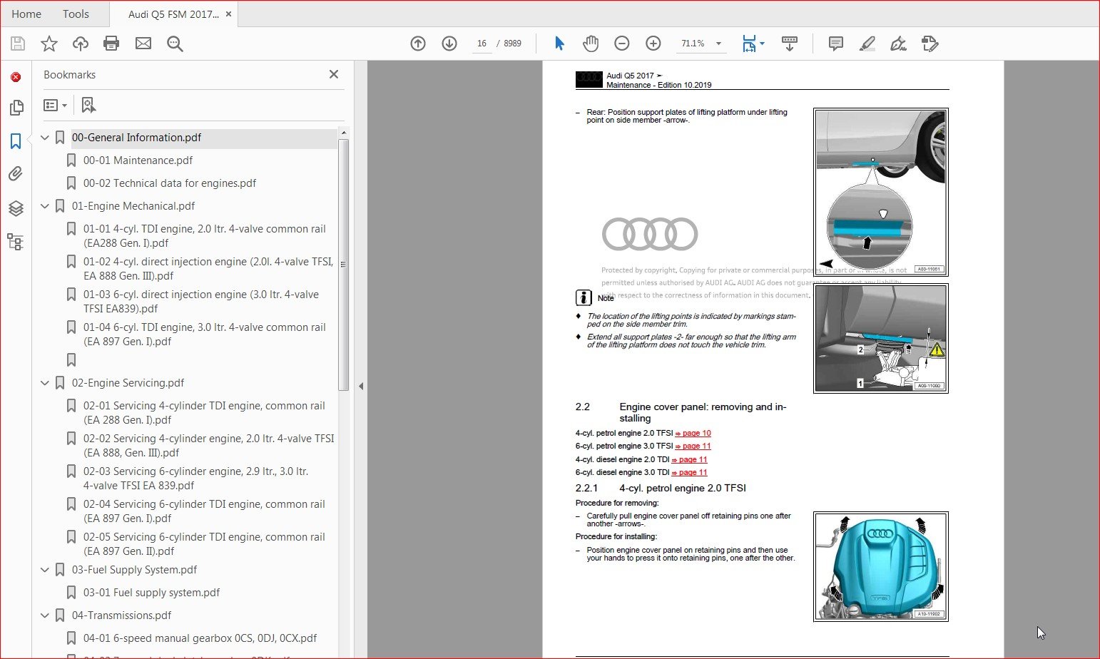
3 Engine cover panel13
31 Removing and installing engine cover panel 13
13 – Crankshaft group14
1 Cylinder block (pulley end)14
11 Exploded view – cylinder block (pulley end) 14
12 Exploded view – sealing flange (pulley end) 16
13 Removing and installing poly V-belt 17
14 Removing and installing tensioner for poly V-belt18
15 Removing and installing vibration damper19
16 Removing and installing bracket for ancillaries 21
17 Removing and installing engine support22
18 Removing and installing sealing flange (pulley end) 22
2 Cylinder block (gearbox end) 26
21 Exploded view – cylinder block (gearbox end) 26
22 Removing and installing drive plate 27
23 Removing and installing sealing flange (gearbox end) 28
3 Crankshaft35
31 Crankshaft dimensions 35
32 Measuring axial clearance of crankshaft35
4 Pistons and conrods 36
41 Exploded view – pistons and conrods 36
42 Removing and installing pistons 38
43 Measuring piston projection at TDC 40
44 Checking pistons and cylinder bores 41
Audi A4 2015 ➤ , Audi A4 Avant 2015 ➤ , Audi A5 2016 ➤ , Audi A6 2019 ➤
Servicing 4-cylinder TDI engine, common rail (EA 288 Gen I) – Edition 022019
Contents i
45 Separating parts of new conrod 42
46 Checking radial clearance of conrod bearings 43
15 – Cylinder head, valve gear 44
1 Toothed belt drive44
11 Exploded view – toothed belt cover 44
12 Exploded view – toothed belt 45
13 Removing and installing toothed belt cover 46
14 Detaching toothed belt from camshaft 48
15 Removing and installing toothed belt 54
2 Cylinder head 63
21 Exploded view – cylinder head 63
22 Exploded view – cylinder head cover 65
23 Removing and installing cylinder head 66
24 Removing and installing cylinder head cover 72
25 Removing and installing seals for injectors 74
26 Removing and installing camshaft housing 75
27 Checking compression 79
3 Valve gear82
31 Exploded view – valve gear 82
32 Removing and installing camshaft oil seal83
33 Removing and installing valve stem oil seals 86
4 Inlet and exhaust valves 94
41 Checking valve guides 94
42 Checking valves 94
43 Valve dimensions95
17 – Lubrication 96
1 Sump/oil pump 96
11 Exploded view – sump/oil pump 96
12 Engine oil98
13 Removing and installing sump 98
14 Removing and installing oil pump101
15 Removing and installing oil level and oil temperature sender G266 101
2 Engine oil cooler 102
3 Oil filter/oil pressure switches 103
31 Exploded view – oil filter housing/oil pressure switch 103
32 Removing and installing oil pressure switch F22104
33 Removing and installing oil pressure switch for reduced oil pressure F378 106
34 Removing and installing oil filter housing107
35 Removing and installing valve for oil pressure control N428 109
36 Checking oil pressure 110
19 – Cooling 112
1 Cooling system/coolant 112
11 Connection diagram – coolant hoses 112
12 Checking cooling system for leaks112
13 Draining and filling cooling system115
2 Coolant pump/thermostat assembly 116
21 Exploded view – coolant pump/thermostat116
22 Exploded view – electric coolant pump 117
23 Exploded view – coolant temperature senders 118
24 Removing and installing electric coolant pump 118
25 Removing and installing coolant pump 119
26 Removing and installing thermostat 119
Audi A4 2015 ➤ , Audi A4 Avant 2015 ➤ , Audi A5 2016 ➤ , Audi A6 2019 ➤
Servicing 4-cylinder TDI engine, common rail (EA 288 Gen I) – Edition 022019
ii Contents
27 Checking thermostat 119
28 Removing and installing coolant valve for cylinder head N489 119
29 Removing and installing coolant temperature sender G62 120
3 Coolant pipes 123
4 Radiator/radiator fans 124
21 – Turbocharging/supercharging 125
1 Turbocharger 125
11 Exploded view – turbocharger 125
12 Removing and installing turbocharger 128
13 Renewing vacuum unit for turbocharger132
2 Charge air system138
21 Exploded view – charge air system138
22 Exploded view – hose connections for charge air system140
23 Removing and installing charge pressure sender G31 141
24 Removing and installing charge air temperature sender141
25 Checking charge air system for leaks 142
23 – Mixture preparation – injection 147
1 Injection system 147
11 Overview – fuel system 147
12 Overview of fitting locations – injection system 147
13 Filling and bleeding fuel system 147
14 Checking fuel system for leaks 148
2 Vacuum system 149
21 Connection diagram – vacuum system 149
22 Checking vacuum system149
3 Air cleaner150
4 Intake manifold 151
41 Exploded view – intake manifold 151
42 Removing and installing throttle valve module J338 153
43 Removing and installing intake manifold155
5 Injectors/high-pressure reservoir (rail) 160
51 Exploded view – injectors160
52 Exploded view – high-pressure reservoir (rail) 163
53 Checking injectors164
54 Performing adaption of correction values for injectors 164
55 Checking for injectors sticking open 165
56 Checking return flow rate of injectors with engine running167
57 Checking return flow rate of injectors at starter cranking speed170
58 Removing and installing injectors172
59 Removing and installing high-pressure pipes 175
510 Removing and installing high-pressure reservoir (rail) 178
6 High-pressure pump 180
61 Exploded view – high-pressure pump 180
62 Removing and installing high-pressure pump 181
7 Senders and sensors 185
71 Removing and installing air mass meter G70 185
72 Removing and installing fuel temperature sender G81 185
73 Removing and installing fuel pressure sender G247 186
74 Checking fuel pressure regulating valve N276 188
75 Removing and installing fuel pressure regulating valve N276 189
76 Removing and installing pressure differential sender G505 191
77 Removing and installing exhaust gas pressure sensor 1 G450193
Audi A4 2015 ➤ , Audi A4 Avant 2015 ➤ , Audi A5 2016 ➤ , Audi A6 2019 ➤
Servicing 4-cylinder TDI engine, common rail (EA 288 Gen I) – Edition 022019
Contents iii
8 Lambda probe 194
81 Exploded view – Lambda probe 194
82 Removing and installing Lambda probe 195
83 Removing and installing NOx sender 197
9 Engine control unit200
26 – Exhaust system201
1 Exhaust pipes/silencers 201
11 Exploded view – silencers201
12 Removing and installing front exhaust pipe 201
13 Separating exhaust pipes/silencers 201
14 Removing and installing silencers201
15 Stress-free alignment of exhaust system201
16 Checking exhaust system for leaks 201
2 Emission control system 202
21 Exploded view – emission control system202
22 Removing and installing catalytic converter 203
23 Removing and installing emission control module205
24 Removing and installing exhaust flap control unit J883214
3 SCR (selective catalytic reduction) system 215
31 Exploded view – reducing agent tank 215
32 Exploded view – control unit for SCR system 215
33 Exploded view – delivery unit 215
34 Exploded view – reducing agent supply line 215
35 Releasing pressure in SCR system 216
36 Draining reducing agent tank 217
37 Removing and installing reducing agent tank 217
38 Removing and installing injector for reducing agent N474 217
39 Removing and installing control unit for reducing agent metering system J880218
310 Removing and installing pump for reducing agent V437219
311 Removing and installing pressure sender for reducing agent metering system G686 219
312 Removing and installing connection for SCR supply line219
313 Adapting SCR learnt values 219
4 Exhaust gas temperature control221
41 Exploded view – exhaust gas temperature control221
42 Removing and installing exhaust gas temperature sender 1 G235 222
43 Removing and installing exhaust gas temperature sender 2 G448 223
44 Removing and installing exhaust gas temperature sender 3 G495 225
45 Removing and installing exhaust gas temperature sender 4 G648 226
5 Exhaust gas recirculation228
51 Exploded view – exhaust gas recirculation system228
52 Removing and installing exhaust gas recirculation control motor V338230
53 Removing and installing exhaust gas recirculation control motor 2 V339231
54 Removing and installing exhaust gas recirculation cooler232
55 Checking exhaust gas recirculation cooler for leaks 234
56 Removing and installing exhaust gas recirculation temperature sensor G98 237
28 – Glow plug system239
1 Glow plug system239
11 Exploded view – glow plug system239
12 Removing and installing glow plug240
13 Removing and installing automatic glow period control unit J179243
14 Removing and installing Hall sender G40243
15 Removing and installing engine speed sender G28 243
00 – Technical data 1
1 Safety precautions1
11 Safety precautions when working on the fuel system 1
12 Safety precautions when working on the high-voltage system 2
13 Safety precautions when working in the vicinity of high-voltage components 2
14 Safety precautions when working on vehicles with start/stop system 3
15 Safety precautions when using testers and measuring instruments during a road test 3
16 Safety precautions when working on the SCR system 3
2 Repair instructions5
21 Rules for cleanliness 5
22 Test conditions 5
23 Contact corrosion6
24 Routing and attachment of pipes, hoses and wiring 6
25 Identification plates6
26 Use of impact wrenches 6
27 Nuts, bolts7
20 – Fuel supply system 8
1 Safety precautions8
2 Fuel tank 9
21 Exploded view – fuel tank9
22 Draining fuel tank12
23 Removing and installing fuel tank19
24 Removing and installing misfuelling prevention device 29
25 Deactivating misfuelling prevention device 32
3 Fuel delivery unit/fuel gauge senders 33
31 Exploded view – fuel delivery unit/fuel gauge senders 33
32 Removing and installing fuel delivery unit/fuel gauge sender 37
33 Bleeding fuel line for metering pump 49
34 Removing and installing fuel gauge sender G 50
4 Plug-in connectors51
41 Disconnecting plug-in connectors51
5 Activated charcoal filter system 57
51 Connection diagram – activated charcoal filter system 57
52 Exploded view – activated charcoal filter system61
53 Removing and installing activated charcoal filter64
54 Removing and installing vent line with filter 65
55 Removing and installing fuel tank leak detection module GX3666
56 Removing and installing fuel tank shut-off valve N288 67
57 Removing and installing tank pressure sensor G400 68
58 Removing and installing control unit for fuel tank leak detection J909 69
59 Fuel tank – leak detection69
510 Checking fuel system for leaks – vehicles with fuel tank leak detection module GX36 70
6 Fuel filter 76
61 Exploded view – fuel filter76
62 Exploded view – water separator77
63 Removing and installing water separator79
7 Accelerator mechanism 82
71 Exploded view – accelerator pedal module82
72 Removing and installing accelerator pedal module GX283
8 Fuel pump84
81 Checking fuel system pressurisation pump G6 84
Audi Q5 2017 ➤ , Audi Q5 China 2019 ➤
Fuel supply system – Edition 122019
Contents i
82 Removing and installing suction-jet pump99
83 Removing and installing fuel pump control unit J538 100
Audi Q5 2017 ➤ , Audi Q5 China 2019 ➤
Fuel supply system – Edition 122019
ii
00 – Technical data 1
1 Identification 1
11 Gearbox identification 1
12 Identification – four-wheel drive coupling 0CJ or 0CX 3
2 Safety precautions4
21 Safety precautions when working on vehicles with start/stop system 4
22 Safety precautions when working on subframe 4
3 Repair instructions5
31 General repair instructions5
32 Contact corrosion8
4 Technical data 10
41 Allocation of gearbox to engine 10
42 Capacities15
5 Transmission layout 17
51 Transmission layout – front-wheel drive 17
52 Transmission layout – four-wheel drive 18
6 Electrical components 19
61 Overview of fitting locations – electrical components 19
30 – Clutch 20
1 Clutch mechanism20
11 Exploded view – pedal cluster 20
12 Exploded view – clutch hydraulics24
13 Removing and installing clutch pedal 26
14 Removing and installing over-centre spring 27
15 Removing and installing clutch master cylinder 29
16 Bleeding clutch hydraulics33
17 Checking clutch master cylinder and clutch slave cylinder 34
2 Clutch 36
21 Exploded view – clutch module 36
22 Tightening sequence – clutch module to drive plate 36
23 Removing and installing clutch module 39
24 Servicing clutch 39
34 – Controls, housing40
1 Selector mechanism 40
11 Overview – selector mechanism 40
12 Exploded view – gear knob and cover 41
13 Exploded view – selector mechanism 42
14 Removing and installing gear knob 43
15 Removing and installing selector mechanism 44
16 Adjusting selector mechanism 50
17 Checking selector mechanism 52
18 Renewing selector shaft oil seal 53
19 Removing and installing gear detection sensor G604 56
2 Removing and installing gearbox59
21 Removing gearbox59
22 Installing gearbox79
23 Tightening torques for gearbox 89
3 Assembly mountings 91
31 Exploded view – assembly mountings 91
32 Removing and installing tunnel cross member 92
Audi A4 2015 ➤ , Audi A4 Avant 2015 ➤ , Audi A5 2016 ➤ , Audi Q5 2017 ➤
6-speed manual gearbox 0CS, 0DJ, 0CX – Edition 102017
Contents i
Protected by copyright Copying for private or commercial purposes, in part or in whole, is not
permitted unless authorised by AUDI AG AUDI AG does not guarantee or accept any liability
with respect to the correctness of information in this document Copyright by AUDI AG
33 Removing and installing gearbox support with gearbox mounting93
34 Removing and installing gearbox mounting 94
4 Transporting gearbox 95
5 Dismantling and assembling gearbox 96
6 Gear oil 97
61 Checking gear oil level 97
62 Checking ATF level for four-wheel drive coupling101
35 – Gears, shafts 102
1 Dismantling and assembling gears and shafts 102
39 – Final drive – front differential 103
1 Oil seals 103
11 Overview of fitting locations – oil seals 103
12 Renewing oil seal (left-side) 104
13 Renewing oil seal (right-side) 104
14 Renewing oil seal for output shaft105
15 Renewing sealing cap for output shaft in gearbox cover106
2 Differential109
21 Removing and installing flange shaft (left-side) 109
22 Removing and installing flange shaft (right-side)109
3 Four-wheel drive coupling113
00 – Technical data 1
1 Identification 1
11 Identification of final drive1
12 Identification of four-wheel drive coupling 0CJ or 0CX 5
2 Technical data 7
21 Allocation of gearbox to engine 7
22 Capacities13
3 Transmission layout 16
31 Transmission layout – vehicles without four-wheel drive coupling16
32 Transmission layout – vehicles with four-wheel drive coupling »quattro ultra« 17
4 Safety precautions18
41 Safety precautions when working on vehicle 18
42 Safety precautions when working on vehicles with start/stop system 19
43 Safety precautions when working on high-voltage system19
44 Safety precautions when working in the vicinity of high-voltage components 20
5 Repair instructions21
51 General repair instructions21
52 Safety precautions and testing – rear final drive 0D3 “quattro sport” and 0BX “quattro sport”
21
53 Safety precautions and testing – four-wheel drive coupling 0CJ or 0CX24
54 Special tools 24
55 Components 24
56 Contact corrosion26
6 Electrical components 28
61 Overview of fitting locations – electrical components 28
39 – Final drive – rear differential 30
1 Propshaft30
11 Exploded view – propshaft30
12 Removing and installing propshaft32
13 Renewing protective boot47
2 Final drive50
21 Exploded view – final drive50
22 Removing and installing final drive55
23 Dismantling and assembling final drive 86
24 Hydraulic control unit, 0D3 “quattro sport” and 0BX “quattro sport” 94
25 Checking torque distribution – 0D3 “quattro sport” and 0BX “quattro sport” 103
3 Gear oil 104
31 Overview of fitting locations – drain and inspection plugs104
32 Checking gear oil level 107
33 Draining and filling gear oil109
4 ATF119
41 Checking ATF level 119
42 Draining and filling ATF 119
5 Oil seals 124
51 Overview of fitting locations – oil seals 124
52 Renewing oil seal (left-side) 131
53 Renewing oil seal (right-side) 138
54 Renewing input shaft oil seal 151
55 Renewing protective ring on flange shaft175
56 Renewing protective ring on propshaft flange 181
Audi A4 2015 ➤ , Audi A4 Avant 2015 ➤ , Audi A4 China 2016 ➤ , Audi A4 a
Rear final drive 0D2, 0D3, 0DB, 0B0, 0BX, 0DG, 0G2, 09R – Edition 092018
Contents i
6 Assembly mountings 184
61 Removing and installing bonded rubber bush 184
7 Four-wheel drive coupling186
71 Exploded view – four-wheel drive coupling186
72 Removing and installing four-wheel drive coupling 187
73 Additional work required if four-wheel drive coupling was renewed 190
74 Checking oil level191
75 Draining and filling fluid for four-wheel drive coupling 191
76 Removing and installing control unit 194
77 Additional work for “quattro ultra” vehicles196
78 Checking setting torque of four-wheel drive coupling 197
79 Renewing oil seal for four-wheel drive coupling output shaft 199
710 Renewing oil seal for four-wheel drive coupling input shaft 201
8 Gearbox control system 203
81 Overview of fitting locations – gearbox control system 203
82 Removing and installing all-wheel drive control unit J492 – vehicles with “quattro ultra”206
83 Removing and installing differential lock control unit J187 – vehicles with “quattro sport”
206
84 Additional work required after renewing differential lock control unit J187 208
00 – Technical data 1
1 General notes 1
11 Notes for repair work on the ABS1
2 Safety precautions2
21 Safety precautions when working on the high-voltage system 2
22 Safety precautions when working in the vicinity of high-voltage components 3
23 Safety precautions when working on vehicles with start/stop system 3
24 Safety precautions when using testers and measuring instruments during a road test 3
3 Repair notes 4
31 Identification plates4
32 Use of impact wrenches 4
33 Rules for cleanliness 4
34 General repair instructions5
35 Contact corrosion5
36 Brake fluid5
4 Technical data 6
41 Technical data for brakes6
5 Brake test8
51 General notes 8
52 Testing vehicles with front-wheel drive 8
53 Testing vehicles with four-wheel drive 9
54 Testing parking brake 9
45 – Anti-lock brake system 11
1 General notes 11
11 Notes for repair work on the ABS11
2 Overview of fitting locations 12
21 Overview of fitting locations – ABS/ESP 12
22 Fitting location of diagnostic connection 13
3 Control unit and hydraulic unit 14
31 Exploded view – control unit with hydraulic unit 14
32 Note for ABS control unit J104 15
33 Removing and installing ABS control unit J104 with ABS hydraulic unit N55 15
34 Separating control unit from hydraulic unit22
35 Attaching control unit to hydraulic unit 25
4 Sensors 28
41 Exploded view – front wheel speed sensor28
42 Exploded view – rear wheel speed sensor29
43 Removing and installing front wheel speed sensor G45 / G47 29
44 Removing and installing rear wheel speed sensor G44 / G46 30
45 Removing and installing brake light switch30
46 Checking ABS sensor ring31
46 – Brakes – mechanism 33
1 Front brakes 33
11 Exploded view – front brakes 33
12 Removing and installing brake pads 47
13 Removing and installing brake caliper 60
14 Renewing brake caliper 66
15 Removing and installing brake disc 78
16 Removing and installing splash plate 80
17 Removing and installing brake pad wear indicator wire 80
Audi Q5 2017 ➤
Brake system – Edition 032019
Contents i
2 Rear brakes 82
21 Exploded view – rear brakes 82
22 Removing and installing rear brake pads85
23 Removing and installing rear brake caliper 91
24 Renewing rear brake caliper 93
25 Removing and installing rear brake carrier97
26 Removing and installing rear brake disc98
27 Removing and installing rear splash plate100
3 Parking brake 101
31 Overview of fitting locations – parking brake 101
32 Removing and installing control unit for electromechanical parking brake J540102
33 Removing and installing parking brake motor V282 / V283 104
4 Manually releasing parking brake107
5 Brake pedal 108
51 Exploded view – brake pedal 108
52 Removing and installing mounting bracket112
53 Removing and installing brake pedal position sender G100 123
54 Separating brake pedal from brake servo124
55 Connecting brake pedal to brake servo 125
56 Removing and installing brake pedal 126
57 Removing and installing mounting for brake servo push rod 132
47 – Brakes – hydraulics 135
1 Front brake caliper135
11 Exploded view – front brake caliper (1LA/1LJ/1ZB/1ZT) 135
12 Removing and installing brake caliper piston 137
13 Renewing protective caps and guide pins141
2 Rear brake caliper143
21 Exploded view – rear brake caliper143
22 Removing and installing brake caliper piston 144
23 Renewing protective caps and guide pins147
3 Brake servo / brake master cylinder 149
31 Exploded view – brake servo / brake master cylinder 149
32 Brake fluid level warning contact F34 155
33 Removing and installing brake servo 156
34 Removing and installing brake master cylinder 162
35 Removing and installing brake fluid reservoir 165
36 Note on locking pin on brake fluid reservoir 165
37 Removing and installing brake fluid reservoir 166
38 Removing and installing brake system pressure accumulator VX70 168
4 Vacuum system 172
41 Exploded view – electric vacuum pump 172
42 Exploded view – vacuum pump 174
43 Checking non-return valve 175
44 Removing and installing brake servo pressure sensor 175
45 Checking vacuum system175
46 Removing and installing electric vacuum pump 179
47 Removing and installing vacuum pump 180
5 Brake lines188
51 Connection points188
52 Routing of brake lines 189
6 Hydraulic system191
61 General notes on brake fluid 191
62 Pre-bleeding hydraulic system 192
Audi Q5 2017 ➤
Brake system – Edition 032019
ii Contents
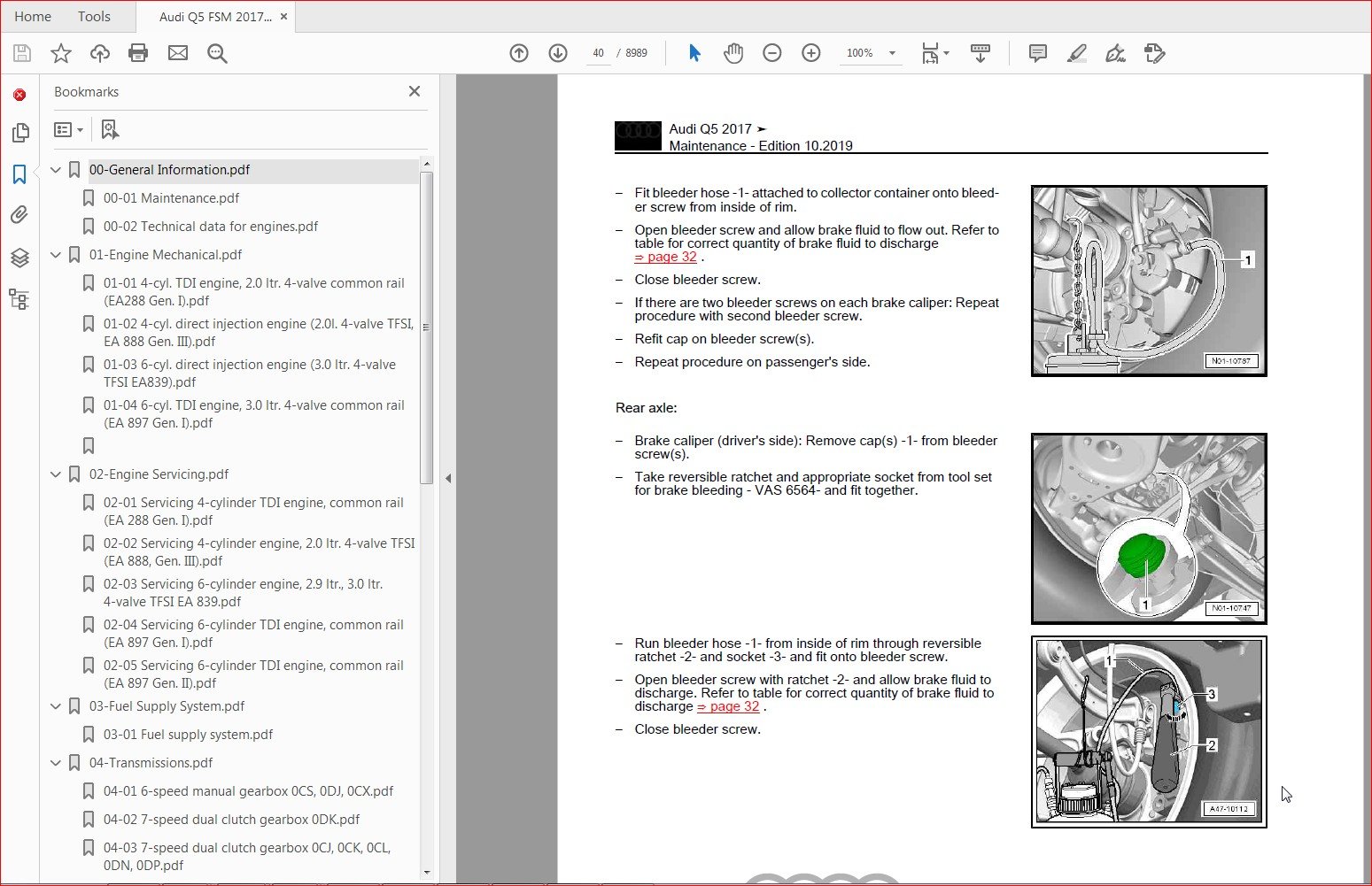
63 Bleeding hydraulic system192
64 Pre-bleeding brake system pressure accumulator VX70198
65 Leak test 199
Audi Q5 2017 ➤
Brake system – Edition 032019
Contents
Workshop Manual
Audi A4 2015 ➤ , Audi A4 Avant 2015 ➤ ,
Audi A4 China 2016 ➤ ,
Audi A4 allroad quattro 2016 ➤ ,
Audi A5 2016 ➤ , Audi Q5 2017 ➤ ,
Audi Q5 China 2019 ➤
Heating, air conditioning
Edition 062019
Service
Service Department Technical Information
List of Workshop Manual Repair Groups
R e p a i r Gr o u p
00 – Technical data
80 – Heating
87 – Air conditioning system
Technical information should always be available to the foremen and mechanics, because their
careful and constant adherence to the instructions is essential to ensure vehicle road-worthiness and
safety In addition, the normal basic safety precautions for working on motor vehicles must, as a
matter of course, be observed
Service
All rights reserved
No reproduction without prior agreement from publisher
Copyright © 2019 Audi AG, Ingolstadt D4B8058B01D
Contents
00 – Technical data 1
1 Safety precautions1
11 Safety precautions when working on air conditioners 1
12 Safety precautions when handling refrigerants 1
13 Safety precautions when working on vehicles with high-voltage system2
14 Safety precautions when working in the vicinity of high-voltage components 2
15 Safety precautions when working on vehicles with start/stop system 3
16 Safety precautions when using testers and measuring instruments during a road test 3
17 Safety precautions when working on the cooling system4
18 Safety precautions when working on vehicles with auxiliary/supplementary heater 4
2 Identification 5
21 Identification of heater and air conditioning unit 5
3 General notes 7
31 Type plates7
32 Notes on odours in vehicles without air conditioner 8
33 Notes on odours in vehicles with air conditioner9
4 Repair instructions11
41 Rules for cleanliness 11
42 General notes 11
43 General repair instructions12
44 Contact corrosion12
45 Routing and attaching lines and wiring 12
46 Installing radiators and condensers 13
47 Checking heating output 13
48 Checking cooling output 13
49 Checking air conditioning system functions – vehicles with high-voltage system14
410 Working on refrigerant circuit 14
411 Paintwork repairs on vehicles with air conditioning system 15
412 Refrigerant circuit seals 16
413 Notes on high-voltage components and potential equalisation lines 16
414 Use of impact wrenches 16
415 Identification plates17
5 Technical data 18
51 Refrigerant capacities 18
52 Approved refrigerant oils and refrigerant oil capacities 18
53 Oil distribution 21
80 – Heating 23
1 Overview of fitting locations – heater 23
11 Overview of fitting locations – components not located in passenger compartment 23
12 Overview of fitting locations – components in passenger compartment (front) 24
2 Heater 25
21 Exploded view – heater unit 25
22 Removing and installing fresh air blower V2 with fresh air blower control unit J126 26
23 Removing and installing auxiliary air heater element Z3526
24 Removing and installing temperature flap control motor V68 26
25 Removing and installing air recirculation flap control motor V11326
26 Removing and installing air distribution flap control motor V42826
27 Removing and installing dust and pollen filter 26
28 Removing and installing heat exchanger26
29 Removing and installing heater unit 26
210 Dismantling and assembling heater unit27
Audi A4 2015 ➤ , Audi A4 Avant 2015 ➤ , Audi A4 China 2016 ➤ , Audi A4 a
Heating, air conditioning – Edition 062019
Contents i
3 Air duct 28
31 Exploded view – routing of air flow and air distribution in passenger compartment 28
32 Removing and installing vents (front) 28
33 Removing and installing fresh air intake 28
34 Checking forced ventilation vents in passenger compartment 28
35 Removing and installing forced ventilation vents in passenger compartment 28
36 Checking plenum chamber water drain 28
4 Operating and display unit29
41 Overview of fitting locations – operating and display unit29
42 Removing and installing operating and display unit 29
5 Further control components 30
51 Removing and installing ambient temperature sensor G17 30
52 Removing and installing coolant shut-off valve N82 30
53 Removing and installing sunlight penetration photosensor G10730
54 Removing and installing humidity sender in fresh air intake duct G65730
55 Removing and installing left footwell vent temperature sender G261 31
56 Removing and installing front left chest vent temperature sensor G38531
57 Removing and installing evaporator output temperature sender G263 31
87 – Air conditioning system32
1 Overview of fitting locations – air conditioner 32
11 Overview of fitting locations – components not located in passenger compartment 32
12 Overview of fitting locations – components in passenger compartment (front) 37
13 Overview of fitting locations – components in passenger compartment (rear) 39
2 Refrigerant circuit41
21 System overview – refrigerant circuit 41
22 Exploded view – refrigerant lines48
23 Exploded view – condenser 60
24 Exploded view – heat exchanger for heat pump operation62
25 Exploded view – heat exchanger for high-voltage battery63
26 Removing and installing heat exchanger for heat pump operation 63
27 Removing and installing refrigerant receiver 67
28 Removing and installing heat exchanger for high-voltage battery70
29 Removing and installing high-pressure sender G65 73
210 Removing and installing refrigerant pressure and temperature sender G395 75
211 Removing and installing refrigerant pressure and temperature sender 2 G82677
212 Disconnecting and attaching refrigerant lines 79
213 Removing and installing refrigerant shut-off valve V42481
214 Removing and installing refrigerant lines with internal heat exchanger 83
215 Removing and installing refrigerant lines in plenum chamber 88
216 Removing and installing expansion valve96
217 Removing and installing condenser 99
218 Removing and installing non-return valves in refrigerant circuit 104
219 Detaching and attaching refrigerant lines at condenser 112
220 Removing and installing desiccant bag/desiccant cartridge 116
221 Removing and installing evacuating and charging valve (low-pressure and high-pressure
sides) 118
222 Starting up air conditioner after charging refrigerant circuit 121
223 Cleaning air conditioner refrigerant circuit – vehicles with high-voltage system 124
3 Heat pump valve unit 143
31 Exploded view – heat pump valve unit 143
32 Removing and installing heat pump valve unit 145
33 Dismantling and assembling heat pump valve unit 148
34 Removing and installing refrigerant expansion valve 2 N637 150
4 Air conditioner compressor153
Audi A4 2015 ➤ , Audi A4 Avant 2015 ➤ , Audi A4 China 2016 ➤ , Audi A4 a
Heating, air conditioning – Edition 062019
ii Contents
41 Exploded view – air conditioner compressor 153
42 Exploded view – pulley 159
43 Detaching and attaching air conditioner compressor at bracket167
44 Detaching and attaching refrigerant lines at air conditioner compressor176
45 Removing and installing air conditioner compressor 181
46 Preparations for renewing pulley189
47 Removing and installing pulley 190
5 Control motors 199
51 Overview of fitting locations – control motors (front) 199
52 Exploded view – control motors (front) 202
53 General information and procedure for removing and installing control motors 208
54 Removing and installing fresh air flap control motor V438 , operation 211
55 Removing and installing defroster flap control motor V107 213
56 Removing and installing air recirculation flap control motor V113217
57 Removing and installing temperature flap control motor V68 219
58 Removing and installing rear temperature flap control motor V137 220
59 Removing and installing left temperature flap control motor V158 221
510 Removing and installing right temperature flap control motor V159 223
511 Removing and installing rear air distribution flap control motor V427 225
512 Removing and installing air distribution flap control motor V428226
513 Removing and installing left side vent control motor V299 227
514 Removing and installing right side vent control motor V300 229
515 Removing and installing dash panel vent control motor V562 230
516 Removing and installing retainers for control motors at heater and air conditioning unit232
6 Front heater and air conditioning unit 240
61 Exploded view – heater and air conditioning unit240
62 Exploded view – attachments for heater and air conditioning unit (air distribution housing, heat
exchanger etc) 242
63 Exploded view – air intake box of heater and air conditioning unit244
64 Exploded view – evaporator housing 245
65 Removing and installing evaporator 247
66 Cleaning evaporator 249
67 Removing and installing auxiliary air heater element Z35255
68 Removing and installing heater and air conditioning unit258
69 Detaching and attaching air intake box at heater and air conditioning unit 264
610 Removing and installing dust and pollen filter 264
611 Removing and installing fresh air blower V2 with fresh air blower control unit J126 265
612 Removing and installing heat exchanger267
613 Removing and installing condensation drain 276
614 Checking condensation drain 278
7 Air duct 280
71 Exploded view – routing of air flow and air distribution in passenger compartment 280
72 Air intake and air outlet openings292
73 Removing and installing footwell vent (driver side) 296
74 Removing and installing footwell vent (front passenger side) 296
75 Removing and installing air duct for glove box cooling 297
76 Removing and installing forced ventilation vents in passenger compartment 298
77 Checking forced ventilation vents in passenger compartment 298
78 Removing and installing fresh air intake 300
79 Checking plenum chamber water drain 303
710 Cleaning plenum chamber water drain 303
8 Coolant circuit 305
81 Incorporation of heater and air conditioner into coolant circuit 305
82 Removing and installing coolant shut-off valve N82 306
83 Exploded view – high-voltage heater (PTC) Z115309
Audi A4 2015 ➤ , Audi A4 Avant 2015 ➤ , Audi A4 China 2016 ➤ , Audi A4 a
Heating, air conditioning – Edition 062019
Contents iii
84 Removing and installing high-voltage heater (PTC) Z115 (with high-voltage heater (PTC)
control unit J848 )310
9 Operating and display unit314
91 Overview of fitting locations – operating and display unit314
92 Removing and installing operating and display unit 314
10 Further control components 319
101 Removing and installing rear chest vent temperature sensor G537 319
102 Removing and installing vent temperature sender for rear left footwell G637 321
103 Removing and installing sunlight penetration photosensor G107321
104 Removing and installing humidity sender in fresh air intake duct G657 / air quality sensor
G238 323
105 Removing and installing ambient temperature sensor G17 325
106 Removing and installing front chest vent temperature sensor G385 / G386 326
107 Removing and installing left footwell vent temperature sender G261 329
108 Removing and installing right footwell vent temperature sender G262 329
109 Removing and installing evaporator output temperature sender G263 330
1010 Removing and installing sensors G355 / G397 / G107 331
1011 Removing and installing thermal management control unit J1024 331
Audi A4 2015 ➤ , Audi A4 Avant 2015 ➤ , Audi A4 China 2016 ➤ , Audi A4 a
Heating, air conditioning – Edition 062019
iv
00 – Technical data 1
1 Repair notes 1
11 General repair instructions1
12 Notes on repairing CAN bus wiring 1
91 – Radio, telephone, navigation 2
1 Infotainment system 2
11 Layout – infotainment system 2
12 Overview of fitting locations – infotainment system 10
13 Removing and installing infotainment system display 11
14 Removing and installing control unit 1 for information electronics J79412
15 Removing and installing multimedia system operating unit E38013
16 Removing and installing driver side volume regulator E67 15
17 Removing and installing multimedia system button module E817 15
2 Sound system 17
21 Layout – sound system 17
22 Overview of fitting locations – sound system 21
23 Removing and installing digital sound package control unit/amplifier 23
24 Removing and installing rear treble loudspeakers R14 / R16 26
25 Removing and installing front treble loudspeakers R20 / R22 26
26 Removing and installing front treble loudspeakers 2 R220 / R221 28
27 Removing and installing front mid-range loudspeakers 28
28 Removing and installing front mid-range loudspeakers 2 R276 / R27729
29 Removing and installing rear bass loudspeakers R15 / R17 30
210 Removing and installing front bass loudspeakers R21 / R23 31
211 Removing and installing subwoofer R21132
212 Removing and installing effect loudspeakers 33
213 Removing and installing centre loudspeaker 34
3 Aerial systems 36
31 Layout – aerial systems 36
32 Overview of fitting locations – aerial systems 39
33 Removing and installing aerial amplifiers44
34 Removing and installing window aerial suppression filter C18 45
35 Removing and installing GPS aerial 46
36 Removing and installing GSM aerial 46
37 Removing and installing satellite aerial R170 46
38 Removing and installing roof aerial 47
39 Removing and installing traffic data aerial49
310 Removing and installing dedicated short-range communication aerial 49
311 Removing and installing bumper aerials49
312 Removing and installing emergency call module aerial R263 51
313 Removing and installing emergency call module aerial 2 R32253
314 Removing and installing LTE aerials 54
315 Removing and installing near field communication control unit J1169 55
4 Radio 57
41 Layout – radio 57
42 Removing and installing radio 57
5 Telephone system58
51 Layout – telephone58
52 Overview of fitting locations – telephone system63
53 Exploded view – microphone unit63
54 Removing and installing microphone unit in front roof module R164 64
Audi Q5 2017 ➤ , Audi Q5 China 2019 ➤
Communication – Edition 052018
Contents i
55 Removing and installing aerial amplifier for mobile telephone R86 65
56 Removing and installing telephone bracket R12665
6 Navigation system67
61 Layout – navigation system67
62 Overview of fitting locations – navigation system67
63 Removing and installing control unit for navigation system 69
64 Removing and installing chip card reader control unit 69
7 TV system71
71 Layout – TV system 71
72 Overview of fitting locations – TV system72
73 Removing and installing TV tuner73
8 Reversing camera system75
81 Layout – reversing camera system75
82 Overview of fitting locations – reversing camera system75
83 Removing and installing reversing camera R18976
84 Removing and installing reversing camera system control unit J772 76
85 Calibrating reversing camera system 77
9 Multi-function steering wheel 82
91 Layout – multi-function steering wheel 82
92 Exploded view – multi-function steering wheel 82
93 Removing and installing multifunction buttons in steering wheel E441 / E440 83
94 Removing and installing tiptronic switches in steering wheel E439 / E438 84
10 Connection for external multimedia devices 86
101 Layout – connection for external multimedia devices 86
102 Removing and installing connection for external multimedia devices 87
103 Removing and installing USB charging socket 1 U37 87
104 Removing and installing USB connection 1 U4188
11 Rear Seat Entertainment system (RSE) 89
111 Overview – Rear Seat Entertainment system 89
112 Overview of fitting locations – Rear Seat Entertainment system89
113 Removing and installing multimedia system display unit Y31 / Y32 90
114 Removing and installing holder for multimedia system display unit R315 / R31691
115 Removing and installing rear information display and operating unit control unit J648 / J649
91
12 Overhead view camera 93
121 Layout – overhead view camera system 93
122 Overview of fitting locations – overhead view camera 95
123 Removing and installing control unit for overhead view camera J928 95
124 Removing and installing rear overhead view camera R246 96
125 Removing and installing front overhead view camera R243 96
126 Removing and installing right and left overhead view cameras R244 / R245 97
127 Calibrating overhead view camera98
13 Mobile online services 102
131 Layout – mobile online services 102
132 Overview of fitting locations – mobile online services 106
133 Removing and installing emergency call module control unit and communication unit J949
109
134 Removing and installing loudspeaker for emergency call module R335110
14 Personal danger alarm system 111
141 Overview of fitting locations – personal danger alarm system 111
Audi A1 Sportback 2018 ➤ ,
Audi A2 2001 ➤ , Audi A3 2004 ➤ ,
Audi A3 2013 ➤ ,
Audi A3 Limousine China 2014 ➤ ,
Audi A3 Sportback China 2014 ➤ ,
Audi A4 2001 ➤ , Audi A4 2008 ➤ ,
Audi A4 2015 ➤ ,
Audi A4 Cabriolet 2003 ➤ ,
Audi A5 2016 ➤ ,
Audi A5 Cabriolet 2009 ➤ ,
Audi A5 Coupé 2008 ➤ , Audi A6 1998 ➤ ,
Audi A6 2005 ➤ , Audi A6 2011 ➤ ,
Audi A6 2019 ➤ , Audi A6 China 2012 ➤ ,
Audi A7 Sportback 2011 ➤ ,
Audi A7 Sportback 2018 ➤ ,
Audi A8 2003 ➤ , Audi A8 2010 ➤ ,
Audi A8 2018 ➤ , Audi Q2 2016 ➤ ,
Audi Q3 2012 ➤ , Audi Q3 2019 ➤ ,
Audi Q3 China 2013 ➤ ,
Audi Q3 China 2019 ➤ , Audi Q5 2008 ➤ ,
Audi Q5 2017 ➤ , Audi Q5 China 2010 ➤ ,
Audi Q7 2007 ➤ , Audi Q7 2016 ➤ ,
Audi Q8 2018 ➤ , Audi R8 2007 ➤ ,
Audi R8 2015 ➤ , Audi TT 1999 ➤ ,
Audi TT 2007 ➤ , Audi TT 2015 ➤ ,
Audi e-tron 2019 ➤
Electrical system; General information
Edition 082019
Service
Service Department Technical Information
List of Workshop Manual Repair Groups
R e p a i r Gr o u p
27 – Starter, current supply, CCS
92 – Windscreen wash/wipe system
94 – Lights, bulbs, switches – exterior
96 – Lights, bulbs, switches – interior
97 – Wiring
Technical information should always be available to the foremen and mechanics, because their
careful and constant adherence to the instructions is essential to ensure vehicle road-worthiness and
safety In addition, the normal basic safety precautions for working on motor vehicles must, as a
matter of course, be observed
Service
All rights reserved
No reproduction without prior agreement from publisher
Copyright © 2019 Audi AG, Ingolstadt A005AA00420
Contents
27 – Starter, current supply, CCS 1
1 Battery 1
11 Basic information on the battery 1
12 Battery types 1
13 Warnings and safety precautions3
14 Battery terminal screw connection5
2 Checking battery6
21 Test sequence 6
22 Visual inspection8
23 Checking colour indicator of magic eye 9
24 Checking battery using vehicle diagnostic tester10
25 Battery tester with printer VAS 6161 12
26 Battery tester with printer VAS 5097 A 17
27 Current draw test22
28 Checking no-load voltage of battery, stock vehicles 23
3 Charging battery 25
31 Battery charger VAS 5095 A 25
32 Battery charger VAS 590030
33 Battery charger VAS 590342
34 Battery charger VAS 590654
35 Solar panel VAS 6102 A57
36 Totally discharged batteries 58
4 Alternator60
41 Checking alternator 60
42 Bosch alternator up to 2000 – exploded view 61
43 Bosch alternator from 2001 onwards – exploded view 62
44 Removing and installing voltage regulator – Bosch alternator from 2001 onwards 63
45 Bosch alternator from 2007 onwards – exploded view 63
46 Removing and installing voltage regulator – Bosch alternator from 2007 onwards 64
47 Checking carbon brushes – all types of Bosch alternators from 2001 onwards 65
48 Valeo alternator up to 2000 – exploded view 65
49 Valeo alternator from 2001 onwards – exploded view 67
410 Removing and installing voltage regulator – Valeo alternator from 2001 onwards68
411 Checking carbon brushes – Valeo alternator from 2001 onwards68
412 Removing and installing voltage regulator – Valeo alternator from 2007 onwards69
413 Checking carbon brushes – Valeo alternator from 2007 onwards69
414 Hitachi alternator – exploded view70
415 Removing and installing voltage regulator – Hitachi alternator 71
416 Checking carbon brushes – Hitachi alternator 72
417 Removing and installing poly V-belt pulley without free-wheel 73
418 Removing and installing poly V-belt pulley with free-wheel 73
419 Checking poly V-belt pulley with free-wheel 76
92 – Windscreen wash/wipe system77
1 Washer fluid hoses77
11 Disconnecting and connecting washer fluid hose connectors 77
12 Servicing a smooth washer fluid pipe 78
13 Servicing a washer fluid hose with corrugated tube 79
94 – Lights, bulbs, switches – exterior82
1 Safety precautions when handling gas discharge bulbs82
96 – Lights, bulbs, switches – interior84
Audi A1 2011 ➤ , Audi A1 Sportback 2018 ➤ , Audi A2 2001 ➤ , Audi A3 20
Electrical system; General information – Edition 082019
Contents i
1 Immobiliser84
11 General notes 84
12 Defective transponder or loss of key 84
13 Renewing reader coil 84
14 Procedure for renewing lock set 85
2 Towing bracket 86
21 Removing and installing socket for towing bracket – version 1 86
22 Removing and installing socket for towing bracket – version 2 87
23 Removing and installing socket for towing bracket – version 3 89
24 Removing and installing socket for towing bracket – version 4 90
97 – Wiring 93
1 Vehicle diagnostic, testing and information systems 93
11 Connecting vehicle diagnostic tester 93
2 Repairing wiring harnesses and connectors 95
21 General information on repairs to the vehicle electrical system 95
22 Wiring harness repair set98
23 Description of tools100
24 Repairing wiring harnesses 104
25 Repairing fibre optic cables 131
26 Repairing aerial wires 142
27 Repairing connector housings and electrical connectors154
28 Releasing and dismantling connector housings 157
3 Contact surface cleaning set VAS 6410163
31 Using contact surface cleaning set VAS 6410 163
4 ESD (electrostatic discharge) workplace VAS 6613 170
41 Using ESD workplace VAS 6613170
Audi A1 2011 ➤ , Audi A1 Sportback 2018 ➤ , Audi A2 2001 ➤ , Audi A3 20
Electrical system; General information – Edition 082019
ii
1 Safety precautions1
11 Fuel tank and fuel pipes 1
12 Air conditioning system / refrigerant 1
13 Electronic control units 1
14 Battery, power supply 2
15 High-voltage components / electric vehicles 2
16 Natural gas vehicles 2
2 General notes on body repairs 3
21 Original joint 3
22 Galvanised body parts 3
23 Removing remaining material 3
24 New parts3
25 Moulded foam inserts 4
3 Explanation of symbols 5
31 Symbols relating to procedures for separating components 5
32 Symbols relating to welding, brazing and soldering 5
33 Symbols relating to rivets6
34 Symbols relating to preparation 7
35 Symbols relating to corrosion protection8
4 Vehicle body construction features 9
41 Multi-material mix9
42 Body structures 9
5 Assessing damage10
51 General notes 10
52 Checking weld seams and aluminium node castings 10
53 Load paths10
54 Measuring procedures / damage diagnosis 13
55 Overview of materials used 14
56 Passive safety 19
6 Thermal joining techniques 23
61 Resistance spot welding (RP) 23
62 Shielded arc plug welding (SG plug welding) 24
63 SG continuous seams and stitch weld seams 25
64 MIG soldering/brazing 26
65 Aluminium welding27
66 Laser welding 28
67 Laser soldering/brazing 29
68 Replacement joining techniques in repair work (steel) 29
69 Replacement joining techniques in repair work (aluminium) 30
7 Cold joining techniques 31
71 Bonding 31
72 Rivets 33
73 Overview of riveting attachments (pairs of tools)37
74 Overview of rivets and tools 38
75 Overview of rivets used for repair measures 45
76 Flow-drill screws (FDS) 46
77 Clinching 48
8 Separating techniques in body welding; areas of application 49
81 Drilling 49
82 Saw-cutting49
83 Grinding 49
84 Milling 50
General InformationBody Repairs, General Body Repairs – Edition 042018
Contents i
Protected by copyright Copying for private or commercial purposes, in part or in whole, is not
permitted unless authorised by AUDI AG AUDI AG does not guarantee or accept any liability
with respect to the correctness of information in this document Copyright by AUDI AG
85 Separating bonded joints50
86 Pulling out rivets which are only accessible from one side 50
9 Surface repairs 51
91 Dent removal techniques for sheet steel51
92 Dent removal procedures for aluminium panels 52
93 Bonded joints with aluminium 53
94 Processing metal and aluminium filler 53
95 Processing unleaded tin 54
96 Definition of “accurately aligned surface” / handover to paint shop 54
10 Performing straightening work on body structure55
101 Straightening 55
102 Separating cuts 55
103 Body sub-parts and part sections55
11 Corrosion protection 56
111 Corrosion protection for attachments and welded parts 56
112 Cavity sealing 56
12 Plastic repairs 58
121 Repairing dents 58
122 Repairing scratches 59
123 Repairing cracks and tears (up to a length of 100 mm) 60
124 Repairing holes (up to 30 mm diameter)61
125 Plastic repairs (glass fibre materials) 63
13 Glass repairs 66
131 Repairing windscreens 66
14 Thread repairs 68
141 Thread repairs for safety-related components 68
General InformationBody Repairs, General Body Repairs – Edition 042018
PLEASE NOTE:
- This is the same manual used by the dealers to diagnose and troubleshoot your vehicle
- You will be directed to the download page as soon as the purchase is completed. The whole payment and downloading process will take anywhere between 2-5 minutes
- Need any other service / repair / parts manual, please feel free to contact [email protected] . We still have 50,000 manuals unlisted


