

2003 Ford Mustang Workshop Manual – PDF DOWNLOAD
FILE DETAILS:
2003 Ford Mustang Workshop Manual – PDF DOWNLOAD
Language : English
Pages : 4378
Downloadable : Yes
File Type : PDF
Size: 66.1 MB
IMAGES PREVIEW OF THE MANUAL:

DESCRIPTION:
2003 Ford Mustang Workshop Manual – PDF DOWNLOAD
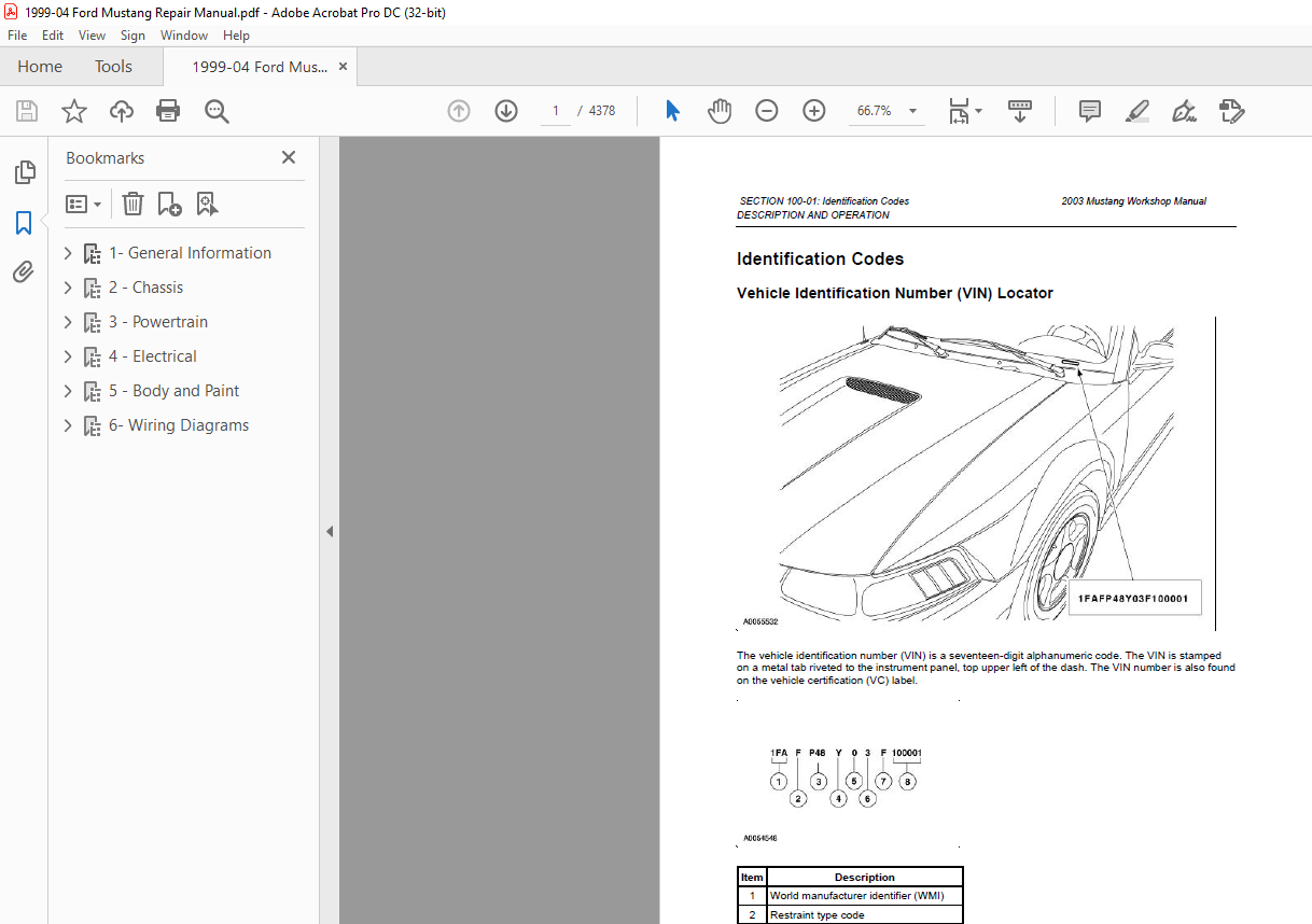
Powertrain calibration information is printed in the lower right corner of the Vehicle Certification Label.
Only the base calibration information is printed. Revision levels will not appear, however, this
information can be found in the On Line Automotive Service Information System (OASIS).
- For the current model year, Ford Motor Company is using three different protocols which describe powertrain
base calibration. These protocols are designed to provide worldwide standardization for vehicle
calibration. - If the electronic calibration strategy has been used since 1998 and carried into the current
model year, protocol 1 will be used. Refer to Protocol 1 below. If the electronic calibration strategy has
been used since 1999 and is carried into the current model year, protocol 2 will be used. Refer to
Protocol 2 below. For new electronic calibration strategies introduced since the 2000 model year, use
protocol 3. Refer to Protocol 3 below.
TABLE OF CONTENTS:
2003 Ford Mustang Workshop Manual – PDF DOWNLOAD
1- General Information 1
GROUP 00 Service Information 1
SECTION 100-01- Identification Codes – DESCRIPTION AND OPERATION 1
SECTION 100-02 Jacking and Lifting – DESCRIPTION AND OPERATION 17
SECTION 100-03 Maintenance Schedule – DESCRIPTION AND OPERATION 22
SECTION 100-04 Noise, Vibration and Harshness 33
DESCRIPTION AND OPERATION 33
DIAGNOSIS AND TESTING 48
GENERAL PROCEDURES 118
2 – Chassis 126
04 – Suspension 126
SECTION 204-00 Suspension System – General Information 126
SPECIFICATIONS 126
DESCRIPTION AND OPERATION 128
DIAGNOSIS AND TESTING 134
GENERAL PROCEDURES 140
Wheel Bearing Inspection 140
Camber and Caster Adjustment—Front 141
Camber Adjustment —Rear 145
Toe Adjustment—Front 147
Toe Adjustment —Rear 150
SECTION 204-01 Front Suspension 152
SPECIFICATIONS 152
REMOVAL AND INSTALLATION 153
Wheel Studs 153
Wheel Hub and Bearing 155
Arm —Lower 157
Bar—Stabilizer 159
Link —Stabilizer Bar 162
Bushing —Stabilizer Bar 164
Spindle 167
Shock Absorber 172
Spring 177
SECTION 204-02 Rear Suspension 185
SPECIFICATIONS 185
DESCRIPTION AND OPERATION 187
REMOVAL AND INSTALLATION 189
Wheel Hub—Cobra 189
Wheel Studs 195
Upper Arm 197
Upper Arm —Cobra 201
Lower Arm 206
Stabilizer Bar 208
Stabilizer Bar—Cobra 211
Link —Stabilizer Bar 214
Wheel Knuckle—Cobra 216
Toe Link—Cobra 225
Spring—Coil 229
Spring —Cobra 234
Shock Absorber 243
Damper 246
SECTION 204-04 Wheels and Tires 249
SPECIFICATIONS 249
DESCRIPTION AND OPERATION 251
DIAGNOSIS AND TESTING 254
GENERAL PROCEDURES 258
REMOVAL AND INSTALLATION 260
05 – Driveline 263
SECTION 205-00 Driveline System —General Information 263
SPECIFICATIONS 263
DIAGNOSIS AND TESTING 265
GENERAL PROCEDURES 284
SECTION 205-01 Driveshaft 288
SPECIFICATIONS 288
DESCRIPTION AND OPERATION 289
REMOVAL AND INSTALLATION 293
DISASSEMBLY AND ASSEMBLY 298
SECTION 205-02A Rear Drive Axle-Differential — Ford 7 5-Inch Ring Gear 306
SPECIFICATIONS 306
DESCRIPTION AND OPERATION 308
IN-VEHICLE REPAIR 311
Axle Shaft 311
Rear Wheel Bearing and Axle Shaft Oil Seal 315
Drive Pinion Flange and Drive Pinion Seal 318
Differential Housing Cover 323
Axle Housing Bushing 326
Drive Pinion 328
Differential Case 341
REMOVAL AND INSTALLATION 354
DISASSEMBLY AND ASSEMBLY 359
SECTION 205-02B Rear Drive Axle-Differential — Ford 8 8-Inch Ring Gear 365
SPECIFICATIONS 365
DESCRIPTION AND OPERATION 367
IN-VEHICLE REPAIR 370
Axle Shaft 370
Rear Wheel Bearing and Axle Shaft Oil Seal 374
Differential Housing Cover 377
Axle Housing Bushing 380
Drive Pinion 382
Differential Case 395
REMOVAL AND INSTALLATION 408
DISASSEMBLY AND ASSEMBLY 414
SECTION 205-02C Rear Drive Axle Differential — Ford 8 8-Inch IRS 429
SPECIFICATIONS 429
DESCRIPTION AND OPERATION 431
IN-VEHICLE REPAIR 434
Stub Shaft Pilot Bearing and Seal 434
Drive Pinion Flange 438
Pinion Seal 443
REMOVAL AND INSTALLATION 445
DISASSEMBLY AND ASSEMBLY 459
SECTION 205-05 Rear Drive Halfshafts 494
SPECIFICATIONS 494
DESCRIPTION AND OPERATION 495
REMOVAL AND INSTALLATION 498
DISASSEMBLY AND ASSEMBLY 507
06 – Brake System 510
SECTION 206-00 Brake System – General Information 510
SPECIFICATIONS 510
DESCRIPTION AND OPERATION 511
DIAGNOSIS AND TESTING 513
GENERAL PROCEDURES 528
Bleeding —Components 528
Bleeding —System 534
Hydraulic Leak Check 538
Runout Check —Brake Disc and Hub 539
SECTION 206-03 Front Disc Brake 542
SPECIFICATIONS 542
DESCRIPTION AND OPERATION 543
REMOVAL AND INSTALLATION 546
Pads 546
Brake Pads —Cobra 553
Caliper 557
Brake Caliper—Cobra 561
Brake Caliper Anchor Plate —Cobra 564
Brake Caliper Anchor Plate 566
Disc 568
Shield 570
DISASSEMBLY AND ASSEMBLY 572
SECTION 206-04 Rear Disc Brake 577
SPECIFICATIONS 577
DESCRIPTION AND OPERATION 578
REMOVAL AND INSTALLATION 580
DISASSEMBLY AND ASSEMBLY 592
SECTION 206-05 Parking Brake and Actuation 596
SPECIFICATIONS 596
DESCRIPTION AND OPERATION 597
DIAGNOSIS AND TESTING 599
GENERAL PROCEDURES 602
REMOVAL AND INSTALLATION 604
SECTION 206-06 Hydraulic Brake Actuation 614
SPECIFICATIONS 614
DESCRIPTION AND OPERATION 615
REMOVAL AND INSTALLATION 618
SECTION 206-07 Power Brake Actuation 630
SPECIFICATIONS 630
DESCRIPTION AND OPERATION 631
GENERAL PROCEDURES 635
REMOVAL AND INSTALLATION 637
SECTION 206-09A; Anti-Lock Control — Rear 645
SPECIFICATIONS 645
DESCRIPTION AND OPERATION 646
DIAGNOSIS AND TESTING 647
REMOVAL AND INSTALLATION 663
Sensor Indicator —Rear 663
Hydraulic Control Unit 666
Module 669
Sensor—Front 671
Sensor—Rear 674
SECTION 206-09B Anti-LocK Control — Traction Control 676
SPECIFICATIONS 676
DESCRIPTION AND OPERATION 677
DIAGNOSIS AND TESTING 678
REMOVAL AND INSTALLATION 698
Sensor Indicator —Rear 698
Hydraulic Control Unit 701
Module 704
Sensor—Front 706
Sensor—Rear 709
Switch —Traction Control 711
11 – Steering System 713
SECTION 211-00 Steering System – General Information 713
SPECIFICATIONS 713
DESCRIPTION AND OPERATION 715
DIAGNOSIS AND TESTING 718
GENERAL PROCEDURES 729
System Flushing —Сll Power Steering Pump 729
System Flushing —Clll Power Steering Pump 731
Purging —Сll Power Steering Pump 733
Purging —Clll Power Steering Pump 736
Fill 739
SECTION 211-02 Power Steering 741
SPECIFICATIONS 741
DESCRIPTION AND OPERATION 743
REMOVAL AND INSTALLATION 749
Reservoir—Clll Pump 749
Pump —Сll 751
Pump —Clll 754
Pulley—Cll Pump 757
Pulley— Clll Pump 759
Hose 761
Cooler—Fluid 763
Gear 765
DISASSEMBLY AND ASSEMBLY 769
SECTION 211-04 Steering Column 775
SPECIFICATIONS 775
DESCRIPTION AND OPERATION 776
GENERAL PROCEDURES 780
REMOVAL AND INSTALLATION 786
Ignition Switch Lock Cylinder—Functional 786
Ignition Switch Lock Cylinder—Non-Functional 788
Wheel 791
Column 793
Steering Column Shaft 797
Coupling 799
DISASSEMBLY AND ASSEMBLY 801
SECTION 211-05 Steering Column Switches 819
SPECIFICATIONS 819
DESCRIPTION AND OPERATION 820
DIAGNOSIS AND TESTING 821
REMOVAL AND INSTALLATION 829
3 – Powertrain 836
03 – Engine 836
SECTION 303-00 Engine System – General Information 836
SPECIFICATIONS 836
DESCRIPTION AND OPERATION 837
DIAGNOSIS AND TESTING 838
GENERAL PROCEDURES 855
Sprockets 855
Rocker Arms —Cleaning 856
Rocker Arms —Inspection 857
Push Rods —Cleaning 858
Push Rods—Inspection 859
Camshaft Journal —Diameter 860
Camshaft Journal —Clearance, Push Rod Engines, Micrometer Method 861
Camshaft Journal—Clearance, Plastigage Method 863
Camshaft End Play —Push Rod Engines 865
Camshaft End Play —OHC Engines 867
Camshaft—Lobe Surface 869
Camshaft Lobe Lift 870
Camshaft Runout 871
Crankshaft Main Bearing Journal —Diameter 873
Crankshaft Main Bearing Journal —Taper 874
Crankshaft Main Bearing Journal —Clearance 875
Crankshaft End Play 877
Crankshaft Runout 879
Crankshaft—Connecting RodJournal Taper, Out of Round 881
Cylinder Bore —Taper 882
Cylinder Bore —Out-of-Round 883
Piston Inspection 884
Piston —Pin to Bore Diameter 886
Piston —Diameter 888
Piston —to Cylinder Bore Clearance 889
Piston—Selection 890
Piston —Ring End Gap 892
Piston —Ring-to-Groove Clearance 894
Piston —Pin Diameter 896
Connecting Rod —Cleaning 897
Connecting Rod —Large End Bore 898
Connecting Rod —Bushing Diameter 899
Connecting Rod —Bend 900
Connecting Rod —Twist 901
Connecting Rod —Piston Pin Side Clearance 902
Connecting Rod —Bearing Journal Clearance 903
Connecting Rod —Side Clearance 905
Roller Follower—Inspection 906
Valve Tappet—Inspection 908
Valve —Stem Diameter 910
Valve Stem to Valve Guide Clearance 911
Valve—Inspection 913
Valve —Guide Inner Diameter 914
Valve —Guide Reaming 915
Valve —Spring Installed Length 916
Valve —Spring Free Length 917
Valve—Spring Squareness 918
Valve Spring Strength 919
Valve —Seat Inspection 921
Valve—Seat Width 922
Valve —Seat Runout 923
Cylinder Head —Distortion 924
Cylinder Bore —Cleaning 925
Cylinder Block Core Plug Replacement 926
Spark Plug Hole Thread Repair 928
Spark Plug —Inspection 929
Exhaust Manifold —Inspection 932
Bearing —Inspection 933
SECTION 303-01A Engine — 3 8L 935
SPECIFICATIONS 935
DESCRIPTION AND OPERATION 941
DIAGNOSIS AND TESTING 950
IN-VEHICLE REPAIR 951
Upper Intake Manifold 951
Lower Intake Manifold 959
Valve Cover —LH 968
Valve Cover RH 970
Crankshaft Pulley 973
Crankshaft Front Seal 976
Engine Front Cover 978
Rocker Arm 987
Push Rod 989
Valve Springs 991
Valve Tappets 994
Camshaft 996
Engine Dynamic Balance Shaft 999
Timing Chain 1002
Exhaust Manifold —LH 1007
Exhaust Manifold RH 1010
Cylinder Head LH 1013
Cylinder Head RH 1019
Oil Level Indicator and Tube 1024
Oil Pan 1026
Oil Pan Baffle 1038
Flywheel 1039
Oil Pump Screen and Pickup Tube 1041
Flexplate 1043
Crankshaft Rear Seal 1044
Engine Support Insulators 1047
REMOVAL 1055
DISASSEMBLY 1066
DISASSEMBLY AND ASSEMBLY OF SUBASSEMBLIES 1087
ASSEMBLY 1092
INSTALLATION 1120
SECTION 303-01B Engine — 4 6L(2V) 1130
SPECIFICATIONS 1130
DESCRIPTION AND OPERATION 1136
DIAGNOSIS AND TESTING 1145
IN-VEHICLE REPAIR 1146
Intake Manifold 1146
Valve Cover RH 1166
Valve Cover LH 1169
Crankshaft Pulley 1172
Crankshaft Front Oil Seal 1175
Engine Front Cover 1178
Timing Drive Components 1187
Valve Seals 1200
Hydraulic Lash Adjuster 1202
Camshaft Roller Follower 1203
Camshaft 1206
Exhaust Manifold RH 1208
Exhaust Manifold LH 1211
Oil Filter Adapter 1214
Oil Level Indicator and Tube 1217
Oil Pan 1219
Flywheel 1228
Flexplate 1230
Crankshaft Rear Oil Seal 1232
Engine Mount RH 1235
Engine Mount LH 1238
REMOVAL 1241
Cylinder Heads 1241
Engine 1262
DISASSEMBLY 1274
DISASSEMBLY AND ASSEMBLY OF SUBASSEMBLIES 1298
ASSEMBLY 1305
INSTALLATION 1341
Cylinder Heads 1341
Engine 1366
SECTION 303-01C Engine — Cobra 4 6L (4V) 1379
SPECIFICATIONS 1379
DESCRIPTION AND OPERATION 1385
DIAGNOSIS AND TESTING 1401
IN-VEHICLE REPAIR 1402
Lower Intake Manifold 1402
Valve Cover RH 1409
Valve Cover LH 1414
Crankshaft Pulley 1420
Crankshaft Pulley —Auxiliary 1423
Crankshaft Front Seal 1427
Engine Front Cover 1430
Timing Drive Components 1445
Hydraulic Lash Adjusters 1452
Camshaft Roller Follower 1453
Camshaft 1455
Exhaust Manifold RH 1462
Exhaust Manifold LH 1464
Oil Filter Adapter 1467
Oil Level Indicator and Tube 1470
Oil Pan 1472
Flywheel 1483
Crankshaft Rear Seal with Retainer Plate 1484
Engine Mount RH 1487
Engine Mount LH 1490
REMOVAL 1493
DISASSEMBLY 1510
DISASSEMBLY AND ASSEMBLY OF SUBASSEMBLIES 1533
Cylinder Head 1533
Piston 1544
Intake Manifold Assembly 1547
ASSEMBLY 1550
INSTALLATION 1585
SECTION 303-01D Engine — Mach 14 6L(4V 1602
SPECIFICATIONS 1602
DESCRIPTION AND OPERATION 1608
DIAGNOSIS AND TESTING 1623
IN-VEHICLE REPAIR 1624
Intake Manifold —Upper 1624
Intake Manifold —Lower 1631
Valve Cover RH 1635
Valve Cover LH 1644
Crankshaft Pulley 1652
Crankshaft Front Oil Seal 1655
Engine Front Cover 1658
Timing Drive Components 1679
Valve —Springs, Retainer and Valve Stem Seal 1686
Hydraulic Lash Adjusters 1691
Roller Followers 1692
Camshaft 1694
Exhaust Manifold RH 1701
Exhaust Manifold LH 1703
Oil Filter Adapter 1706
Oil Level Indicator and Tube 1708
Oil Pan 1710
Flexplate 1721
Flywheel 1723
Crankshaft Rear Oil Seal 1724
Engine Mount 1727
REMOVAL 1737
DISASSEMBLY 1756
DISASSEMBLY AND ASSEMBLY OF SUBASSEMBLIES 1777
ASSEMBLY 1791
INSTALLATION 1821
SECTION 303-03A Engine Cooling 1839
SPECIFICATIONS 1839
DESCRIPTION AND OPERATION 1841
DIAGNOSIS AND TESTING 1844
GENERAL PROCEDURES 1854
Cooling System Draining, Filling and Bleeding 1854
Engine and Radiator Flushing 1861
Heater Core Backflushing 1863
REMOVAL AND INSTALLATION 1865
Thermostat —3 8L 1865
Thermostat —4 6L(2V) 1868
Thermostat —4 6L(4V) 1870
Bypass Tube —3 8L 1872
Bypass Tube —Cobra 1875
Bypass Tube —Mach I 1877
Water Pump —3 8L 1880
Water Pump —4 6L(2V) and 4 6L(4V) 1883
Radiator 1887
Cooling Fan Motor and Shroud 1891
Water Bypass Hose —3 8L 1893
Degas Bottle —4 6L(2V) and 4 6L(4V) 1894
SECTION 303-03B Supercharger Cooling 1896
SPECIFICATIONS 1896
DESCRIPTION AND OPERATION 1898
DIAGNOSIS AND TESTING 1900
GENERAL PROCEDURES 1907
REMOVAL AND INSTALLATION 1911
SECTION 303-04A Fuel Charging and Controls — 3 8L 1917
SPECIFICATIONS 1917
DESCRIPTION AND OPERATION 1918
DIAGNOSIS AND TESTING 1920
GENERAL PROCEDURES 1921
REMOVAL AND INSTALLATION 1922
SECTION 303-04B Fuel Charging and Controls — 4 6L (2V) 1933
SPECIFICATIONS 1933
DESCRIPTION AND OPERATION 1934
DIAGNOSIS AND TESTING 1937
GENERAL PROCEDURES 1938
REMOVAL AND INSTALLATION 1939
SECTION 303-04C Fuel Charging and Controls — Cobra 4 6L (4V) 1965
SPECIFICATIONS 1965
DESCRIPTION AND OPERATION 1966
DIAGNOSIS AND TESTING 1968
REMOVAL AND INSTALLATION 1969
SECTION 303-04D Fuel Charging and Controls — Mach 14 6L (4V 1982
SPECIFICATIONS 1982
DESCRIPTION AND OPERATION 1984
DIAGNOSIS AND TESTING 1987
GENERAL PROCEDURES 1988
REMOVAL AND INSTALLATION 1989
SECTION 303-05 Accessory Drive 2007
SPECIFICATIONS 2007
DESCRIPTION AND OPERATION 2008
DIAGNOSIS AND TESTING 2013
REMOVAL AND INSTALLATION 2017
Accessory Drive Belt —3 8L 2017
Accessory Drive Belt —4 6L (2V) and (4V) 2018
Supercharger Belt 2020
Accessory Drive Belt Tensioner —3 8L 2022
Accessory Drive Belt Tensioner —4 6L (2V) and (4V) 2023
Supercharger Belt Tensioner 2026
Accessory Drive Belt Idler Pulley —3 8L 2028
Accessory Drive Belt Idler Pulley —4 6L (2V) and (4V) 2029
Supercharger Belt Idler Pulley 2032
SECTION 303-06 Starting System 2034
SPECIFICATIONS 2034
DESCRIPTION AND OPERATION 2035
DIAGNOSIS AND TESTING 2037
GENERAL PROCEDURES 2048
REMOVAL AND INSTALLATION 2050
SECTION 303-07A Engine Ignition — 3 8L 2057
SPECIFICATIONS 2057
DESCRIPTION AND OPERATION 2058
DIAGNOSIS AND TESTING 2060
REMOVAL AND INSTALLATION 2061
SECTION 303-07B Engine Ignition — 4 6L (2V) 2070
SPECIFICATIONS 2070
DESCRIPTION AND OPERATION 2071
DIAGNOSIS AND TESTING 2073
REMOVAL AND INSTALLATION 2074
SECTION 303-07C Engine Ignition — 4 6L (4V) 2080
SPECIFICATIONS 2080
DESCRIPTION AND OPERATION 2081
DIAGNOSIS AND TESTING 2083
REMOVAL AND INSTALLATION 2084
SECTION 303-08 Engine Emission Control 2089
SPECIFICATIONS 2089
DESCRIPTION AND OPERATION 2090
DIAGNOSIS AND TESTING 2093
REMOVAL AND INSTALLATION 2094
Exhaust Gas Recirculation (EGR) Valve 2094
Exhaust Gas Recirculation (EGR) Valve —Cobra 2096
Exhaust Gas Recirculation (EGR) Valve —Mach I 2100
Exhaust Manifold to Exhaust Gas Recirculation (EGR) Valve Tube 2102
Exhaust Manifold to Exhaust Gas Recirculation (EGR) Valve Tube —Cobra 2104
Exhaust Manifold to Exhaust Gas Recirculation (EGR) Valve Tube —Mach I 2105
Differential Pressure Feedback Exhaust Gas Recirculation (EGR) System 2107
Exhaust Gas Recirculation (EGR) Vacuum Regulator Solenoid 2108
Positive Crankcase Ventilation (PCV) Hose 2109
SECTION 303-12 Intake Air Distribution and Filtering 2111
SPECIFICATIONS 2111
DESCRIPTION AND OPERATION 2112
DIAGNOSIS AND TESTING 2115
REMOVAL AND INSTALLATION 2116
Air Cleaner Outlet Pipe —3 8L 2116
Air Cleaner Outlet Pipe —4 6L (2V) 2117
Air Cleaner Outlet Pipe —4 6L (4V) 2119
Air Cleaner —3 8L 2121
Air Cleaner —4 6L (2V) and 4 6L (4V) 2123
Air Cleaner Element —3 8L 2125
Air Cleaner Element —4 6L (2V) 2127
Air Cleaner Element —4 6L (4V) 2129
Air Intake Scoop 2130
Air Intake Scoop Bracket 2132
Charge Air Cooler 2134
SECTION 303-13 Evaporative Emissions 2144
SPECIFICATIONS 2144
DESCRIPTION AND OPERATION 2145
DIAGNOSIS AND TESTING 2148
GENERAL PROCEDURES 2173
REMOVAL AND INSTALLATION 2179
Evaporative Emission Canister 2179
Evaporative Emission Canister Purge Valve 2182
Fuel Vapor Vent Valve 2185
Fuel Vapor Control Tube Assembly Valve 2186
Fuel Tank Pressure Sensor 2188
Evaporative Emission Test Port 2189
Evaporative Emission Canister Vent Solenoid 2191
SECTION 303-14 Electronic Engine Controls 2192
SPECIFICATIONS 2192
DESCRIPTION AND OPERATION 2194
DIAGNOSIS AND TESTING 2199
REMOVAL AND INSTALLATION 2200
Temperature and Manifold Absolute Pressure (T-MAP) Sensor —Cobra 2200
Camshaft Position (CMP) Sensor —3 8L 2202
Camshaft Position (CMP) Sensor —4 6L 2203
Intake Manifold Runner Control (IMRC) Actuator —3 8L 2205
Crankshaft Position (CKP) Sensor —3 8L 2207
Crankshaft Position (CKP) Sensor —4 6L 2208
Powertrain Control Module (PCM) 2209
Throttle Position (TP) Sensor 2212
Throttle Position (TP) Sensor —Cobra 2214
Throttle Position (TP) Sensor —Mach I 2216
Idle Air Control (IAC) Valve —3 8L 2218
Idle Air Control (IAC) Valve —4 6L (2V) 2220
Idle Air Control (IAC) Valve —Cobra 2222
Idle Air Control (IAC) Valve —Mach I 2224
Cylinder Head Temperature (CHT) Sensor —3 8L 2226
Engine Coolant Temperature (ECT) Sensor —4 6L (2V) 2228
Engine Coolant Temperature (ECT) Sensor —Cobra 2230
Engine Coolant Temperature (ECT) Sensor —Mach I 2232
Mass Air Flow (MAF) Sensor —3 8L 2234
Mass Air Flow (MAF) Sensor —4 6L (2V) 2236
Mass Air Flow (MAF) Sensor —Cobra 2238
Mass Air Flow (MAF) Sensor —Mach I 2241
Heated Oxygen Sensor (HO2S) 2243
Catalyst Monitor Sensor 2245
Clutch Pedal Position (CPP) Switch 2247
Fuel Pressure Sensor 2249
Supercharger Bypass Vacuum Solenoid 2251
Supercharger Bypass Vacuum Solenoid —Actuator 2252
07 – Automatic Transmission 2258
SECTION 307-01 Automatic Transaxle- Transmission 2258
SPECIFICATIONS 2258
DESCRIPTION AND OPERATION 2264
Transmission Description 2264
Identification Tags 2265
Range Selection 2266
Shift Patterns 2268
Disassembled Views 2269
Bushings, Bearing and Thrust Washer Locator 2277
Seals, Rings and Gasket Locator 2279
Main Components and Functions 2282
Torque Converter 2284
Geartrain 2286
Apply Components 2288
Hydraulic System 2293
Transmission Electronic Control System 2297
DIAGNOSIS AND TESTING 2301
Diagnostic Strategy 2301
Diagnostic Flow Chart 2303
Preliminary Inspection 2305
Road Testing Vehicle 2308
Shift Point Road Test 2309
Torque Converter Diagnosis 2312
Visual Inspection 2316
Diagnostics 2318
Output State Control (OSC) Mode 2321
Transmission Drive Cycle Test 2330
Diagnostic Trouble Code Charts 2332
Transmission Connector Layouts 2340
Pinpoint Tests — OSC Equipped Vehicles 2344
Special Testing Procedures 2366
Leakage Inspection 2373
Transmission Fluid Cooler 2378
Diagnosis By Symptom 2380
GENERAL PROCEDURES 2411
IN-VEHICLE REPAIR 2419
Fluid Pan, Gasket and Filter 2419
Transmission Filler Tube 2424
Main Control Valve Body 2426
Extension Housing Seal and Gasket 2433
Electronic Pressure Control (EPC) Solenoid 2438
Manual Control Lever Shaft and Seal 2441
Digital Transmission Range (TR) Sensor 2447
Reverse Servo Assembly 2451
Overdrive Servo 2456
1-2 Accumulator 2458
2-3 Accumulator 2460
Transmission Support Crossmember 2462
REMOVAL 2464
DISASSEMBLY 2471
DISASSEMBLY AND ASSEMBLY OF SUBASSEMBLIES 2487
Main Control Valve Body 2487
Pump and Intermediate Clutch Piston 2495
Intermediate One-Way Clutch 2502
Reverse Clutch 2504
Forward Clutch Cylinder 2513
Planetary Gear Support Assembly and Planetary One-Way Clutch 2522
Reverse Sun Gear 2524
Output Shaft and Direct Clutch Cylinder 2526
Torque Converter 2537
Torque Converter Cleaning And Inspection 2538
Torque Converter Flushing 2540
Torque Converter Leak Check 2541
Torque Converter Impeller to Pump Stator Interference Check 2544
Torque Converter End Play Check 2546
Torque Converter One-Way Clutch Check 2548
Torque Converter Turbine to Pump Stator Interference Check 2550
ASSEMBLY 2552
INSTALLATION 2577
SECTION 307-02 Transaxle- Transmission Cooling 2584
SPECIFICATIONS 2584
DESCRIPTION AND OPERATION 2585
DIAGNOSIS AND TESTING 2587
REMOVAL AND INSTALLATION 2589
SECTION 307-05 Automatic Transaxle- Transmission External Controls 2592
SPECIFICATIONS 2592
DESCRIPTION AND OPERATION 2593
DIAGNOSIS AND TESTING 2594
GENERAL PROCEDURES 2600
REMOVAL AND INSTALLATION 2602
Brake Shift Interlock Actuator 2602
Cable and Bracket 2607
Selector Lever 2610
Transmission Control Switch 2614
Bezel 2617
Bulb 2620
Knob 2622
08 – Manual Transmission Clutch and Transfer Case 2625
SECTION 308-00 Manual Transrnissi-Transaxle anc Clutch -General Information 2625
SPECIFICATIONS 2625
DESCRIPTION AND OPERATION 2626
DIAGNOSIS AND TESTING 2630
GENERAL PROCEDURES 2645
REMOVAL AND INSTALLATION 2653
SECTION 308-01 Clutch 2656
SPECIFICATIONS 2656
DESCRIPTION AND OPERATION 2658
DIAGNOSIS AND TESTING 2659
REMOVAL AND INSTALLATION 2660
SECTION 308-02 Clutch Controls 2671
SPECIFICATIONS 2671
DESCRIPTION AND OPERATION 2673
DIAGNOSIS AND TESTING 2675
REMOVAL AND INSTALLATION 2676
SECTION 308-03A Manual TransaxleTransmission — T5OD 2687
SPECIFICATIONS 2687
DESCRIPTION AND OPERATION 2689
DIAGNOSIS AND TESTING 2694
IN-VEHICLE REPAIR 2695
REMOVAL 2702
DISASSEMBLY 2708
DISASSEMBLY AND ASSEMBLY OF SUBASSEMBLIES 2719
Selector Plate 2719
Input Shaft and Bearing 2723
Output Shaft 2726
Countershaft Bearing 2736
Synchronizers 2739
ASSEMBLY 2741
INSTALLATION 2755
SECTION 308-03B Manual TransaxleTransmission — TR3650 2756
SPECIFICATIONS 2756
DESCRIPTION AND OPERATION 2758
DIAGNOSIS AND TESTING 2765
GENERAL PROCEDURES 2766
IN-VEHICLE REPAIR 2769
REMOVAL 2776
DISASSEMBLY 2781
DISASSEMBLY AND ASSEMBLY OF SUBASSEMBLIES 2796
Input Shaft and Bearing 2796
Output Shaft 2799
Countershaft Bearing 2816
Synchronizers 2818
Gearshift Rail Bushing 2820
Gearshift Rail and Fork 2822
ASSEMBLY 2824
INSTALLATION 2843
SECTION 308-03C Manual TransaxleTransmission — T56 2844
SPECIFICATIONS 2844
DESCRIPTION AND OPERATION 2846
DIAGNOSIS AND TESTING 2848
GENERAL PROCEDURES 2849
REMOVAL 2851
DISASSEMBLY 2856
DISASSEMBLY AND ASSEMBLY OF SUBASSEMBLIES 2869
Input Shaft and Bearing 2869
Output Shaft 2873
Countershaft 2885
Synchronizers 2893
Gearshift Rail and Fork 2895
Extension Housing 2898
Transmission Case 2904
ASSEMBLY 2908
INSTALLATION 2926
09 – Exhaust System – SECTION 309-00 Exhaust System 2931
SPECIFICATIONS 2931
DESCRIPTION AND OPERATION 2932
DIAGNOSIS AND TESTING 2935
REMOVAL AND INSTALLATION 2937
Muffler —3 8L 2937
Muffler —4 6L (2V) 2940
Muffler —4 6L (4V) 2943
Dual Converter Y-Pipe —3 8L 2946
Dual Converter H-Pipe —4 6L (2V and 4V) 2951
10 – Fuel System 2955
SECTION 310-00 Fuel System – General Information 2955
SPECIFICATIONS 2955
DESCRIPTION AND OPERATION 2956
DIAGNOSIS AND TESTING 2958
GENERAL PROCEDURES 2959
Pressure Relief 2959
Fuel Tank Draining 2961
Spring Lock Couplings 2963
Fuel Line Fittings —Push Connect 2966
Fittings —R-Clip 2969
Fittings —Vapor Tube 2972
SECTION 310-01 Fuel Tank and Lines 2974
SPECIFICATIONS 2974
DESCRIPTION AND OPERATION 2975
DIAGNOSIS AND TESTING 2976
REMOVAL AND INSTALLATION 2977
Fuel Tank 2977
Support Straps 2982
Fuel Pump Module 2984
Fuel Tank Filler Pipe 2986
Fuel Filter 2987
Inertia Fuel Shutoff (IFS) Switch 2989
SECTION 310-02 Acceleration Control 2990
DESCRIPTION AND OPERATION 2990
DIAGNOSIS AND TESTING 2992
REMOVAL AND INSTALLATION 2994
Accelerator Pedal and Shaft 2994
Accelerator Cable —3 8L 2996
Accelerator Cable —4 6L (2V) 2998
Accelerator Cable —Supercharged Engine 3000
Accelerator Cable Bracket —3 8L 3002
Accelerator Cable Bracket —4 6L (2V) 3004
Accelerator Cable Bracket —Supercharged Engine 3006
SPECIFICATIONS 3008
SECTION 310-03 Speed Control 3009
SPECIFICATIONS 3009
DESCRIPTION AND OPERATION 3010
DIAGNOSIS AND TESTING 3011
GENERAL PROCEDURES 3024
REMOVAL AND INSTALLATION 3025
Actuator Cable —Speed Control 3025
Actuator Cable —Speed Control-Cobra 3027
Actuator —Speed Control Servo 3029
Switch —Deactivator 3032
Switch —Speed Control Actuator 3034
4 – Electrical 3037
12 – Climate Control System 3037
SECTION 412-00 Climate Control System – General Information 3037
SPECIFICATIONS 3037
DESCRIPTION AND OPERATION 3039
DIAGNOSIS AND TESTING 3050
GENERAL PROCEDURES 3091
Air Conditioning (A-C) System Check — Retail Procedure 3091
Spring Lock Coupling 3093
Heater Hose Coupling 3099
Air Conditioning Line (Peanut) Fitting 3102
Refrigerant System Tests 3105
Air Conditioning (A-C) Clutch Air Gap Adjustment 3109
Manifold Gauge Set Connection 3110
Electronic Leak Detection 3113
Tracer Dye Leak Detection 3115
Air Conditioning (A-C) System Flushing 3117
Air Conditioning (A-C) System Recovery, Evacuation and Charging 3120
Refrigerant System Filtering Following Air Conditioning (A-C) Component Installation 3123
Refrigerant Oil Adding 3125
Inspection and Assembly Requirements —Following an AC Compressor Failure 3127
Refrigerant Identification Testing 3129
Contaminated Refrigerant Handling 3131
Vacuum Hose Repair —Mini-Tube 3133
SECTION 412-01 Air Distribution and Filtering 3135
SPECIFICATIONS 3135
DESCRIPTION AND OPERATION 3136
DIAGNOSIS AND TESTING 3139
REMOVAL AND INSTALLATION 3140
Register —LH 3140
Register —Center 3143
Nozzle —LH Demister and Hose 3144
Nozzle —RH Demister and Hose 3145
Duct —Floor 3146
Duct —Defroster 3147
Duct —RH Instrument Panel Register 3148
Plenum Chamber 3150
Door —Air Inlet Duct 3153
SECTION 412-02 Heating and Ventilation 3155
SPECIFICATIONS 3155
DESCRIPTION AND OPERATION 3156
DIAGNOSIS AND TESTING 3158
REMOVAL AND INSTALLATION 3159
DISASSEMBLY AND ASSEMBLY 3168
SECTION 412-03 Air Conditioning 3172
SPECIFICATIONS 3172
DESCRIPTION AND OPERATION 3174
DIAGNOSIS AND TESTING 3184
REMOVAL AND INSTALLATION 3185
Air Conditioning (AC) Compressor —3 8L 3185
Air Conditioning (AC) Compressor —4 6L 3189
Air Conditioning (AC) Compressor Bracket —3 8L 3192
Clutch And Clutch Field Coil 3193
Air Conditioning (AC) Compressor Shaft Seal 3198
Evaporator Core 3205
Suction Accumulator 3206
Air Conditioning (AC) Pressure Relief Valve —3 8L 3209
Air Conditioning (AC) Pressure Relief Valve —4 6L 3211
Condenser Core 3213
Compressor Manifold and Tube Assembly —3 8L 3218
Compressor Manifold and Tube Assembly —4 6L 3222
Suction Accumulator to Compressor Line —4 6L 3225
Compressor to Condenser Discharge Line —4 6L 3227
Condenser to Evaporator Line 3230
SECTION 412-04 Control Components 3233
DESCRIPTION AND OPERATION 3233
DIAGNOSIS AND TESTING 3237
REMOVAL AND INSTALLATION 3238
Control Assembly 3238
Switch 3242
Actuator —Temperature Control Cable 3244
Resistor 3245
Vacuum Control Motor —Air Inlet Duct Door 3247
Vacuum Control Motor —Air Damper Door 3249
Vacuum Control Motor —Windshield- Defroster Door 3250
Vacuum Reservoir Tank 3251
13 – Instrumentation and Warning Systems 3252
SECTION 413-00 Instrument Cluster and Panel Illumination 3252
DESCRIPTION AND OPERATION 3252
DIAGNOSIS AND TESTING 3253
REMOVAL AND INSTALLATION 3258
SECTION 413-01 Instrument Cluster 3259
DESCRIPTION AND OPERATION 3259
DIAGNOSIS AND TESTING 3263
REMOVAL AND INSTALLATION 3304
SECTION 413-06 Horn 3309
SPECIFICATIONS 3309
DESCRIPTION AND OPERATION 3310
DIAGNOSIS AND TESTING 3311
REMOVAL AND INSTALLATION 3316
SECTION 413-09 Warning Devices 3318
DESCRIPTION AND OPERATION 3318
DIAGNOSIS AND TESTING 3319
GENERAL PROCEDURES 3339
REMOVAL AND INSTALLATION 3341
14 – Battery and Charging System 3345
SECTION 414-00 Charging System – General Information 3345
SPECIFICATIONS 3345
DESCRIPTION AND OPERATION 3346
DIAGNOSIS AND TESTING 3348
SECTION 414-01 Battery, Mounting and Cables 3362
SPECIFICATIONS 3362
DESCRIPTION AND OPERATION 3364
DIAGNOSIS AND TESTING 3366
GENERAL PROCEDURES 3368
REMOVAL AND INSTALLATION 3370
Battery 3370
Battery Tray 3373
Battery Cables 3375
SECTION 414-02 Generator and Regulator 3381
SPECIFICATIONS 3381
DESCRIPTION AND OPERATION 3383
DIAGNOSIS AND TESTING 3384
REMOVAL AND INSTALLATION 3385
15 – Audio Systems 3391
SECTION 415-00 Entertainment System – General Information- DIAGNOSIS AND TESTING 3391
SECTION 415-01 Audio Unit 3415
SPECIFICATIONS 3415
DESCRIPTION AND OPERATION 3416
DIAGNOSIS AND TESTING 3417
REMOVAL AND INSTALLATION 3418
Audio Unit 3418
Subwoofer Amplifier —Convertible 3419
Subwoofer Amplifier —Coupe 3421
Subwoofer Amplifier —Mach 1000 3422
SECTION 415-02 Antenna 3424
SPECIFICATIONS 3424
DESCRIPTION AND OPERATION 3425
DIAGNOSIS AND TESTING 3426
REMOVAL AND INSTALLATION 3427
SECTION 415-03 Speakers 3431
SPECIFICATIONS 3431
DESCRIPTION AND OPERATION 3432
DIAGNOSIS AND TESTING 3433
REMOVAL AND INSTALLATION 3434
Door Speaker —Upper 3434
Door Speaker —Lower 3436
Speaker —Package Tray (Coupe) 3437
Subwoofer Speaker —Coupe 3438
Subwoofer Speaker —Convertible 3440
Quarter Panel Speaker 3442
17 – Lighting 3443
SECTION 417-01 Exterior Lighting 3443
SPECIFICATIONS 3443
DESCRIPTION AND OPERATION 3444
DIAGNOSIS AND TESTING 3445
Headlamps 3445
Stoplamps 3453
Turn Signal and Hazard Lamps 3458
Parking, Rear and License Lamps 3462
Fog Lamps 3465
Reversing Lamps 3471
GENERAL PROCEDURES 3475
REMOVAL AND INSTALLATION 3479
Bulb —Headlamp 3479
Lamp Assembly —Headlamp 3481
Lamp Assembly —Fog Lamp (GT) 3483
Lamp Assembly —Fog Lamp (Cobra) 3485
Lamp Assembly —Rear 3486
Lamp Switch —Headlamp 3488
Lamp Switch —Brake Pedal Position (BPP) 3490
SECTION 417-02 Interior Lighting 3492
DESCRIPTION AND OPERATION 3492
DIAGNOSIS AND TESTING 3493
REMOVAL AND INSTALLATION 3509
SECTION 417-04 Daytime Running Lamps (DRL) 3511
SPECIFICATIONS 3511
DESCRIPTION AND OPERATION 3512
DIAGNOSIS AND TESTING 3513
REMOVAL AND INSTALLATION 3519
18 – Electrical Distribution 3521
SECTION 418-00 Module Communications Network 3521
SPECIFICATIONS 3521
DESCRIPTION AND OPERATION 3522
DIAGNOSIS AND TESTING 3524
GENERAL PROCEDURES 3545
SECTION 418-01 Module Configuration- DIAGNOSIS AND TESTING 3548
19 – Electronic Feature Group 3551
SECTION 419-01 Anti-Theft — PATS 3551
SPECIFICATIONS 3551
DESCRIPTION AND OPERATION 3552
DIAGNOSIS AND TESTING 3554
GENERAL PROCEDURES 3572
Key Programming —Erase All Key Codes and Program Two Keys 3572
Key Programming —Program a Key Using Two Programmed Keys 3574
Key Programming —Enable-Disable Spare Key Programming 3576
Key Programming —Additional Key With One Programmed Key 3578
Security Access —Procedure 3580
REMOVAL AND INSTALLATION 3582
SECTION 419-10 Multifunction Electronic Modules 3586
SPECIFICATIONS 3586
DESCRIPTION AND OPERATION 3587
DIAGNOSIS AND TESTING 3588
REMOVAL AND INSTALLATION 3589
5 – Body and Paint 3591
01 – Body 3591
SECTION 501-00 Body System – General Information 3591
SPECIFICATIONS 3591
DESCRIPTION AND OPERATION 3592
DIAGNOSIS AND TESTING 3596
SECTION 501-02 Front End Body Panels 3598
SPECIFICATIONS 3598
DESCRIPTION AND OPERATION 3599
REMOVAL AND INSTALLATION 3600
SECTION 501-03 Body Closures 3604
SPECIFICATIONS 3604
DESCRIPTION AND OPERATION 3606
GENERAL PROCEDURES 3607
REMOVAL AND INSTALLATION 3614
SECTION 501-05 Interior Trim and Ornamentation 3619
SPECIFICATIONS 3619
DESCRIPTION AND OPERATION 3620
REMOVAL AND INSTALLATION 3621
Trim Panel —Door 3621
Trim Panel —Quarter, Coupe 3624
Trim Panel —Quarter, Convertible 3626
Trim Panel —Upper Quarter 3629
Trim Panel —Package Tray 3632
Headliner 3635
SECTION 501-08 Exterior Trim and Ornamentation 3638
SPECIFICATIONS 3638
DESCRIPTION AND OPERATION 3639
REMOVAL AND INSTALLATION 3640
SECTION 501-09 Rear View Mirrors 3648
SPECIFICATIONS 3648
DESCRIPTION AND OPERATION 3649
DIAGNOSIS AND TESTING 3650
REMOVAL AND INSTALLATION 3658
SECTION 501-10 Seating 3663
SPECIFICATIONS 3663
DESCRIPTION AND OPERATION 3664
DIAGNOSIS AND TESTING 3667
REMOVAL AND INSTALLATION 3682
Switch —Seat Regulator Control 3682
Lumbar Control Switch 3684
Front Seat Backrest 3687
Lumbar Assembly 3689
Seat —Front Power 3692
Seat Track 3694
Lumbar Motor 3696
Latch —Front Seat Backrest 3699
DISASSEMBLY AND ASSEMBLY 3702
Front Seat Cushion 3702
Front Seat Backrest 3706
SECTION 501-11 Glass, Frames and Mechanisms 3710
SPECIFICATIONS 3710
DESCRIPTION AND OPERATION 3712
DIAGNOSIS AND TESTING 3714
GENERAL PROCEDURES 3746
Heated Window Grid Wire Repair 3746
Lead Terminal Repair 3749
Door Window Glass Adjustment —Height Stop Adjustment 3752
Door Window Glass Adjustment —Stabilizer 3754
Rear Quarter Window Glass Adjustment —Convertible 3756
REMOVAL AND INSTALLATION 3757
Switch —Window Regulator Control 3757
Rear Window Defrost Switch 3759
Rear Window Glass 3760
Window Glass —Door 3764
Window Glass —Quarter 3766
Window Glass —Quarter, Convertible 3768
Motor —Window Regulator 3771
Motor —Window Regulator, Quarter 3773
Window Regulator —Power 3775
Window Regulator —Quarter 3777
Windshield Glass 3779
Door Glass Run Retainer 3789
SECTION 501-12 Instrument Panel and Console 3790
SPECIFICATIONS 3790
DESCRIPTION AND OPERATION 3791
REMOVAL AND INSTALLATION 3793
SECTION 501-14A Handles, Locks, Latches and Mechanisms 3812
SPECIFICATIONS 3812
DESCRIPTION AND OPERATION 3814
DIAGNOSIS AND TESTING 3816
REMOVAL AND INSTALLATION 3817
Latch —Door 3817
Latch —Luggage Compartment Lid 3820
Handle —Exterior Door 3822
Handle —Interior Door 3824
Ignition Lock Cylinder —Functional 3826
Ignition Lock Cylinder —Non-Functional 3828
Lock Cylinder —Door 3831
Lock Cylinder —Luggage Compartment Lid 3833
Push Button Rod —Door 3835
Actuator —Door Lock 3836
Switch —Door Ajar Switch 3838
Switch —Door Lock 3839
SECTION 501-14B Keyless Entry-Computer Operated Locks 3841
DESCRIPTION AND OPERATION 3841
DIAGNOSIS AND TESTING 3842
GENERAL PROCEDURES 3863
REMOVAL AND INSTALLATION 3864
SECTION 501-16 Wipers and Washers 3866
SPECIFICATIONS 3866
DESCRIPTION AND OPERATION 3867
DIAGNOSIS AND TESTING 3868
GENERAL PROCEDURES 3888
REMOVAL AND INSTALLATION 3890
Pivot Arm 3890
Mounting Arm and Pivot Shaft 3891
Motor —Windshield Wiper 3894
Washer Pump 3897
Reservoir 3899
Module —Generic Electronic (GEM) 3901
Switch —Multi-Function 3902
SECTION 501-18 Convertible Top 3903
SPECIFICATIONS 3903
DESCRIPTION AND OPERATION 3905
DIAGNOSIS AND TESTING 3907
GENERAL PROCEDURES 3917
REMOVAL AND INSTALLATION 3926
Convertible Top Assembly —Side Rail, Folding Top 3926
Convertible Top Assembly —Rear Window Glass 3938
Convertible Top Material 3944
Stay Pad —Convertible Top 3957
Convertible Top Switch 3960
Hydraulic System, Lift Cylinder and Motor 3961
SECTION 501-19 Bumpers 3967
SPECIFICATIONS 3967
DESCRIPTION AND OPERATION 3968
REMOVAL AND INSTALLATION 3969
Front Bumper Cover 3969
Rear Bumper Cover 3972
Front Bumper 3974
Rear Bumper 3976
SECTION 501-20A Safety Belt System 3978
SPECIFICATIONS 3978
DESCRIPTION AND OPERATION 3979
DIAGNOSIS AND TESTING 3982
GENERAL PROCEDURES 3986
Safety Belt Cleaning 3986
Safety Belt Maintenance 3987
Safety Belt With Anchor Plate Thread Damage 3988
Replacement of the Weld Nut and Reinforcement 3989
Safety Belt Procedure After a Collision 3990
Safety Belt Tongue Rotated on Belt 3991
REMOVAL AND INSTALLATION 3993
Retractor —Front Seat Safety Belt, Coupe 3993
Retractor —Front Seat Safety Belt, Convertible 3997
Retractor —Rear Seat Safety Belt, Coupe 3999
Retractor —Rear Seat Safety Belt, Convertible 4002
Child Safety Seat Belt —Tether Anchor 4005
Safety Belt Buckle —Front Seat 4007
Safety Belt Buckle —Rear Seat 4009
Child Safety Seat Tether Anchor —LATCH 4011
SECTION 501-20B Supplemental Restraint System 4012
SPECIFICATIONS 4012
DESCRIPTION AND OPERATION 4013
DIAGNOSIS AND TESTING 4017
Air Bag Supplemental Restraint System (SRS) 4017
Diagnostic Instructions — Air Bag Supplemental Restraint System (SRS) 4023
Pinpoint Tests — Air Bag Supplemental Restraint System (SRS) 4028
GENERAL PROCEDURES 4074
Inspection and Repair After a Supplemental Restraint System (SRS) Deployment 4074
Air Bag Disposal —Deployed Air Bag 4076
Air Bag Disposal —Undeployed Inoperative 4077
Air Bag Disposal —Driver, Undeployed, Scrapped Vehicle 4079
Air Bag Disposal —Passenger, Undeployed, Scrapped Vehicle 4082
Supplemental Restraint System (SRS) Deactivation and Reactivation 4085
Weld Nut Repair —J Nut, Restraints Control Module (RCM) 4092
Weld Nut Repair —Missing Weld Nut, Restraints Control Module (RCM) 4094
Weld Nut Repair —Stripped Weld Nut, Restraints Control Module (RCM) 4096
REMOVAL AND INSTALLATION 4098
Restraints Control Module (RCM) 4098
Driver Air Bag Module 4102
Passenger Air Bag Module 4108
Clockspring 4112
02 – Frame and Mounting 4123
02 – Frame and Mounting – SECTION 502-00 Frame and Body Mounting 4123
SPECIFICATIONS 4123
DESCRIPTION AND OPERATION 4124
GENERAL PROCEDURES 4125
REMOVAL AND INSTALLATION 4129
Front Subframe —3 8L Engine 4129
Front Subframe —4 6L (2V) Engine 4134
Front Subframe —4 6L (4V) Engine 4138
Rear Subframe 4142
Subframe Support —Convertible 4144
6- Wiring Diagrams 4146
Using Wiring Diagrams 4146
2003 Ford Mustang 4155
AIR CONDITIONING 4155
ANTI-LOCK BRAKES 4157
ANTI-THEFT 4158
BODY CONTROL MODULES 4159
COMPUTER DATA LINES 4160
COOLING FAN 4161
CRUISE CONTROL 4164
DEFOGGERS 4165
ENGINE PERFORMANCE 4166
EXTERIOR LIGHTS 4177
GROUND DISTRIBUTION 4179
HEADLIGHTS 4181
HORN 4183
INSTRUMENT CLUSTER 4184
INTERIOR LIGHTS 4185
POWER DISTRIBUTION 4187
POWER DOOR LOCKS 4190
POWER MIRRORS 4191
POWER SEATS 4191
Fig 38: Power Seat CircuitPOWER TOP/SUNROOF 4194
POWER WINDOWS 4194
RADIO 4197
SHIFT INTERLOCK 4203
STARTING/CHARGING 4203
SUPPLEMENTAL RESTRAINTS 4206
TRANSMISSION 4206
TRUNK, TAILGATE, FUEL DOOR 4208
WARNING SYSTEMS 4209
WIPER/WASHER 4209
2003 Ford Mustang GT 4211
AIR CONDITIONING 4211
ANTI-LOCK BRAKES 4214
ANTI-THEFT 4215
BODY CONTROL MODULES 4215
COMPUTER DATA LINES 4216
COOLING FAN 4218
CRUISE CONTROL 4220
DEFOGGERS 4221
ENGINE PERFORMANCE 4222
EXTERIOR LIGHTS 4233
GROUND DISTRIBUTION 4236
HEADLIGHTS 4238
HORN 4239
INSTRUMENT CLUSTER 4240
INTERIOR LIGHTS 4241
POWER DISTRIBUTION 4243
POWER DOOR LOCKS 4246
POWER MIRRORS 4247
POWER SEATS 4248
POWER TOP/SUNROOF 4250
POWER WINDOWS 4251
RADIO 4252
SHIFT INTERLOCK 4259
STARTING/CHARGING 4260
SUPPLEMENTAL RESTRAINTS 4262
TRANSMISSION 4263
TRUNK, TAILGATE, FUEL DOOR 4264
WARNING SYSTEMS 4265
WIPER/WASHER 4265
2003 Ford Mustang Cobra 4267
AIR CONDITIONING 4267
ANTI-LOCK BRAKES 4270
ANTI-THEFT 4271
BODY CONTROL MODULES 4271
COMPUTER DATA LINES 4272
COOLING FAN 4274
CRUISE CONTROL 4276
DEFOGGERS 4277
ENGINE PERFORMANCE 4278
EXTERIOR LIGHTS 4290
GROUND DISTRIBUTION 4291
HEADLIGHTS 4294
HORN 4295
INSTRUMENT CLUSTER 4296
INTERIOR LIGHTS 4296
POWER DISTRIBUTION 4299
POWER DOOR LOCKS 4301
POWER MIRRORS 4302
POWER SEATS 4304
POWER TOP/SUNROOF 4306
POWER WINDOWS 4307
RADIO 4308
SHIFT INTERLOCK 4314
STARTING/CHARGING 4316
SUPPLEMENTAL RESTRAINTS 4318
TRANSMISSION 4319
TRUNK, TAILGATE, FUEL DOOR 4320
WARNING SYSTEMS 4321
WIPER/WASHER 4322
2003 Ford Mustang Mac 4323
AIR CONDITIONING 4323
ANTI-LOCK BRAKES 4326
ANTI-THEFT 4327
BODY CONTROL MODULES 4327
COMPUTER DATA LINES 4329
COOLING FAN 4330
CRUISE CONTROL 4332
DEFOGGERS 4333
ENGINE PERFORMANCE 4334
EXTERIOR LIGHTS 4345
GROUND DISTRIBUTION 4348
HEADLIGHTS 4349
HORN 4351
INSTRUMENT CLUSTER 4352
INTERIOR LIGHTS 4353
POWER DISTRIBUTION 4355
POWER DOOR LOCKS 4357
POWER MIRRORS 4359
POWER SEATS 4360
POWER TOP/SUNROOF 4362
POWER WINDOWS 4363
RADIO 4363
SHIFT INTERLOCK 4363
STARTING/CHARGING 4363
SUPPLEMENTAL RESTRAINTS 4363
TRANSMISSION 4363
TRUNK, TAILGATE, FUEL DOOR 4363
WARNING SYSTEMS 4363
WIPER/WASHER 4363
VIDEO PREVIEW OF THE MANUAL:
PLEASE NOTE:
- This is the SAME manual used by the dealers to troubleshoot any faults in your vehicle. This can be yours in 2 minutes after the payment is made.
- Contact us at [email protected] should you have any queries before your purchase or that you need any other service / repair / parts operators manual.
S.V


