2001 Jeep Wrangler TJ Chassis Service Manual – PDF DOWNLOAD
DESCRIPTION:
2001 Jeep Wrangler TJ Chassis Service Manual – PDF DOWNLOAD
INTRODUCTION:
The procedures contained in this manual include all the specifications, instructions, and graphics needed to diagnose Mark 20 Antilock Braking System (ABS) problems. The diagnostics in this manual are based on the failure condition or symptom being present at time of diagnosis. Follow the recommendations below when choosing your diagnostic path.
1. First make sure the DRBIIIt is communicating with the CAB. If the DRBIIIt displays a ‘‘No Response’’ condition, you must diagnose that first.
2. Read DTC’s (diagnostic trouble codes) with the DRBIIIt.
3. If no DTC’s are present, identify the customer complaint.
4. Once the DTC or customer complaint is identified, locate the matching test in the Table of Contents and begin to diagnose the symptom. All component location views are in Section 8.0. All connector pinouts are in Section 9.0. All schematics are in Section 10.0.
An * placed before the symptom description indicated a customer complaint.
- When repairs are required, refer to the appropriate service manual for the proper removal and repair procedure.Diagnostic procedures change every year. New diagnostic systems may be added; carryover systems may be enhanced.
- READ THIS MANUAL BEFORE TRYING TO DIAGNOSE A VEHICLE DIAGNOSTIC TROUBLE CODE. It is recommended that you review the entire manual to become familiar with all new and changed diagnostic procedures. After using this book, if you have any comments or recommendations, please fill out the form at the back of the book and mail it back to us.
TABLE OF CONTENTS:
2001 Jeep Wrangler TJ Chassis Service Manual – PDF DOWNLOAD
1 0 INTRODUCTION 1
1 1 SYSTEM COVERAGE 1
1 2 SIX-STEP TROUBLESHOOTING PROCEDURE 1
2 0 IDENTIFICATION OF SYSTEM 1
3 0 SYSTEM DESCRIPTION AND FUNCTIONAL OPERATION 1
3 1 TEVES ABS SYSTEM DESCRIPTION 1
3 1 1 PEDAL FEEL/VEHICLE CHARACTERISTICS 2
3 1 2 SYSTEM COMPONENTS 2
3 1 3 ABS AND BRAKE WARNING INDICATORS 2
3 1 4 CONTROLLER ANTILOCK BRAKE (CAB) 2
3 1 5 HYDRAULIC CONTROL UNIT 3
3 1 6 RELAYS/SWITCHES 3
3 1 7 SENSORS 3
3 2 DIAGNOSTIC TROUBLE CODES 4
3 2 1 SYSTEM INITIALIZATION 4
3 2 2 DIAGNOSTIC MODE 4
3 2 3 INTERMITTENT DIAGNOSTIC TROUBLE CODES 4
3 3 USING THE DRBIIIT 4
3 4 DRBIIIT ERROR MESSAGES 4
3 4 1 DRBIIIT DOES NOT POWER UP (BLANK SCREEN) 5
3 4 2 DISPLAY IS NOT VISIBLE 5
4 0 DISCLAIMERS, SAFETY WARNINGS 5
4 1 DISCLAIMERS 5
4 2 SAFETY 5
4 2 1 TECHNICIAN SAFETY INFORMATION 5
4 2 2 VEHICLE PREPARATION FOR TESTING 5
4 2 3 SERVICING SUB-ASSEMBLIES 5
4 2 4 DRBIIIT SAFETY INFORMATION 5
4 3 WARNING 6
4 3 1 VEHICLE DAMAGE WARNINGS 6
4 3 2 ROAD TESTING A COMPLAINT VEHICLE 6
4 4 DIAGNOSIS 6
5 0 REQUIRED TOOLS AND EQUIPMENT 7
6 0 GLOSSARY OF TERMS 7
7 0 DIAGNOSTIC INFORMATION AND PROCEDURES 9
BRAKES (CAB)
CAB POWER FEED CIRCUIT 10
CONTROLLER FAILURE 13
G-SWITCH NOT PROCESSABLE 15
LEFT FRONT SENSOR CIRCUIT FAILURE 19
LEFT REAR SENSOR CIRCUIT FAILURE 19
RIGHT FRONT SENSOR CIRCUIT FAILURE 19
RIGHT REAR SENSOR CIRCUIT FAILURE 19
LEFT FRONT SENSOR SIGNAL FAILURE 22
TABLE OF CONTENTS – Continued
LEFT REAR SENSOR SIGNAL FAILURE 22
RIGHT FRONT SENSOR SIGNAL FAILURE 22
RIGHT REAR SENSOR SIGNAL FAILURE 22
PUMP MOTOR NOT WORKING PROPERLY 26
SYSTEM OVERVOLTAGE 30
SYSTEM UNDERVOLTAGE 32
*ABS WARNING INDICATOR ALWAYS ON 34
*ABS WARNING INDICATOR INOPERATIVE 36
*BRAKE LAMP SWITCH 38
VERIFICATION TESTS
VERIFICATION TESTS 39
8 0 COMPONENT LOCATIONS 41
8 1 CONTROLLER ANTILOCK BRAKE 41
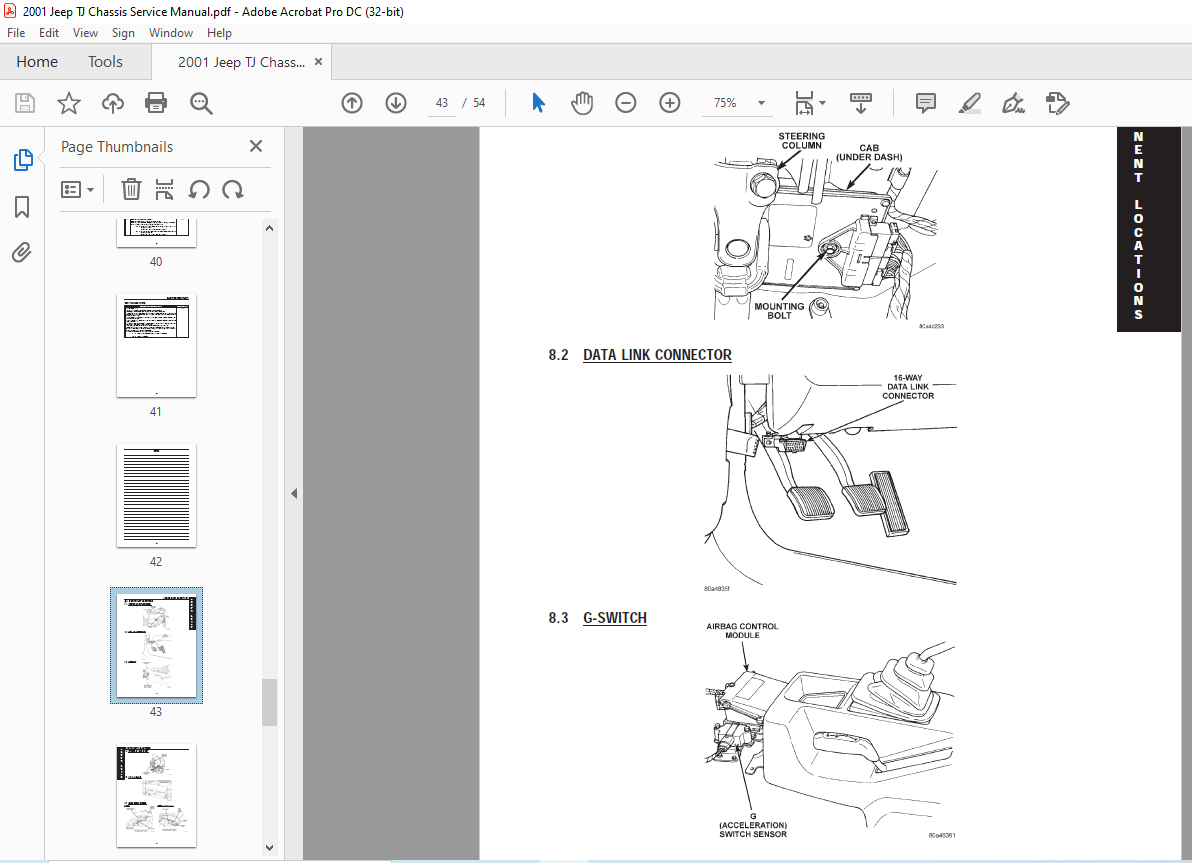
8 2 DATA LINK CONNECTOR 41
8 3 G-SWITCH 41
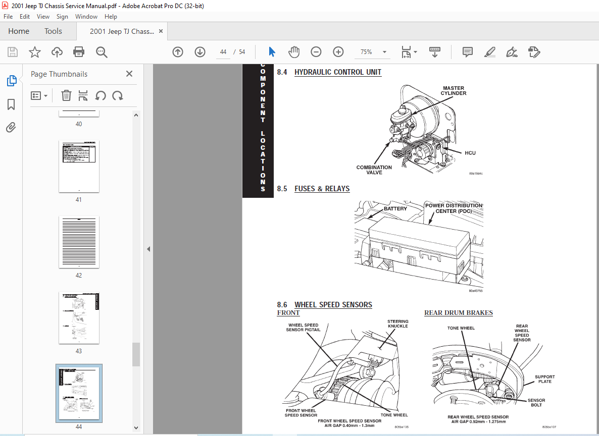
8 4 HYDRAULIC CONTROL UNIT 42
8 5 FUSES & RELAYS 42
8 6 WHEEL SPEED SENSORS 42
8 7 WHEEL SPEED SENSOR CONNECTORS 43
8 8 BRAKE SWITCHES 43
8 8 1 PARKING BRAKE 43
8 8 2 BRAKE SWITCH 43
9 0 CONNECTOR PINOUTS 45
BRAKE LAMP SWITCH – GRAY 6 WAY 45
BRAKE WARNING INDICATOR SWITCH – BLACK 2 WAY 45
CONTROLLER ANTILOCK BRAKE – 25 WAY 45
LEFT FRONT WHEEL SPEED SENSOR – 2 WAY 46
LEFT FRONT WHEEL SPEED SENSOR CONNECTOR
(SENSOR SIDE) – 2 WAY 46
LEFT REAR WHEEL SPEED SENSOR – 2 WAY 46
LEFT REAR WHEEL SPEED SENSOR CONNECTOR
(SENSOR SIDE) – 2 WAY 46
FUSES (PDC) 48
ANTILOCK BRAKE RELAY – 5 WAY 48
PUMP MOTOR CONNECTOR – 2 WAY 49
RIGHT FRONT WHEEL SPEED SENSOR – BLACK 2 WAY 49
RIGHT FRONT WHEEL SPEED SENSOR CONNECTOR
(SENSOR SIDE) – 2 WAY 49
RIGHT REAR WHEEL SPEED SENSOR – BLACK 2 WAY 49
RIGHT REAR WHEEL SPEED SENSOR CONNECTOR
(SENSOR SIDE) – 2 WAY 50
10 0 SCHEMATIC DIAGRAMS 51
TJ BODY TEVES MARK IVG 51
VIDEO PREVIEW OF THE MANUAL:
IMAGES PREVIEW OF THE MANUAL:

PLEASE NOTE:
- This is the SAME MANUAL used by the dealerships to diagnose your vehicle
- No waiting for couriers / posts as this is a PDF manual and you can download it within 2 minutes time once you make the payment.
- Your payment is all safe and the delivery of the manual is INSTANT – You will be taken to the DOWNLOAD PAGE.
- So have no hesitations whatsoever and write to us about any queries you may have : heydownloadss @gmail.com
S.V