1994 NISSAN 300ZX Z32 Series Service Manual PDF DOWNLOAD
FILE DETAILS:
1994 NISSAN 300ZX Z32 Series Service Manual PDF DOWNLOAD
Language : English
Pages : 1162
Downloadable :Yes
File Type : PDF
IMAGES PREVIEW OF THE MANUAL:
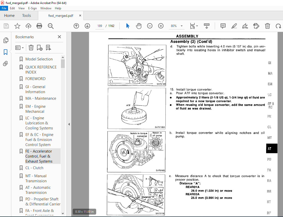
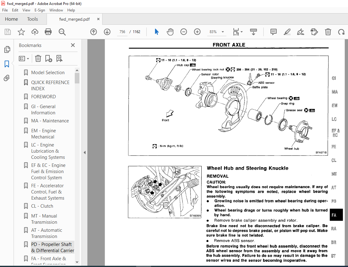

TABLE OF CONTENTS:
1994 NISSAN 300ZX Z32 Series Service Manual PDF DOWNLOAD
Model Selection 0
QUICK REFERENCE INDEX 1
FOREWORD 2
GI – General Information 0
MA – Maintenance 0
EM – Engine Mechanical 0
LC – Engine Lubrication & Cooling Systems 0
EF & EC – Engine Fuel & Emission Control System 0
FE – Accelerator Control, Fuel & Exhaust Systems 0
CL – Clutch 0
MT – Manual Transmission 0
AT – Automatic Transmission 0
PD – Propeller Shaft & Differential Carrier 0
FA – Front Axle & Front Suspension 0
RA – Rear Axle & Rear Suspension 0
BR – Brake System 0
ST – Steering System 0
BF – Body 0
HA – Heater & Air Conditioner 0
EL – Electrical System 0
IDX – Alphabetical Index 1
Foldout 0
Inch to Metric Conversion Table 3
Quick Reference Chart 4
QUICK REFERENCE INDEX 0
TABLE OF CONTENTS 5
PREPARATION AND PRECAUTIONS 6
Special Service Tools 6
Service Notice 7
Supplemental Restraint System “AIR BAG” 8
DESCRIPTION 9
Cross-Sectional View 9
Hydraulic Control Circuits 10
Shift Mechanism 11
Control System 13
TROUBLE DIAGNOSES 15
Contents 15
TROUBLE DIAGNOSES – A/T Shift Lock System 92
Contents 92
ON-VEHICLE SERVICE 101
Control Valve Assembly and Accumulators Inspection 101
Revolution Sensor Replacement 102
Rear Oil Seal Replacement 102
Parking Components Inspection 102
Inhibitor Switch Adjustment 103
Kickdown Switch Adjustment 103
REMOVAL AND INSTALLATION 104
Removal 104
Installation 104
MAJOR OVERHAUL 106
RE4R01A 106
RE4R03A 108
Oil Channel – RE4R01A 110
Oil Channel – RE4R03A 111
Locations of Needle Bearings, Thrust Washers and Snap Rings – RE4R01A 112
Locations of Needle Bearings, Thrust Washers and Snap Rings – RE4R03A 113
DISASSEMBLY 114
Disassembly 114
REPAIR FOR COMPONENT PARTS 125
Oil Pump 125
Control Valve Assembly 129
Control Valve Upper Body 135
Control Valve Lower Body 140
Reverse Clutch 142
High Clutch 146
Forward and Overrun Clutches 148
Low & Reverse Brake 152
Forward Clutch Drum Assembly – RE4R01A 156
Forward Clutch Drum Assembly – RE4R03A 159
Rear Internal Gear and Forward Clutch Hub 162
Band Servo Piston Assembly 165
Parking Pawl Components 169
ASSEMBLY 171
Assembly (1) 171
Adjustment 176
Assembly (2) 180
SERVICE DATA AND SPECIFICATIONS (SDS) 190
General Specifications 190
Specifications and Adjustment – RE4R01A 190
Specifications and Adjustment – RE4R03A 194
QUICK REFERENCE INDEX 0
TABLE OF CONTENTS 198
GENERAL SERVICING 199
Precautions 199
Supplemental Restraint System “AIR BAG” 199
Circuit Breaker Inspection 199
Clip and Fastener 200
BODY END 202
Body Front End 202
Body Rear End and Opener 204
DOOR 207
Power Window 208
Power Door Lock 210
MULTI-REMOTE CONTROL SYSTEM 213
Wiring Diagram 213
Circuit Diagram for Quick Pinpoint Check 215
Trouble Diagnoses Preliminary Inspection 216
Trouble Diagnoses 217
Replacing Remote Controller or Control Unit 223
INSTRUMENT PANEL 224
INTERIOR AND EXTERIOR 226
Interior 226
Exterior 233
T-BAR ROOF 242
CONVERTIBLE ROOF 244
Wiring Diagram 244
Storage Lid 246
Top Cover and Headliner 247
Linkage 248
Adjustment 250
SEAT 251
WINDSHIELD AND WINDOWS 254
Windshield 254
Side Window 255
Back Door Window 256
REAR AIR SPOILER AND MIRROR 257
Rear Air Spoiler 257
Door Mirror 257
BODY ALIGNMENT 259
Engine Compartment 259
Underbody 261
SUPPLEMENTAL RESTRAINT SYSTEM (SRS) 266
Precautions for SRS “Air Bag” Service 266
Special Service Tools 266
Commercial Service Tools 266
Description 267
SRS Component Parts Location and Caution Labels 268
Maintenance Items 271
Removal and Installation – Diagnosis (Control) Unit and Sensors 272
Removal – Air Bag Module and Spiral Cable 273
Removal – Front Passenger Air Bag Module 274
Installation – Air Bag Module and Spiral Cable 275
Installation – Front Passenger Air Bag Module 277
Scrapping Air Bag 277
TROUBLE DIAGNOSES – Supplemental Restraint System (SRS) 280
Contents 280
QUICK REFERENCE INDEX 0
TABLE OF CONTENTS 291
PRECAUTIONS AND PREPARATION 292
Precautions 292
Special Service Tools 292
Commercial Service Tools 292
CHECK AND ADJUSTMENT 293
Checking Brake Fluid Level 293
Checking Brake System 293
Changing Brake Fluid 293
Bleeding Brake System 293
BRAKE HYDRAULIC LINE 294
Removal and Installation 294
Inspection 294
BRAKE PEDAL AND BRACKET 295
Removal and Installation 295
Inspection 295
Adjustment 295
MASTER CYLINDER 297
Removal 297
Disassembly 297
Inspection 298
Assembly 298
Installation 298
BRAKE BOOSTER 299
Removal and Installation 299
Inspection 299
VACUUM PIPING 300
Removal and Installation 300
Inspection 300
FRONT DISC BRAKE (OPF25VA) 301
Pad Replacement 301
Removal and Installation 301
Disassembly 302
Inspection 302
Assembly 303
Inspection (On-vehicle) 303
REAR DISC BRAKE (OPZ11V) 304
Pad Replacement 304
Removal and Installation 305
Disassembly 305
Inspection 305
Assembly 306
Inspection (On-vehicle) 306
PARKING BRAKE CONTROL 307
Removal and Installation 307
Inspection 307
Adjustment 307
PARKING DRUM BRAKE (DS17HD) 308
Shoe Replacement 308
Shoe Clearance Adjustment 309
Breaking in Parking Brake Shoes 309
Drum Inspection 309
ANTI-LOCK BRAKE SYSTEM 310
System Components 310
Hydraulic Circuit 310
Wiring Diagram 311
Removal and Installation 312
TROUBLE DIAGNOSES 313
Contents 313
SERVICE DATA AND SPECIFICATIONS (SDS) 336
General Specifications 336
Inspection and Adjustment 336
QUICK REFERENCE INDEX 0
TABLE OF CONTENTS 337
PRECAUTIONS AND PREPARATION 338
Precautions 338
Special Service Tools 338
Commercial Service Tools 339
CLUTCH SYSTEM 340
INSPECTION AND ADJUSTMENT 342
Adjusting Clutch Pedal 342
Bleeding Procedure 343
HYDRAULIC CLUTCH CONTROL 344
Clutch Master Cylinder 344
Operating Cylinder 345
Clutch Booster 345
CLUTCH RELEASE MECHANISM 348
CLUTCH DISC AND CLUTCH COVER 350
Clutch Disc 350
Clutch Cover and Flywheel 351
SERVICE DATA AND SPECIFICATIONS (SDS) 351
General Specifications 351
Inspection and Adjustment 351
QUICK REFERENCE INDEX 0
TABLE OF CONTENTS 352
PREPARATION 354
Special Service Tools 354
PRECAUTIONS 355
ENGINE AND EMISSION CONTROL OVERALL SYSTEM 356
ECCS Component Parts Location 356
System Diagram 358
System Chart 360
Vacuum Hose Drawing 361
Circuit Diagram 363
ENGINE AND EMISSION CONTROL PARTS DESCRIPTION 364
Engine Control Module (ECM)-ECCS Control Module 364
Camshaft Position Sensor (CMPS) 364
Mass Air Flow Sensor (MAFS) 364
Engine Coolant Temperature Sensor (ECTS) 365
Throttle Position Sensor (TPS) & Soft/Hard Closed Throttle Position (CTP) Switch 365
Fuel Injector 366
Pressure Regulator 366
Heated Oxygen Sensor (HO2S) 366
Fuel Pump 366
Fuel Damper 367
Power Transistor Unit & Ignition Coil 367
Idle Air Control Valve (IACV)-Air Regulator 367
Idle Air Adjusting (IAA) Unit 367
Idle Air Control Valve (IACV)-Auxiliary Air Control (AC) Valve 368
Power Steering Oil Pressure Switch 368
Vehicle Speed Sensor (VSS) 368
Knock Sensor (KS) 368
Exhaust Gas Recirculation (EGR) Valve 368
EGR Control (EGRC)-Solenoid Valve 369
Pressure Regulator Vacuum Relief (PRVR) Control Solenoid Valve 369
Wastegate Valve Control Solenoid Valve 369
Fuel Filter 369
Data Link Connector for CONSULT 369
EGR Temperature Sensor 370
Valve Timing Control Solenoid Valve 370
Carbon Canister 370
Fuel Temperature Sensor 370
ENGINE AND EMISSION CONTROL SYSTEM DESCRIPTION 371
Multiport Fuel Injection (MFI) System 371
Electronic Ignition (EI) System 373
Idle Air Control (IAC) System 374
Fuel Pump Control 375
Exhaust Gas Recirculation (EGR) System 376
Fuel Pressure Regulator Control 377
Acceleration Cut Control 377
Valve Timing Control 378
Cooling Fan Control 380
Wastegate Valve Control 381
Fail-safe System 382
Direct Ignition System 384
IDLE SPEED/IGNITION TIMING/IDLE MIXTURE RATIO INSPECTION 386
TROUBLE DIAGNOSES 391
Contents 391
MULTIPORT FUEL INJECTION SYSTEM INSPECTION 539
Releasing Fuel Pressure 539
Fuel Pressure Check 539
Injector Removal and Installation 540
EVAPORATIVE EMISSION SYSTEM 541
Description 541
Inspection 541
CRANKCASE EMISSION CONTROL SYSTEM 543
Description 543
Inspection 543
SERVICE DATA AND SPECIFICATIONS (SDS) 544
General Specifications 544
Inspection and Adjustment 544
QUICK REFERENCE INDEX 0
TABLE OF CONTENTS 545
PRECAUTIONS AND PREPARATION 547
Precautions 547
Special Service Tools 547
HARNESS CONNECTOR 548
Description 548
STANDARDIZED RELAY 549
Description 549
POWER SUPPLY ROUTING 552
Wiring Diagram 552
Fuse Block Internal Circuit 554
Fuse 555
Fusible Link 555
BATTERY 556
How to Handle Battery 556
Service Data and Specifications (SDS) 558
STARTING SYSTEM 559
Wiring Diagram 559
Construction 560
Removal and Installation 560
Service Data and Specifications (SDS) 561
CHARGING SYSTEM 562
Wiring Diagram 562
Construction 563
Removal and Installation 564
Service Data and Specifications (SDS) 565
COMBINATION SWITCH 566
Combination Switch/Check 566
Combination Switch/Replacement 567
INSTRUMENT SWITCH 568
Check 568
HEADLAMP 570
Operation (Daytime light system equipped model) 570
Schematic 570
Wiring Diagram 572
Aiming Adjustment 574
Bulb Replacement 575
EXTERIOR LAMP 576
Clearance, License, Tail and Stop Lamps/Wiring Diagram 576
Back-up Lamp/Wiring Diagram 577
Front Fog Lamp/Wiring Diagram 578
Turn Signal and Hazard Warning Lamps/Wiring Diagram 579
Stop and Tail Lamp Sensor Check 580
Tail Lamp 580
Combination Flasher Unit Check 580
Bulb Specifications 580
INTERIOR LAMP 581
Illumination/Wiring Diagram 581
Interior, Spot, Foot and Luggage Room Lamps/Wiring Diagram 582
METER AND GAUGES 584
Combination Meter 584
Speedometer, Tachometer, Temp , Oil, Fuel and Boost Gauges/Wiring Diagram 585
Inspection/Fuel Gauge and Water Temperature Gauge 586
Fuel Tank Gauge Unit Check 587
Fuel Warning Lamp Sensor Check 587
Thermal Transmitter Check 588
Oil Pressure Sending Unit Check 588
Boost Sensor Check 588
Vehicle Speed Sensor Signal Check 588
WARNING LAMPS AND CHIME 589
Warning Lamps/Schematic 589
Warning Lamps/Wiring Diagram 590
Warning Chime/Wiring Diagram 591
Diode Check 592
Warning Chime Check 592
TIME CONTROL SYSTEM 593
Description 593
Wiring Diagram 594
Trouble Diagnoses 595
WIPER AND WASHER 607
Front Wiper and Washer/Wiring Diagram 607
Rear Wiper and Washer/Wiring Diagram 608
Headlamp Washer/Wiring Diagram 609
Installation 610
Washer Nozzle Adjustment 611
Check Valve 611
Wiper Amplifier Check 611
HORN, CIGARETTE LIGHTER, CLOCK 612
Wiring Diagram 612
REAR WINDOW DEFOGGER & HEATER MIRROR 613
Wiring Diagram 613
Filament Check 614
Filament Repair 615
AUDIO AND POWER ANTENNA 616
Audio/Wiring Diagram 616
Power Antenna/Wiring Diagram 618
Location of Antenna 619
Antenna Rod Replacement 619
Radio Fuse Check 620
Window Antenna Repair 621
AUTOMATIC SPEED CONTROL DEVICE (ASCD) 622
Component Parts and Harness Connector Location 622
Wiring Diagram 623
Trouble Diagnoses 624
THEFT WARNING SYSTEM 643
Component Parts and Harness Connector Location 643
Wiring Diagram 644
Trouble Diagnoses 648
LOCATION OF ELECTRICAL UNITS 666
Engine Compartment 666
Passenger Compartment 667
Luggage Compartment 668
HARNESS LAYOUT 670
Outline 670
Engine Room Harness 671
Engine Control Harness 674
Main Harness 676
Air Bag Harness 679
Body Harness 680
Door Harness LH 686
Door Harness RH 686
Back Door Harness 687
Alternator Harness 687
QUICK REFERENCE INDEX 0
TABLE OF CONTENTS 688
PRECAUTIONS 689
Supplemental Restraint System “AIR BAG” 689
Parts Requiring Angular Tigihtening 689
Liquid Gasket Application Procedure 689
PREPARATION 690
Special Service Tools 690
Commercial Service Tools 692
OUTER COMPONENT PARTS 693
COMPRESSION PRESSURE 696
Measurement of Compression Pressure 696
OIL PAN 697
Removal 697
Installation 698
TIMING BELT 699
Removal 699
Inspection 701
Installation 702
OIL SEAL REPLACEMENT 706
THROTTLE BODIES 708
Precaution 708
Installation 708
CYLINDER HEAD 710
Removal 711
Disassembly 712
Inspection 713
Assembly 718
Installation 719
TURBOCHARGERS 721
Removal 721
Inspection 723
CHARGE AIR COOLERS 726
Removal 726
ENGINE REMOVAL 727
M/T model 728
A/T model 729
CYLINDER BLOCK 730
Disassembly 731
Inspection 731
Assembly 737
SERVICE DATA AND SPECIFICATIONS (SDS) 740
General Specifications 740
Inspection and Adjustment 741
QUICK REFERENCE INDEX 0
TABLE OF CONTENTS 748
PRECAUTIONS AND PREPARATION 749
Precautions 749
Special Service Tools 749
Commercial Service Tools 749
FRONT AXLE AND FRONT SUSPENSION 751
ON-VEHICLE SERVICE 752
Front Axle and Front Suspension Parts 752
Front Wheel Bearing 754
Front Wheel Alignment 754
FRONT AXLE 756
Wheel Hub and Steering Knuckle 756
FRONT SUSPENSION 760
Coil Spring and Shock Absorber 761
Third Link and Upper Link 762
Transverse Link and Lower Ball Joint 764
Tension Rod and Stabilizer Bar 765
ADJUSTABLE SHOCK ABSORBER 766
Trouble Diagnoses 767
SERVICE DATA AND SPECIFICATIONS (SDS) 773
General Specifications 773
Inspection and Adjustment 773
QUICK REFERENCE INDEX 0
TABLE OF CONTENTS 775
ACCELERATOR CONTROL SYSTEM 776
Adjusting Accelerator Wire 776
FUEL SYSTEM 777
EXHAUST SYSTEM 779
QUICK REFERENCE INDEX 0
ELECTRICAL SYSTEM 0
1994 NISSAN 300ZX ECCS WIRING DIAGRAM 781
1994 NISSAN 300ZX CIRCUIT DIAGRAM 785
QUICK REFERENCE INDEX 0
TABLE OF CONTENTS 790
PRECAUTIONS 791
Precautions for Supplemental Restraint System “AIR BAG” 791
General Precautions 791
Precautions for Multiport Fuel Injection System or ECCS Engine 793
Precautions for Three Way Catalyst 793
Precautions for Turbocharger 793
Engine Oils 794
Precautions for Fuel 795
HOW TO USE THIS MANUAL 796
HOW TO READ WIRING DIAGRAMS 798
HOW TO FOLLOW FLOW CHART IN TROUBLE DIAGNOSES 801
CONSULT CHECKING SYSTEM 804
Function and System Application 804
Checking Equipment 804
IDENTIFICATION INFORMATION 805
Model Variation 805
Identification Number 807
Dimensions 809
Wheels and Tires 809
LIFTING POINTS AND TOW TRUCK TOWING 810
Garage Jack and Safety Stand 810
2-pole Lift 811
Tow Truck Towing 811
TIGHTENING TORQUE OF STANDARD BOLTS 813
SAE J1930 TERMINOLOGY LIST 814
QUICK REFERENCE INDEX 0
TABLE OF CONTENTS 818
PRECAUTIONS 820
Supplemental Restraint System “AIR BAG” 820
Introduction 820
Identification 820
Precautions for Working with HFC-134a )R-134a) 822
General Refrigerant Precautions 822
Precautions for Refrigerant Connection 823
Precautions for Servicing Compressor 824
DESCRIPTION – Overall System 825
Features – Auto Air Conditioner 825
Acceleration Cut System 826
Water Cock Control System 826
Control Operation – Manual Air Conditioner 826
Control Operation – Auto Air Conditioner 827
Component Layout 828
Air Flow 829
DESCRIPTION – Refrigerant System 831
Refrigeration Cycle 831
PREPARATION 832
Special Service Tools 832
HFC-134a (R-134a) Service Tools and Equipment 833
Precautions for Service Equipment 835
SERVICE PROCEDURES 837
HFC-134a (R-134a) Service Procedure 837
Refrigerant Lines 839
Compressor Mounting 841
Belt Tension 841
Fast Idle Control Device (FICD) 841
Removal and Installation – Compressor 842
LUBRICATION OIL – Checking and Adjusting 843
Lubrication Oil 843
Maintenance of Oil Quantity in Compressor 843
Checking and Adjusting 843
COMPRESSOR – Model DK-16H (ZEXEL make) 845
Compressor Clutch 845
DIAGNOSES – Overall System 847
How to Perform Trouble Diagnoses for Quick and Accurate Repair – Manual Air Conditioner 847
How to Perform Trouble Diagnoses for Quick and Accurate Repair – Auto Air Conditioner 848
Operational Check – Manual Air Conditioner 849
Operational Check – Auto Air Conditioner 850
Performance Chart 853
Performance Test Diagnoses 855
TROUBLE DIAGNOSES – Manual Air Conditioner 860
Contents 860
TROUBLE DIAGNOSES – Auto Air Conditioner 890
Contents 890
SYSTEM DESCRIPTION – Manaul Air Conditioner 940
Control Switches 940
Specifications 940
SYSTEM DESCRIPTION – Auto Air Conditioner 942
Specifications 942
System Operation 945
SERVICE DATA AND SPECIFICATIONS (SDS) 949
General Specifications 949
Inspection and Adjustment 949
QUICK REFERENCE INDEX 0
QUICK REFERENCE INDEX 0
TABLE OF CONTENTS 957
PRECAUTIONS/PREPARATION 958
Supplemental Restraint System “AIR BAG” 958
Liquid Gasket Application Procedure 958
Special Service Tools 959
ENGINE LUBRICATION SYSTEM 960
Lubrication Circuit 960
Oil Pressure Check 961
Oil Filter Bracket (Turbocharger model) 961
Oil Pump 961
Oil Cooler (Turbocharger model) 963
ENGINE COOLING SYSTEM 964
Cooling Circuit 964
System Check 964
Water Pump 965
Thermostat 966
Cooling Fan (Crankshaft driven) 967
Radiator 968
Cooling Fan (Motor driven) 968
SERVICE DATA AND SPECIFICATIONS (SDS) 969
Engine Lubrication System 969
Engine Cooling System 969
QUICK REFERENCE INDEX 0
TABLE OF CONTENTS 970
PRECAUTIONS 971
Supplemental Restraint System “AIR BAG” 971
GENERAL MAINTENANCE 972
PERIODIC MAINTENANCE 974
Schedule 1 975
Schedule 2 976
RECOMMENDED FLUIDS AND LUBRICANTS 977
Fluids and Lubricants 977
SAE Viscosity Number 977
ENGINE MAINTENANCE 978
Checking Drive Belts 978
Changing Engine Coolant 979
Checking Fuel Lines 980
Changing Fuel Filter 981
Changing Air Cleaner Filter 981
Changing Engine Oil 981
Changing Oil Filter 982
Changing Spark Plugs 982
Checking Vapor Lines 983
CHASSIS AND BODY MAINTENANCE 984
Checking Exhaust System 984
Checking Clutch Fluid Level and Leaks 984
Checking M/T Oil 984
Changing M/T Oil 984
Checking A/T Fluid 984
Changing A/T Fluid 985
Checking Differentail Gear Oil 985
Changing Differential Gear Oil 985
Balancing Wheels 985
Tire Rotation (Non-Turbocharger model only) 986
Checking Brake Fluid Level and Leaks 986
Checking Brake Lines and Cables 986
Checking Disc Brake 986
Checking Steering Gear and Linkage 987
Checking Power Steering Fluid and Lines 987
Checking SUPER HICAS Linkage (With SUPER HICAS system) 987
Lubricating Locks, Hinges and Hood Latches 988
Checking Seat Belts, Buckles, Retractors, Anchors and Adjusters 988
SERVICE DATA AND SPECIFICATIONS 989
Engine Maintenance 989
Chassis and Body Maintenance 989
QUICK REFERENCE INDEX 0
TABLE OF CONTENTS 990
PREPARATION 991
Special Service Tools 991
Commercial Service Tool 993
ON-VEHICLE SERVICE 994
Replacing Rear Oil Seal 994
Position Switch Check 994
REMOVAL AND INSTALLATION 995
Removal 995
Installation 995
MAJOR OVERHAUL 996
Case Components 996
Gear Components 997
Shift Control Components 999
DISASSEMBLY 1001
Case Components 1001
Shift Control Components 1002
Gear Components 1003
INSPECTION 1007
Shift Control Components 1007
Gear Components 1007
ASSEMBLY 1009
Gear Components 1009
Shift Control Components 1017
Case Components 1018
SERVICE DATA AND SPECIFICATIONS (SDS) 1020
General Specification 1020
Inspection and Adjustment 1020
QUICK REFERENCE INDEX 0
TABLE OF CONTENTS 1022
PREPARATION 1023
Special Service Tools 1023
Commercial Service Tool 1026
PROPELLER SHAFT 1027
On-vehicle Service 1028
Removal 1028
Installation 1029
Inspection 1029
Disassembly 1030
Assembly 1030
ON-VEHICLE SERVICE/REMOVAL AND INSTALLATION 1031
Front Oil Seal Replacement (R200V) 1031
Side Oil Seal Replacement 1031
Removal 1032
Installation 1032
FINAL DRIVE 1033
Model R200V 1033
Model R230V 1034
DISASSEMBLY 1035
Pre-inspection 1035
Differential Carrier 1035
Differential Case 1037
INSPECTION 1038
Ring Gear and Drive Pinion 1038
Bearing 1038
Differential Case Asembly 1038
ADJUSTMENT (R200V) 1039
Side Bearing Preload 1039
Pinion Gear Height and Pinion Bearing Preload 1040
ADJUSTMENT (R230V) 1045
Side Bearing Preload 1045
Pinion Gear Height 1046
ADJUSTMENT 1049
Tooth Contact 1049
ASSEMBLY 1050
Differential Case 1051
Differential Carrier 1051
SERVICE DATA AND SPECIFICATIONS (SDS) 1056
Propeller Shaft 1056
Final Drive 1056
QUICK REFERENCE INDEX 0
TABLE OF CONTENTS 1059
PRECAUTIONS AND PREPARATION 1060
Precautions 1060
Special Service Tools 1060
Commercial Service Tools 1061
REAR AXLE AND REAR SUSPENSION 1062
ON-VEHICLE SERVICE 1063
Rear Axle and Rear Suspension Parts 1063
Rear Wheel Bearing 1063
Rear Wheel Alignment 1063
Drive Shaft 1065
REAR AXLE AND REAR SUSPENSION ASSEMBLY 1066
Removal and Installation 1066
REAR AXLE 1067
Wheel Hub and Axle Housing 1067
Drive Shaft 1070
REAR SUSPENSION 1074
Coil Spring and Shock Absorber 1075
Multi-link and Lower Ball Joint 1075
Stabilizer Bar 1076
ADJUSTABLE SHOCK ABSORBER 1077
Removal and Installation 1077
Inspection 1077
Trouble Diagnosis 1077
SUPER HICAS 1078
Rear Wheel Alignment 1078
Rear Axle Housing Ball Joint 1078
SERVICE DATA AND SPECIFICATIONS (SDS) 1080
General Specifications 1080
Inspection and Adjustment 1081
QUICK REFERENCE INDEX 0
TABLE OF CONTENTS 1082
PRECAUTIONS AND PREPARATION 1083
Supplemental Restraint System “AIR BAG” 1083
Steering System 1083
Special Service Tools 1083
Commercial Service Tools 1085
CONSULT Program Card 1085
ON-VEHICLE SERVICE 1086
Checking Steering Wheel Play 1086
Checking Neutral Position on Steering Wheel 1086
Front Wheel Turning Angle 1086
Checking Gear Housing Movement 1087
Adjusting Rack Retainer 1087
Checking and Adjusting Drive Belts (For power steering) 1087
Checking Fluid Level 1087
Checking Fluid Leakage 1088
Bleeding Hydraulic System 1088
Checking Steering Wheel Turning Force (For power steering) 1088
Checking Hydraulic System 1089
STEERING WHEEL AND STEERING COLUMN 1090
Removal 1090
Installation 1091
Disassembly and Assembly 1091
Inspection 1092
POWER STEERING GEAR AND LINKAGE (Model PR26SE) 1093
Removal and Installation 1093
Disassembly 1096
Inspection 1096
Assembly 1097
Adjustment 1102
POWER STEERING OIL PUMP 1104
Pre-disassembly Inspection 1104
Disassembly 1104
Inspection 1105
Assembly 1105
TWIN ORIFICE POWER STEERING SYSTEM 1107
Hydraulic Circuit 1107
Schematic 1107
Wiring Diagram 1108
Trouble Diagnoses 1109
SUPER HICAS SYSTEM 1118
HICAS Component Parts Location 1118
System Diagram 1118
On-vehicle Service 1119
Repair of Component Parts 1121
Trouble Diagnoses 1126
SERVICE DATA AND SPECIFICATIONS (SDS) 1161
General Specifications 1161
Inspection and Adjustment 1161
VIDEO PREVIEW:
DESCRIPTION:
1994 NISSAN 300ZX Z32 Series Service Manual PDF DOWNLOAD
FOREWORD
- This manual contains maintenance and repair procedures for the 1994 Nissan 300ZX. In order to assure your safety and the efficient functioning of the vehicle, this manual should be read thoroughly.
- It is especially important that the PRECAUTIONS in the GI section be completely understood before starting any repair task.
- All information in this manual is based on the latest product information at the time of publication. The right is reserved to make changes in specifications and methods at any time without notice.
IMPORTANT SAFETY NOTICE
- The proper performance of service Is essential for both the safety of the technician and the efficient functioning of the vehicle.
- The service methods In this Service Manual are described in such a manner that the service may be performed safely and accurately.
- Service varies with the procedures used, the skills of the technician and the tools and parts available.
- Accordingly, anyone using service procedures, tools or parts which are not specifically recommended by NISSAN must first completely satisfy himself that neither his safety nor the vehicle’s safety will be Jeopardized by the service method selected .
PLEASE NOTE:
- This is the same manual used by the dealers to diagnose and troubleshoot your vehicle
- You will be directed to the download page as soon as the purchase is completed. The whole payment and downloading process will take anywhere between 2-5 minutes
- Need any other service / repair / parts manual, please feel free to contact [email protected] . We still have 50,000 manuals unlisted
G.P