

")
1985 Chevrolet GMC Light Duty Truck Wiring Manual – PDF DOWNLOAD
DESCRIPTION:
1985 ST 352 85 Chevrolet GMC Light Duty Truck Wiring Manual – PDF DOWNLOAD
WIRING DIAGRAMS DESCRIPTION:
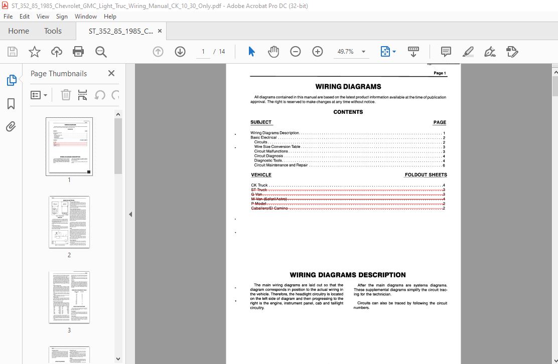
The main wiring diagrams are laid out so that the After the main diagrams are systems diagrams. diagram corresponds in position to the actual wiring in These supplemental diagrams simplify the circuit vehicle. Therefore, the headlight circuitry is located for the technician. on the left side of diagram and then progressing to the right is the engine, instrument panel, cab and taillight Circuits can also be traced by following the circuit circuitry. numbers
BASIC ELECTRICAL:
PARALLEL CIRCUITS (Figure 1)
In parallel circuits, the electrical devices are connected by parallel wires that are joined at the start of the circuit. the current divides: part of it flows into one device, part into another. With circuits in parallel, each circuit can be switched on and off by itself since each circuit receives electricity directly from the power supply.
CIRCUIT COMPONENTS (Figure 2)
The usual circuit path starts at the power supply which is the battery/generator system. Next in the circuit is the circuit protection component which can be a fusible link, a fuse, or a circuit breaker. Then the circuit goes to the circuit controller which can be a switch or a relay. From ‘the circuit controller the circuit goes to the circuit load. The circuit load can be one light or many lights in parallel, an electric motor or a solenoid. After the electricity has passed through the load it must return to the power supply via the ground path. The ground path can be a wire in the harness or it could be through the load housing into the body orframe, thus returning the electricity to the power supply. The body and frame are connected by flexible ground straps.
FUSIBLE LINK
A fusible link is a section of wire that is usually four gage sizes smaller than the circuit it protects. A special insulation is used that swells when heated by the wire. Fusible links are usually found in the engine compartment harnesses. The function of the fusible link is to melt open when an overload occurs, thus preventing any damage to the circuit.
FUSES
The most common protector in the vehicle circuit is a fuse. A fuse consists of a fine wire or strip of metal, inside a glass tube or plastic housing. The strip melts and interrupts the flow of current in the circuit when there is an overload caused by an unwanted short or ground. The fuse is designed to melt before the wiring or electrical components in a circuit can be damaged. Naturally, the cause must be located and corrected before the fuse is replaced or the new fuse will also blow. Since different circuits handle different amounts of , current, fuses of various ratings are used. Fuses are rated in amperes. Be sure to replace a blown fuse with a fuse of the connecting rating.
CIRCUIT BREAKERS
Circuit breakers are another form of circuit protector. There are two types of circuit breakers; automatic reset and remote reset The automatic reset breaker opens when excess current heats a bimetallic strip, causing the strip to bend and open a set of contacts. Then the strip cools and closes the contacts. So the circuit breaker opens and closes until the excess current condition is corrected or the circuit is disconnected from the power supply. The remote reset circuit breaker has a heating wire wound around the bimetallic strip. When an excess current happens, the strip heats, bends, and opens the contacts. Then a small current flows through the heating wire, keeping the strip hot and the contacts open. This type of breaker will stay open until either the power supply is disconnected from the circuit or the breaker is removed from the circuit. Then the breaker can cool and reset
TABLE OF CONTENTS:
1985 Chevrolet GMC Light Duty Truck Wiring Manual – PDF DOWNLOAD
Wiring Diagrams Description …………………………………………………………… 1
Basic Electrical ……………………………………………………………………. 2
Circuits ………………………………………………………………………… 2
Wire Size Conversion Table ………………………………………………………….. 3
Circuit Malfunctions ……………………………………………………………….. 3
Circuit Diagnosis …………………………………………………………………. 4
Diagnostic Tools ………………………………………………………………….. 4
Circuit Maintenance and Repair ………………………………………………………. 6
VIDEO PREVIEW OF THE MANUAL:
IMAGES PREVIEW OF THE MANUAL:


PLEASE NOTE:
- This is the SAME MANUAL used by the dealerships to diagnose your vehicle
- No waiting for couriers / posts as this is a PDF manual and you can download it within 2 minutes time once you make the payment.
- Your payment is all safe and the delivery of the manual is INSTANT – You will be taken to the DOWNLOAD PAGE.
- So have no hesitations whatsoever and write to us about any queries you may have : heydownloadss @gmail.com


