

1969-1975 Cessna 150 Series Parts Catalog Manual – PDF DOWNLOAD
IMAGES PREVIEW OF THE MANUAL:

DESCRIPTION:
1969-1975 Cessna 150 Series Parts Catalog Manual – PDF DOWNLOAD
INTRODUCTION.
This illustrated parts catalog has been prepared to aid
you in easily and quickly identifying parts of the models
covered herein.
This catalog features an index system consisting of:
l. An alphabetical index located in the front of the
catalog.
2. A numerical index located in the back of the
catalog, which lists all parts and figures in
which they appear.
STANDARD PARTS.
Many parts having standard usage have been incorporated
into the Cessna Standard System. Parts in this
group are designated with the part number prefix “S”.
For standard hardware ítems such as Tinnerman nuts,
clamps, etc., “AN” and “NAS” numbers have been
used.
USABLE ON CODES …• Serial listings in this catalog
are noted by a letter code located in the usable on code
column which is the extreme right hand column of the
parts list page. Usable on codes are applicable only
to the figure on which they appear. The code letters
and the serials to which they apply are Usted at the
end of the figure.
If no usable on code appears opposite a first column
listing of the figure, the usage is applicable to all
models and serials covered by this catalog. If no
usable on code appears opposite any indented listing,
the usage is appUcable to all models and serials covered
by the figure on which it appears.
TABLE OF CONTENTS:
1969-1975 Cessna 150 Series Parts Catalog Manual – PDF DOWNLOAD
Cover ……………………………………………………….. 1
Introduction………………………………………………….. 5
Upholstery & Interior Trim……………………………………… 19
Alphabetical Index…………………………………………….. 33
A – B…………………………………………………….. 34
B (cont) – C………………………………………………. 35
C (cont) – D………………………………………………. 36
D (cont) – E………………………………………………. 37
E (cont) – F………………………………………………. 38
F (cont) – G………………………………………………. 39
G (cont) – I………………………………………………. 40
I (cont) – L………………………………………………. 41
L (cont) – N………………………………………………. 42
O – P…………………………………………………….. 43
P (cont) – R………………………………………………. 44
S………………………………………………………… 45
S (cont) – T………………………………………………. 46
T (cont) – V………………………………………………. 47
V (cont) – Z………………………………………………. 48
Parts Listing / Figures………………………………………… 49
Fig 1. Miscellaneous Bulk Items……………………………… 52
Fig 2. (Sheet 1 of 5) Placards, Nameplates & Exterior Markings….. 56
Fig 2. (Sheet 2 of 5) Placards, Nameplates & Exterior Markings….. 57
Fig 2. (Sheet 3 of 5) Placards, Nameplates & Exterior Markings….. 58
Fig 2. (Sheet 4 of 5) Placards, Nameplates & Exterior Markings….. 59
Fig 2. (Sheet 5 of 5) Placards, Nameplates & Exterior Markings….. 60
Fig 2A. (Sheet 1 of 3) Placards, Nameplates & Exterior Markings…. 64
Fig 2A. (Sheet 2 of 3) Placards, Nameplates & Exterior Markings…. 65
Fig 2A. (Sheet 3 of 3) Placards, Nameplates & Exterior Markings…. 66
Fig 2B. (Sheet 1 of 2) Placards, Nameplates & Exterior Markings…. 70
Fig 2B. (Sheet 1 of 2) Placards, Nameplates & Exterior Markings…. 71
Fig 2C. (Sheet 1 of 2) Placards, Nameplates & Exterior Markings…. 74
Fig 2C. (Sheet 2 of 2) Placards, Nameplates & Exterior Markings…. 75
Fig 2D. (Sheet 1 of 2) Placards, Nameplates & Exterior Markings…. 78
Fig 2D. (Sheet 1 of 2) Placards, Nameplates & Exterior Markings…. 79
Fig 3. Wing Assembly Complete – Standard and Extended Range…….. 82
Fig 4. Wing Structure Assembly – Standard Range……………….. 86
Fig 5. Wing Structure Assembly – Aerobat Standard Range………… 90
Fig 6. Wing Structure Assembly – Extended Range……………….. 94
Fig 7. Wing Structure Assembly – Aerobat Extended Range………… 98
Fig 8. Wing Leading Edge Assembly…………………………….102
Fig 9. Wing Leading Edge Assembly…………………………….106
Fig 10. Wing Spar Assemblies…………………………………108
Fig 11. Wing Spar Assemblies…………………………………112
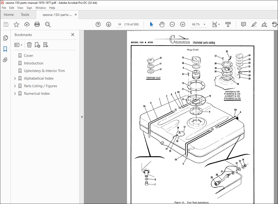
Fig 12. Fuel Tank Installation……………………………….116
Fig 13. Extended Range Fuel Tank Installation………………….118
Fig 14. Fuel Tank Drain Valve Installation…………………….121
Fig 15. Aileron Installation…………………………………122
Fig 16. Flap Installation……………………………………124
Fig 17. Wing Strut Installation………………………………126
Fig 18. Stabilizer Installation………………………………128
Fig 19. Stabilizer Installation – Aerobat……………………..132
Fig 19A. Elevator Trim Tab Actuator Assembly…………………..135
Fig 20. Elevator Installation………………………………..136
Fig 21. Fin Installation…………………………………….140
Fig 21A. Fin Installation……………………………………142
Fig 22. Rudder Assembly……………………………………..144
Fig 22A. Rudder Assembly…………………………………….146
Fig 23. Fuselage Assembly……………………………………148
Fig 24. Fuselage Front & Center Section Assembly……………….150
Fig 24A. Fuselage Front & Center Section Assembly………………154
Fig 25. Main Landing Gear Bulkhead Assembly……………………158
Fig 25A. Main Landing Gear Bulkhead Assembly…………………..160
Fig 26. Fuselage Front Section Assembly……………………….164
Fig 26A. Fuselage Front Section Assembly………………………168
Fig 27. Front Doorpost Bulkhead Assembly………………………172
Fig 28. Front Doorpost Bulkhead Assembly – Aerobat……………..174
Fig 29. Fuselage Tailcone Assembly……………………………176
Fig 30. Aft Tailcone Assembly………………………………..182
Fig 31. Windshield Installation………………………………184
Fig 32. Nose Gear Installation……………………………….186
Fig 33. Nose Gear Strut Assembly……………………………..188
Fig 34. Nose Gear Wheel Assembly……………………………..191
Fig 34A. Nose Gear Wheel Assembly…………………………….192
Fig 34B. Nose Gear Wheel & Tire Assembly………………………194
Fig 34C. Nose Gear Wheel & Tire Assembly………………………195
Fig 35. Shimmy Dampener Assembly……………………………..197
Fig 36. Main Landing Gear Installation………………………..198
Fig 36A. Main Landing Gear Installation……………………….202
Fig 36B. Main Landing Gear Installation……………………….206
Fig 37. Main Gear Wheel & Brake Assembly………………………208
Fig 37A. Main Gear Wheel & Brake Assembly……………………..210
Fig 37B. Main Landing Gear Wheel & Brake Assembly………………214
Fig 38. Cabin Door Installation………………………………216
Fig 38A. Cabin Door Installation……………………………..220
Fig 39. Cabin Door Latch Assembly…………………………….224
Fig 40. Emergency Door Release Installation……………………226
Fig 41. Cabin Top and Firewall Upholstery Installation………….228
Fig 42. Cabin Side Panels & Floorboard Upholstery Installation…..234
Fig 42A. Cabin Side Panels & Floorboard Upholstery Installation….236
Fig 42B. Soundproofing Installation…………………………..239
Fig 43. Seat Installation……………………………………240
Fig 44. Reclining Seat Installation…………………………..242
Fig 44A. Reclining Seat Installation………………………….246
Fig 44B. Reclining Seat Installation………………………….248
Fig 44C. Reclining Seat Installation………………………….252
Fig 44D. Vertical Adjustable Seat Installation…………………254
Fig 45. Reclining Seat Installation – Aerobat………………….258
Fig 45A. Reclining Seat Installation – Aerobat…………………262
Fig 45B. Reclining Seat Installation – Aerobat…………………264
Fig 45C. Reclining Seat Installation – Aerobat…………………268
Fig 45D. Vertical Adjustable Seat Installation – Aerobat………..272
Fig 46. Auxiliary Seat Installation…………………………..274
Fig 47. Instrument Panel Equipment Installation………………..276
Fig 47A. Instrument Panel Equipment Installation……………….284
Fig 47B. Instrument Panel Equipment Installation……………….290
Fig 47C. Instrument Panel Equipment Installation……………….294
Fig 48. Switch Panel Assembly………………………………..300
Fig 48A. Switch Panel Assembly……………………………….302
Fig 48B. Switch & Circuit Breaker Installation…………………304
Fig 48C. Switch & Circuit Breaker Installation…………………306
Fig 49. Glove Box Installation……………………………….308
Fig 49A. Map Case Installation……………………………….310
Fig 50. Fuselage Equipment Installation……………………….312
Fig 50A. Seat Belt & Shoulder Harness Installation……………..316
Fig 50B. Seat Belt & Shoulder Harness Installation……………..320
Fig 51. Compass & Sun Visor Installation………………………324
Fig 51A. Compass & Sun Visor Installation……………………..326
Fig 52. Refueling Step and Handle Installation…………………328
Fig 52A. Static Discharger Installation……………………….330
Fig 53. Propeller and Spinner Installation…………………….332
Fig 53A. Propeller and Spinner Installation……………………334
Fig 54. Winterization Equipment Installation…………………..336
Fig 54A. Winterization Equipment Installation………………….338
Fig 55. Engine Cowl Assembly…………………………………340
Fig 55A. Engine Cowl Assembly………………………………..342
Fig 56. (Sheet 1 of 2) Engine Installation…………………….346
Fig 56. (Sheet 2 of 2) Engine Installation…………………….347
Fig 57A. Oil Cooler Installation……………………………..354
Fig 58. Exhaust Stack Assemblies……………………………..356
Fig 59. Engine Baffles Installation…………………………..358
Fig 59A. Engine Baffles Installation………………………….360
Fig 60. Cabin Heating & Ventilating System Installation…………362
Fig 60A. Cabin Heating & Ventilating System Installation………..366
Fig 61. Rudder & Brake Pedal Installation……………………..368
Fig 62. Master Brake Cylinder Assembly………………………..370
Fig 63. Master Brake Cylinder Assembly………………………..372
Fig 64. Control Y Installation……………………………….374
Fig 65. Rudder Control System Installation…………………….378
Fig 66. Aileron Control System Installation……………………380
Fig 67. Wing Leveler Installation…………………………….384
Fig 68. Wing Leveler Components………………………………386
Fig 69. Electric Flap System Installation……………………..390
Fig 70. Flap Position Indicator Installation…………………..394
Fig 70A. Flap Position Indicator Installation………………….396
Fig 71. Elevator Control System Installation…………………..400
Fig 72. Elevator Trim Control System Installation………………402
Fig 73. Pitot System Installation…………………………….404
Fig 73A. Encoding & Dual Altimeter Installation………………..406
Fig 74. Stall Warning Horn Installation……………………….410
Fig 75. Brake System Installation…………………………….412
Fig 76. Fuel System Installation……………………………..414
Fig 76A. Fuel Shut Off Valve Assembly…………………………418
Fig 77. Fuel Strainer Assembly……………………………….419
Fig 78. Oil System Installation………………………………420
Fig 79. Vacuum System Installation……………………………424
Fig 79A. Vacuum System Installation…………………………..428
Fig 80. Electrical Equipment Installation……………………..432
Fig 81. Instrument Panel Lights Installation…………………..436
Fig 81A. Instrument Panel Lights Installation………………….438
Fig 81B. Instrument Panel Light Installation…………………..440
Fig 82. 60 Amp Alternator Installation………………………..442
Fig 83. Landing Light Installation……………………………444
Fig 84. Landing Light Installation – Cowl……………………..446
Fig 83B. Landing Light Installation – Cowl…………………….448
Fig 84. Flashing Beacon Light Installation…………………….450
Fig 85. Control Wheel Map Light Installation…………………..453
Fig 85A. Control Wheel Map Light & Mike Switch Installation……..454
Fig 86. Floatplane Fittings Installation………………………458
Fig 87. Oil Cooler Installation – Floatplane…………………..460
Numerical Index………………………………………………..463
AN115-21 to AN340B8……………………………………….464
AN340B8 to AN515-8R6………………………………………465
AN515-8R6 to AN6227-5……………………………………..466
AN6227B18 to AN960-10……………………………………..467
AN960-10 to AN960D10L……………………………………..468
AN960D10L to C294501-0101…………………………………..469
C294501-0103 to C664501-0103……………………………….470
C664502-0101 to MS21042L4………………………………….471
MS21042L4 to MS21044N3…………………………………….472
MS21044N3 to NAS1068A4…………………………………….473
NAS1068A4 to NAS43DD3-71…………………………………..474
NAS43DD3-9 to NAS682A06……………………………………475
NAS682A06K to S1021Z8-8……………………………………476
S1021Z8-8 to S1115-19……………………………………..477
S1115-19 to S1485D3U………………………………………478
S1485D3U to S1807-1……………………………………….479
S1810-1075 to S2160-4……………………………………..480
S2160-5 to 0400028-4………………………………………481
0400028-7 to 0405034-16……………………………………482
0405034-17 to 0411144-1……………………………………483
0411174 to 0412020-24……………………………………..484
0412020-25 to 0413202-30…………………………………..485
0413203 to 0413459-1………………………………………486
0413459-2 to 0414009-15……………………………………487
0414009-16 to 0414054-8……………………………………488
0414054-8 to 0422293-1…………………………………….489
0422293-1 to 0426015-1…………………………………….490
0426015-10 to 0431023-1……………………………………491
0431023-1 to 0442017-1…………………………………….492
0442142-1 to 0452112-6…………………………………….493
0452013-2 to 0505061-3…………………………………….494
0505061-4 to 0523233-12……………………………………495
0523233-13 to 0523613-1……………………………………496
0523613-2 to 0713173-6…………………………………….497
0713221-1 to 1205001-92……………………………………498
1205001-92 to 442907-1…………………………………….499
444652 to 9864050-8……………………………………….500
PLEASE NOTE:
- This is the same manual used by the dealers to diagnose and troubleshoot your vehicle
- You will be directed to the download page as soon as the purchase is completed. The whole payment and downloading process will take anywhere between 2-5 minutes
- Need any other service / repair / parts manual, please feel free to contact [email protected] . We still have 50,000 manuals unlisted
S.V


