Kawasaki Wheel Loader 115ZV Circuit Diagram + Workshop Manual + Parts Catalog Manual
File Details:
Kawasaki Wheel Loader 115ZV Circuit Diagram + Workshop Manual + Parts Catalog Manual
Language : English
Pages : 500+
Size : 123 MB
Downloadable : Yes
Format : PDF
Video Preview:

Image Preview:
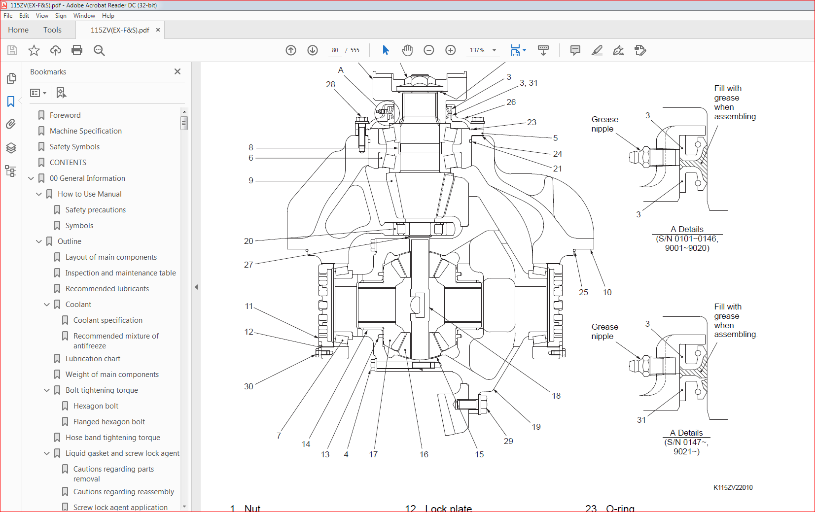
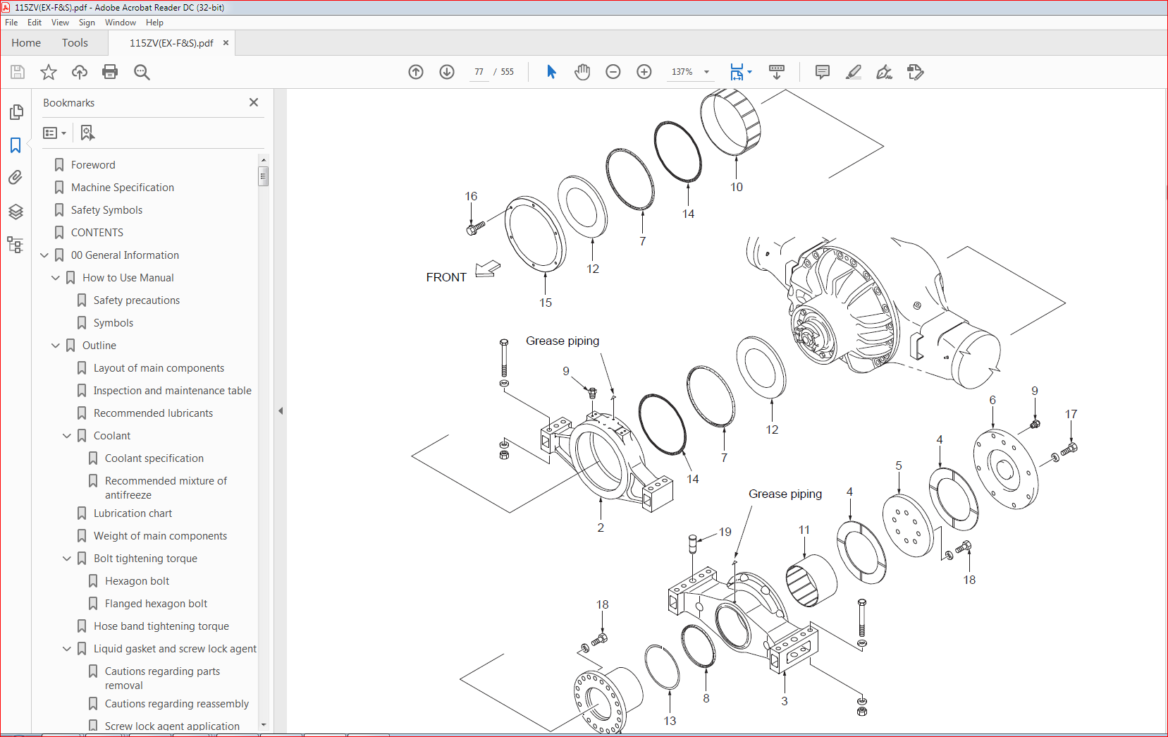
Table of Contents:
Kawasaki Wheel Loader 115ZV Circuit Diagram + Workshop Manual + Parts Catalog Manual
70ZV General Information ……………………………………………………………………………………………………………………. 00-1
How to Use Manual …………………………………………………………………………………………………………………………. 00-2
Safety precautions …………………………………………………………………………………………………………………….. 00-2
Symbols …………………………………………………………………………………………………………………………………… 00-3
Outline …………………………………………………………………………………………………………………………………………… 00-4
Layout of main components ………………………………………………………………………………………………………… 00-4
Inspection and maintenance table ……………………………………………………………………………………………….. 00-5
Recommended lubricants …………………………………………………………………………………………………………… 00-8
Coolant ……………………………………………………………………………………………………………………………………. 00-9
Lubrication chart ……………………………………………………………………………………………………………………… 00-10
Weight of main components ……………………………………………………………………………………………………….00-11
Bolt tightening torque ……………………………………………………………………………………………………………….. 00-12
Hose band tightening torque ……………………………………………………………………………………………………… 00-16
Liquid gasket and screw lock agent ……………………………………………………………………………………………. 00-17
70ZV Measurement for Performance Check …………………………………………………………………………………………… 03-1
Cautions on Safety ………………………………………………………………………………………………………………………….. 03-2
Standard Measurement Values for Performance Check ……………………………………………………………………….. 03-3
70ZV Function & Structure Chassis Group …………………………………………………………………………………………….. 12-1
Front Chassis …………………………………………………………………………………………………………………………………. 12-2
Loading linkage …………………………………………………………………………………………………………………………. 12-2
Loading linkage pin ……………………………………………………………………………………………………………………. 12-4
Rear Chassis …………………………………………………………………………………………………………………………………. 12-5
Floor board mount ……………………………………………………………………………………………………………………… 12-5
Fuel tank (S/N 9001~9005) …………………………………………………………………………………………………………. 12-6
Fuel tank (S/N 9006~) ………………………………………………………………………………………………………………… 12-7
Center Pin ……………………………………………………………………………………………………………………………………… 12-8
Upper center pin ……………………………………………………………………………………………………………………….. 12-8
Lower center pin ……………………………………………………………………………………………………………………….. 12-8
Dust seal ………………………………………………………………………………………………………………………………….. 12-9
70ZV Check & Adjustment Chassis Group …………………………………………………………………………………………….. 13-1
Linkage Pin ……………………………………………………………………………………………………………………………………. 13-2
Liner ………………………………………………………………………………………………………………………………………… 13-2
Center Pin ……………………………………………………………………………………………………………………………………… 13-4
Adjusting shim …………………………………………………………………………………………………………………………… 13-4
Installing bearing cover ………………………………………………………………………………………………………………. 13-4
Installing bearing outer ring …………………………………………………………………………………………………………. 13-5
70ZV Function & Structure Power Group ……………………………………………………………………………………………….. 22-1
Power Line …………………………………………………………………………………………………………………………………….. 22-2
Engine / Transmission ……………………………………………………………………………………………………………………… 22-3
Engine / transmission mount ……………………………………………………………………………………………………….. 22-3
Radiator …………………………………………………………………………………………………………………………………………. 22-4
Radiator mount ………………………………………………………………………………………………………………………….. 22-5
Propeller Shaft ……………………………………………………………………………………………………………………………….. 22-6
Second propeller shaft assembly …………………………………………………………………………………………………. 22-7
Third propeller shaft assembly …………………………………………………………………………………………………….. 22-8
Axle Assembly ………………………………………………………………………………………………………………………………. 22-10
Axle Support …………………………………………………………………………………………………………………………………. 22-12
Differential Gear (TPD) (S/N 9001~9017) …………………………………………………………………………………………. 22-16
Torque Proportioning Differential (S/N 9001~9017) ………………………………………………………………………. 22-19
Operation of T.P.D ……………………………………………………………………………………………………………………. 22-20
Differential Gear (LSD) (S/N 9018~) ………………………………………………………………………………………………… 22-21
Limited Slip Differential (S/N 9018~) …………………………………………………………………………………………… 22-23
70ZV Check & Adjustment Power Group ……………………………………………………………………………………………….. 23-1
Engine …………………………………………………………………………………………………………………………………………… 23-2
Measuring engine speed …………………………………………………………………………………………………………….. 23-2
Measuring engine oil pressure …………………………………………………………………………………………………….. 23-2
Propeller Shaft ……………………………………………………………………………………………………………………………….. 23-3
Propeller shaft phase …………………………………………………………………………………………………………………. 23-3
Second propeller shaft alignment …………………………………………………………………………………………………. 23-3
Tightening torque ………………………………………………………………………………………………………………………. 23-4
Axle ………………………………………………………………………………………………………………………………………………. 23-5
Axle nut tightening procedure ……………………………………………………………………………………………………… 23-5
70ZV Function & Structure Torque Converter and Transmission Group …………………………………………………….. 32-1
Torque Converter ……………………………………………………………………………………………………………………………. 32-2
Torque converter structure ………………………………………………………………………………………………………….. 32-2
Power flow path ………………………………………………………………………………………………………………………… 32-2
Torque multiplication ………………………………………………………………………………………………………………….. 32-2
Torque Converter Gear Pump …………………………………………………………………………………………………………… 32-3
Pump specifications …………………………………………………………………………………………………………………… 32-3
Transmission ………………………………………………………………………………………………………………………………….. 32-4
Clutch combination ……………………………………………………………………………………………………………………. 32-4
Shift lever position ……………………………………………………………………………………………………………………… 32-4
QUAD (Quick up and down shift) …………………………………………………………………………………………………. 32-4
Gear train and number of teeth ……………………………………………………………………………………………………. 32-5
Clutch specifications ………………………………………………………………………………………………………………….. 32-6
Valve location ……………………………………………………………………………………………………………………………. 32-7
Clutch Pack ……………………………………………………………………………………………………………………………………. 32-9
Forward and reverse clutch ………………………………………………………………………………………………………… 32-9
1st and 2nd speed clutch ………………………………………………………………………………………………………….. 32-10
3rd and 4th speed clutch …………………………………………………………………………………………………………….32-11
Power Flow Path in the Transmission ………………………………………………………………………………………………. 32-12
Forward ………………………………………………………………………………………………………………………………….. 32-12
Reverse ………………………………………………………………………………………………………………………………….. 32-16
Hydraulic System Diagram …………………………………………………………………………………………………………….. 32-17
Hydraulic Circuit Diagram ………………………………………………………………………………………………………………. 32-18
Oil Flow ……………………………………………………………………………………………………………………………………….. 32-19
Oil flow in the torque converter line …………………………………………………………………………………………….. 32-19
Oil flow to the clutches ……………………………………………………………………………………………………………… 32-19
T/C and T/M Oil Circulation …………………………………………………………………………………………………………….. 32-20
Control Valve ………………………………………………………………………………………………………………………………… 32-21
Oil port layout ………………………………………………………………………………………………………………………….. 32-22
Modulation Mechanism ………………………………………………………………………………………………………………….. 32-23
Clutch control oil pressure curve ………………………………………………………………………………………………… 32-23
Modulation mechanism operation ………………………………………………………………………………………………. 32-24
Accumulator …………………………………………………………………………………………………………………………………. 32-27
Accumulator for 1st and 2nd speed clutch …………………………………………………………………………………… 32-27
Clutch Solenoid Valve ……………………………………………………………………………………………………………………. 32-28
For forward/reverse and speed clutches ……………………………………………………………………………………… 32-28
70ZV Check & Adjustment Torque Converter and Transmission Group ……………………………………………………… 33-1
Clutch Oil Pressure …………………………………………………………………………………………………………………………. 33-2
Measuring clutch oil pressure ……………………………………………………………………………………………………… 33-2
70ZV Function & Structure Hydraulic Group …………………………………………………………………………………………… 42-1
Flushing Hydraulic Circuit ………………………………………………………………………………………………………………… 42-2
Purpose of flushing ……………………………………………………………………………………………………………………. 42-2
Cautions on Hydraulic Parts Replacement …………………………………………………………………………………………. 42-3
Hydraulic Circuit Symbols ………………………………………………………………………………………………………………… 42-4
Hydraulic lines …………………………………………………………………………………………………………………………… 42-4
Pumps & motors ………………………………………………………………………………………………………………………… 42-4
Cylinders ………………………………………………………………………………………………………………………………….. 42-4
Operation methods …………………………………………………………………………………………………………………….. 42-5
Pressure control valve ………………………………………………………………………………………………………………… 42-5
Flow control valve ……………………………………………………………………………………………………………………… 42-5
Directional control valve ……………………………………………………………………………………………………………… 42-6
Check valve ………………………………………………………………………………………………………………………………. 42-6
Miscellaneous hydraulic symbols …………………………………………………………………………………………………. 42-7
Hydraulic System Operation …………………………………………………………………………………………………………….. 42-8
Hydraulic system operation outline ………………………………………………………………………………………………. 42-8
Layout of Hydraulic Units ……………………………………………………………………………………………………………….. 42-10
Hydraulic Tank ………………………………………………………………………………………………………………………………. 42-11
Hydraulic tank breather valve (tank cap) ……………………………………………………………………………………… 42-14
Hydraulic tank specifications ……………………………………………………………………………………………………… 42-15
Hydraulic oil level check ……………………………………………………………………………………………………………. 42-16
Hydraulic Pump …………………………………………………………………………………………………………………………….. 42-17
Hydraulic pump specifications ……………………………………………………………………………………………………. 42-17
Hydraulic pump principle …………………………………………………………………………………………………………… 42-18
Hydraulic pump wear plate ………………………………………………………………………………………………………… 42-19
Hydraulic pump bushing lubrication ……………………………………………………………………………………………. 42-19
Hydraulic Cylinder …………………………………………………………………………………………………………………………. 42-20
Boom cylinder …………………………………………………………………………………………………………………………. 42-20
Bucket cylinder ………………………………………………………………………………………………………………………… 42-21
Steering cylinder ……………………………………………………………………………………………………………………… 42-22
Hydraulic cylinder specifications ………………………………………………………………………………………………… 42-23
Loading System ……………………………………………………………………………………………………………………………. 42-24
Reducing Valve (for Pilot Pressure) …………………………………………………………………………………………………. 42-25
Pilot Valve (S/N 9001~9030) …………………………………………………………………………………………………………… 42-26
Pilot valve operation …………………………………………………………………………………………………………………. 42-28
Pilot valve (S/N 9031~) ………………………………………………………………………………………………………………….. 42-31
Pilot valve operation …………………………………………………………………………………………………………………. 42-33
Pre-detent and detent magnet solenoid ………………………………………………………………………………………. 42-35
Multiple Control Valve (KML28/2T102) …………………………………………………………………………………………….. 42-36
Multiple control valve specifications ……………………………………………………………………………………………. 42-37
Multiple control valve main relief valve ……………………………………………………………………………………….. 42-38
Multiple control valve overload relief valve (with make-up function) ………………………………………………… 42-40
Multiple control valve make-up valve ………………………………………………………………………………………….. 42-42
Multiple control valve bucket spool …………………………………………………………………………………………….. 42-43
Multiple control valve boom spool ………………………………………………………………………………………………. 42-45
Adapter (Orifice) ……………………………………………………………………………………………………………………………. 42-48
Vibration Damper (OPT) ………………………………………………………………………………………………………………… 42-49
Vibration damper hydraulic circuit ………………………………………………………………………………………………. 42-49
Vibration damper function …………………………………………………………………………………………………………. 42-50
Vibration damper operation ……………………………………………………………………………………………………….. 42-50
Vibration Damper (D/D) Valve Assembly ………………………………………………………………………………………….. 42-51
Solenoid valve (for vibration damper) …………………………………………………………………………………………. 42-53
Accumulator (for vibration damper) …………………………………………………………………………………………….. 42-54
Steering System ……………………………………………………………………………………………………………………………. 42-55
Orbitrol® ……………………………………………………………………………………………………………………………………….. 42-56
Orbitrol® structure ……………………………………………………………………………………………………………………. 42-56
Orbitrol® specification ……………………………………………………………………………………………………………….. 42-57
Orbitrol® operation …………………………………………………………………………………………………………………… 42-58
Orbitrol® feed-back mechanism operation …………………………………………………………………………………… 42-60
Steering speed and flow rate control …………………………………………………………………………………………… 42-61
Hydraulic pump oil amount and steering force ……………………………………………………………………………… 42-61
Orbit rotor operation principle …………………………………………………………………………………………………….. 42-62
Steering Valve (KVS25-A1.0/A3.0/20) ………………………………………………………………………………………………. 42-63
Steering valve operation …………………………………………………………………………………………………………… 42-65
Steering plunger variable throttle ……………………………………………………………………………………………….. 42-67
Steering valve flow control plunger …………………………………………………………………………………………….. 42-68
Steering valve main relief valve …………………………………………………………………………………………………. 42-69
Steering pilot circuit and its operation …………………………………………………………………………………………. 42-73
Stop Valve ……………………………………………………………………………………………………………………………………. 42-75
Stop valve function …………………………………………………………………………………………………………………… 42-76
Stop valve operation ………………………………………………………………………………………………………………… 42-77
Reducing Valve (for Orbitrol®) …………………………………………………………………………………………………………. 42-78
Steering Line Filter ………………………………………………………………………………………………………………………… 42-79
Secondary Steering ……………………………………………………………………………………………………………………….. 42-80
Secondary steering circuit …………………………………………………………………………………………………………. 42-80
Fan Motor System …………………………………………………………………………………………………………………………. 42-83
Fan Motor Line (S/N 9001~9010) …………………………………………………………………………………………………….. 42-84
Fan motor (GM20W-1T7T8-B70A61L) ………………………………………………………………………………………… 42-86
Valve assembly (for fan motor) ………………………………………………………………………………………………….. 42-87
Solenoid valve (for fan speed control) …………………………………………………………………………………………. 42-91
Fan Motor Line (S/N 9011~) ……………………………………………………………………………………………………………. 42-92
Fan motor (GM20W-1T7T8-K70A61L) ………………………………………………………………………………………… 42-94
Thermo sensing valve ………………………………………………………………………………………………………………. 42-95
Fan motor relief valve assembly ………………………………………………………………………………………………… 42-97
Reversing Fan Motor (OPT) ……………………………………………………………………………………………………………. 42-99
Reversing Fan Motor Line (OPT) …………………………………………………………………………………………………… 42-101
Reversing fan motor (PI-GM25B-1Q23D) ………………………………………………………………………………….. 42-104
Thermo sensing valve (for reversing fan) …………………………………………………………………………………… 42-104
Reversing fan motor valve ………………………………………………………………………………………………………. 42-105
70ZV Check & Adjustment Hydraulic Group …………………………………………………………………………………………… 43-1
Loading/Steering Circuit Relief Valve …………………………………………………………………………………………………. 43-2
Loading circuit relief valve setting pressures …………………………………………………………………………………. 43-2
Steering circuit relief valve setting pressures …………………………………………………………………………………. 43-7
Hydraulic Cylinder …………………………………………………………………………………………………………………………. 43-12
Cylinder natural drift …………………………………………………………………………………………………………………. 43-12
Stop Valve ……………………………………………………………………………………………………………………………………. 43-14
Stop valve adjustment procedure ………………………………………………………………………………………………. 43-14
Fan Revolution (S/N 9001~9010) ……………………………………………………………………………………………………. 43-15
Fan maximum revolution measurement ………………………………………………………………………………………. 43-15
Fan revolution adjustment …………………………………………………………………………………………………………. 43-16
Fan Revolution (S/N 9011~) ……………………………………………………………………………………………………………. 43-17
Fan maximum revolution measurement ………………………………………………………………………………………. 43-17
Fan revolution adjustment …………………………………………………………………………………………………………. 43-18
70ZV Function & Structure Brake Group ……………………………………………………………………………………………….. 52-1
Brake System Outline ……………………………………………………………………………………………………………………… 52-2
Service brake ……………………………………………………………………………………………………………………………. 52-2
Parking brake ……………………………………………………………………………………………………………………………. 52-2
Adjustment of axle internal pressure …………………………………………………………………………………………….. 52-2
Brake Units Layout ………………………………………………………………………………………………………………………….. 52-3
Unloader Valve ……………………………………………………………………………………………………………………………….. 52-4
Unloader valve operation ……………………………………………………………………………………………………………. 52-5
Valve Unit ………………………………………………………………………………………………………………………………………. 52-6
Brake Accumulator Line …………………………………………………………………………………………………………………… 52-7
Accumulator ……………………………………………………………………………………………………………………………… 52-8
Reducing valve (for accumulator circuit) ……………………………………………………………………………………….. 52-9
In-Line Filter ……………………………………………………………………………………………………………………………. 52-10
Brake Valve ……………………………………………………………………………………………………………………………………52-11
Brake main valve (left pedal) ………………………………………………………………………………………………………52-11
Brake pilot valve (right pedal) ……………………………………………………………………………………………………. 52-12
Brake valve performance chart ………………………………………………………………………………………………….. 52-13
Brake valve outline …………………………………………………………………………………………………………………… 52-14
Stop lamp pressure switch ………………………………………………………………………………………………………… 52-16
Pressure switch (for Declutch) …………………………………………………………………………………………………… 52-17
Service Brake ……………………………………………………………………………………………………………………………….. 52-18
Service brake operation ……………………………………………………………………………………………………………. 52-18
Service brake friction plate ………………………………………………………………………………………………………… 52-19
Parking Brake ……………………………………………………………………………………………………………………………….. 52-22
Parking brake operation ……………………………………………………………………………………………………………. 52-23
Parking brake solenoid valve …………………………………………………………………………………………………….. 52-24
Parking Brake Manual Release ……………………………………………………………………………………………………….. 52-25
Parking Brake Spring Chamber ……………………………………………………………………………………………………….. 52-27
Brake Circuit Check Valve ………………………………………………………………………………………………………………. 52-28
70ZV Check & Adjustment Brake Group ………………………………………………………………………………………………… 53-1
Brake Circuit Oil Pressure ………………………………………………………………………………………………………………… 53-2
Unloader valve setting pressure …………………………………………………………………………………………………… 53-2
Brake valve oil pressure ……………………………………………………………………………………………………………… 53-6
Service Brake …………………………………………………………………………………………………………………………………. 53-8
Service brake performance check ………………………………………………………………………………………………… 53-8
Service brake friction plate wear measurement ……………………………………………………………………………… 53-9
Cautions on installing brake discs ………………………………………………………………………………………………. 53-10
Parking Brake ……………………………………………………………………………………………………………………………….. 53-11
Parking brake performance check ……………………………………………………………………………………………… 53-11
Parking brake clearance adjustment …………………………………………………………………………………………… 53-13
70ZV Function & Structure Electrical Group …………………………………………………………………………………………… 62-1
How to Use Electrical Wiring Diagram ……………………………………………………………………………………………….. 62-2
Utilisation des schémas des câblages électriques (FRANÇAIS) ……………………………………………………………. 62-3
Verwendung des elektrischen Schaltplans (DEUTSCH) ……………………………………………………………………….. 62-4
Modalità di utilizzo dello schema dei collegamenti elettrici (ITALIANO) …………………………………………………… 62-5
Cómo utilizar un Diagrama de Alambrado Eléctrico (ESPAÑOL) …………………………………………………………… 62-6
Como Utilizar o Diagrama de Ligações Eléctricas (PORTUGUÊS) ………………………………………………………… 62-7
Electrical Cable Color Codes ……………………………………………………………………………………………………………. 62-8
Electrical Circuit Symbols …………………………………………………………………………………………………………………. 62-9
Sensor Mount ……………………………………………………………………………………………………………………………….. 62-10
Fuse ……………………………………………………………………………………………………………………………………………. 62-11
Fuse box ………………………………………………………………………………………………………………………………… 62-12
Fusible link ……………………………………………………………………………………………………………………………… 62-13
Engine Start Circuit ……………………………………………………………………………………………………………………….. 62-15
Engine start circuit diagram ………………………………………………………………………………………………………. 62-15
Neutral starter …………………………………………………………………………………………………………………………. 62-15
Starter switch ………………………………………………………………………………………………………………………….. 62-16
Battery relay ……………………………………………………………………………………………………………………………. 62-17
Alternator I(R) terminal wire ………………………………………………………………………………………………………. 62-17
Diode unit ……………………………………………………………………………………………………………………………….. 62-18
Neutral relay ……………………………………………………………………………………………………………………………. 62-18
Magnet switch …………………………………………………………………………………………………………………………. 62-19
Voltage relay …………………………………………………………………………………………………………………………… 62-19
Power Generating/Charging Circuit …………………………………………………………………………………………………. 62-20
Alternator ……………………………………………………………………………………………………………………………….. 62-20
ECM (Engine Controller) ………………………………………………………………………………………………………………… 62-21
Function of ECM ……………………………………………………………………………………………………………………… 62-21
Connection diagram …………………………………………………………………………………………………………………. 62-21
Monitor lamp test …………………………………………………………………………………………………………………….. 62-22
Failure diagnosis ……………………………………………………………………………………………………………………… 62-23
Quantum fault code information …………………………………………………………………………………………………. 62-29
Accelerator pedal …………………………………………………………………………………………………………………….. 62-36
Accelerator pedal …………………………………………………………………………………………………………………….. 62-38
Transmission Control Circuit and Monitor Circuit ……………………………………………………………………………….. 62-40
Controller ……………………………………………………………………………………………………………………………….. 62-40
Controller connection diagram …………………………………………………………………………………………………… 62-43
Controller function ……………………………………………………………………………………………………………………. 62-44
Monitoring system ……………………………………………………………………………………………………………………. 62-57
Instrument Panel and Switch ………………………………………………………………………………………………………….. 62-59
Instrument panel ……………………………………………………………………………………………………………………… 62-59
Instrument panel rear surface ……………………………………………………………………………………………………. 62-60
Gauge circuit …………………………………………………………………………………………………………………………… 62-61
Electrical Detent Circuit ………………………………………………………………………………………………………………….. 62-63
Bucket leveler …………………………………………………………………………………………………………………………. 62-63
Boom kick-out …………………………………………………………………………………………………………………………. 62-64
Detent solenoid ……………………………………………………………………………………………………………………….. 62-65
Diode …………………………………………………………………………………………………………………………………………… 62-66
Diode check method ………………………………………………………………………………………………………………… 62-67
Caution for diode check method ………………………………………………………………………………………………… 62-67
Surge voltage and surge suppression diodes ………………………………………………………………………………. 62-69
Diagnostic System ………………………………………………………………………………………………………………………… 62-70
Diagnostic system flow ……………………………………………………………………………………………………………… 62-70
Diagnostic failure history memory data ……………………………………………………………………………………….. 62-71
Diagnostic failure history indication and deletion ………………………………………………………………………….. 62-75
Diagnostic switch …………………………………………………………………………………………………………………….. 62-77
70ZV Check & Adjustment Electrical Group ……………………………………………………………………………………………. 63-1
Cautions Regarding Electric Circuit Check …………………………………………………………………………………………. 63-2
Disconnecting or reinstalling connector ………………………………………………………………………………………… 63-2
How to attach the probes of the circuit tester …………………………………………………………………………………. 63-4
Electrical Transmission Control System Troubleshooting Flowchart ……………………………………………………….. 63-5
Standard troubleshooting flowchart ………………………………………………………………………………………………. 63-5
Transmission Controller Abnormal Operation Judgment ………………………………………………………………………. 63-6
Transmission controller check ……………………………………………………………………………………………………… 63-6
Electrical Circuit Check ………………………………………………………………………………………………………………….. 63-10
Shift lever input electrical circuit check ……………………………………………………………………………………….. 63-10
Inching (Declutch) input electrical circuit check ……………………………………………………………………………. 63-12
QUAD switch input electrical circuit check …………………………………………………………………………………… 63-14
Machine speed sensor input electrical circuit check ……………………………………………………………………… 63-15
Clutch solenoid valve output electrical circuit check ……………………………………………………………………… 63-16
Neutral relay electrical circuit check ……………………………………………………………………………………………. 63-19
Parking brake electrical circuit check ………………………………………………………………………………………….. 63-20
Gauge circuit electrical circuit check …………………………………………………………………………………………… 63-22
Bucket positioner electrical circuit check ……………………………………………………………………………………… 63-24
70ZV Function & Structure Operator Station Group …………………………………………………………………………………. 72-1
Cabin …………………………………………………………………………………………………………………………………………….. 72-2
Glass ……………………………………………………………………………………………………………………………………….. 72-3
Wiper mount ……………………………………………………………………………………………………………………………… 72-6
Wiper motor ………………………………………………………………………………………………………………………………. 72-7
Operator Seat …………………………………………………………………………………………………………………………………. 72-9
Steering and Transmission Shift Lever …………………………………………………………………………………………….. 72-10
Tilt case ……………………………………………………………………………………………………………………………………72-11
Column shaft …………………………………………………………………………………………………………………………… 72-12
Shift lever ……………………………………………………………………………………………………………………………….. 72-12
Air Conditioner ……………………………………………………………………………………………………………………………… 72-13
Air conditioner components ………………………………………………………………………………………………………. 72-13
Air conditioner structure ……………………………………………………………………………………………………………. 72-14
Cooling mechanism …………………………………………………………………………………………………………………. 72-19
Cooling circuit …………………………………………………………………………………………………………………………. 72-22
Electrical circuit ……………………………………………………………………………………………………………………….. 72-23
Air conditioner functions of components ……………………………………………………………………………………… 72-24
Charge of refrigerant ………………………………………………………………………………………………………………… 72-52
Air conditioner troubleshooting ………………………………………………………………………………………………….. 72-70
70ZV Check & Adjustment Operator Station Group …………………………………………………………………………………. 73-1
Air Conditioner ……………………………………………………………………………………………………………………………….. 73-2
Adjustment of lubricating oil quantity when components of air conditioner are replaced ………………………. 73-2
Adjustment of air gap (between hub and rotor) in compressor magnetic clutch ………………………………….. 73-5
Compressor V-belt adjustment …………………………………………………………………………………………………….. 73-6
Parts to be replaced periodically ………………………………………………………………………………………………….. 73-7
70ZV Cross-section drawing & Diagrams ………………………………………………………………………………………………. 92-1
Axle Assembly ……………………………………………………………………………………………………………………………….. 92-2
Torque Converter and Transmission ………………………………………………………………………………………………….. 92-3
Loading/Steering Hydraulic Line (S/N 9001~9010) ………………………………………………………………………………. 92-4
Loading/Steering Hydraulic Line (S/N 9011~) ……………………………………………………………………………………… 92-5
Brake Circuit (S/N 9001~9010) …………………………………………………………………………………………………………. 92-6
Brake Circuit (S/N 9011~) ………………………………………………………………………………………………………………… 92-7
Electrical Wiring Diagram (1/2) (S/N 9001~9010) ………………………………………………………………………………… 92-8
Electrical Wiring Diagram (2/2) (S/N 9001~9010) ………………………………………………………………………………… 92-9
Electrical Wiring Diagram (1/2) (S/N 9011~9017) ………………………………………………………………………………. 92-10
Electrical Wiring Diagram (2/2) (S/N 9011~9017) ………………………………………………………………………………..92-11
Electrical Wiring Diagram (1/2) (S/N 9018~9030) ………………………………………………………………………………. 92-12
Electrical Wiring Diagram (2/2) (S/N 9018~9030) ………………………………………………………………………………. 92-13
Electrical Wiring Diagram (1/2) (S/N 9031~) ……………………………………………………………………………………… 92-14
Electrical Wiring Diagram (2/2) (S/N 9031~) ……………………………………………………………………………………… 92-15
Electrical wiring diagram abbreviation chart ………………………………………………………………………………………. 92-16
Electrical Wiring Diagram (CAB) ……………………………………………………………………………………………………… 92-17
Electrical Connection Diagram (S/N 9001~9010) ………………………………………………………………………………. 92-20
Electrical Connection Diagram (S/N 9011~) ………………………………………………………………………………………. 92-21
Electrical Wiring (Reversal Fan) (OPT) …………………………………………………………………………………………….. 92-22
Electrical Equipment Layout ……………………………………………………………………………………………………………. 92-23
Electrical Circuit Diagram (Cabin Air Conditioner) ……………………………………………………………………………… 92-32
Electrical Wiring Diagram (Cabin Air Conditioner) ……………………………………………………………………………… 92-33
Equipment Operation Table (Cabin Air Conditioner) …………………………………………………………………………… 92-34
Description:
Kawasaki Wheel Loader 115ZV Circuit Diagram + Workshop Manual + Parts Catalog Manual
- To ensure good machine performance, reduce failures or problems, and prolong the service life of each component, it is necessary to operate the machine as is directed in the Operator and Maintenance Manual.
- To effectively diagnose and repair the machine, it is important to follow the guidelines laid out in this Shop Manual. Disassembly & Reassembly Service Standard For the engine, refer to the engine Shop Manual provided by the engine manufacturer.
- The purpose of this manual is to provide information on the product and the correct maintenance and repair methods. Please read this manual to ensure correct troubleshooting and good repair service. This manual will be periodically reviewed and revised for more satisfactory content. If you have any opinion or requests, please inform us.
Please Note:
- This is the SAME exact manual used by your dealers to fix your vehicle.
- The same can be yours in the next 2-3 mins as you will be directed to the download page immediately after paying for the manual.
- Any queries / doubts regarding your purchase, please feel free to contact [email protected]