

1963 – 1970 CESSNA 150 & F150 Illustrated Parts Catalog Manual
FILE DETAILS:
1963 – 1970 CESSNA 150 & F150 Illustrated Parts Catalog Manual
Language : English
Pages : 486
Downloadable : YES
Format : PDF
Size : 40.9 MB
DESCRIPTION:
1963 – 1970 CESSNA 150 & F150 Illustrated Parts Catalog Manual
INTRODUCTION:
This illustrated parts analog has been prepared to aid you in easily and quickly identifying parts of the models covered herein. This catalog features an index system consisting of:
- An alphabetiuil index located in the front of the catalog.
- A numerical index located in the back of the catalog, which lists all parts and figures in which they appear.
STANDARD PARTS:
Many parts having standard usage have been incorpo- rated into the Cessna Standard System. Parts in this group are designated with the part number prefix “8-” and are described with the phrase “Cessna Standard” in the nomenclature. For standard hardware items such as Tinnerman nuts, clamps, etc. , “AN” and “NAS” numbers have been used. The vendors number also appears in the de- scription column to aid in identifying the correct part.
TABLE OF CONTENTS:
1963 – 1970 CESSNA 150 & F150 Illustrated Parts Catalog Manual
Cover 1
List of Effective Pages 2
Revision – 10/15/70 3
Introduction 5
Upholstery & Interior Trim 17
Alphabetical Index 25
Parts Listing / Figures 47
Fig 1 Miscellaneous Bulk Items 50
Fig 1A Placards & Nameplates Installation 52
Fig 1B (Sheet 1 of 3) Placards, Nameplates & Exterior Markings 56
Fig 1B (Sheet 2 of 3) Placards, Nameplates & Exterior Markings 57
Fig 1B (Sheet 3 of 3) Placards, Nameplates & Exterior Markings 58
Fig 1C Wing Assembly Complete 60
Fig 1D Patroller Wing Assembly Complete 64
Fig 2 Wing Structure Assembly 68
Fig 2A Patroller Wing Structure Assembly 72
Fig 3 Wing Leading Edge Assembly 78
Fig 4 Fuel Tank Installation 80
Fig 4A Patroller Wing Fuel Tank Installation 82
Fig 4B Fuel Tank Drain Valve Installation 84
Fig 5 Aileron Installation 86
Fig 6 Flap Installation 88
Fig 7 Wing Strut Assembly 91
Fig 7A Wing Strut Assembly 92
Fig 8 Stabilizer and Elevator Installation 96
Fig 9 Vertical Fin, Rudder and Dorsal Installation 100
Fig 9A Fin Installation 104
Fig 9B Rudder Installation 106
Fig 10 Fuselage Assembly 108
Fig 10A Fuselage Assembly 110
Fig 10B Fuselage Assembly 112
Fig 11 Fuselage Front and Center Section Assembly 114
Fig 11A Front & Center Section – Fuselage 118
Fig 11B Landing Gear Bulkhead Assembly 122
Fig 12 Fuselage Front Section Assembly 124
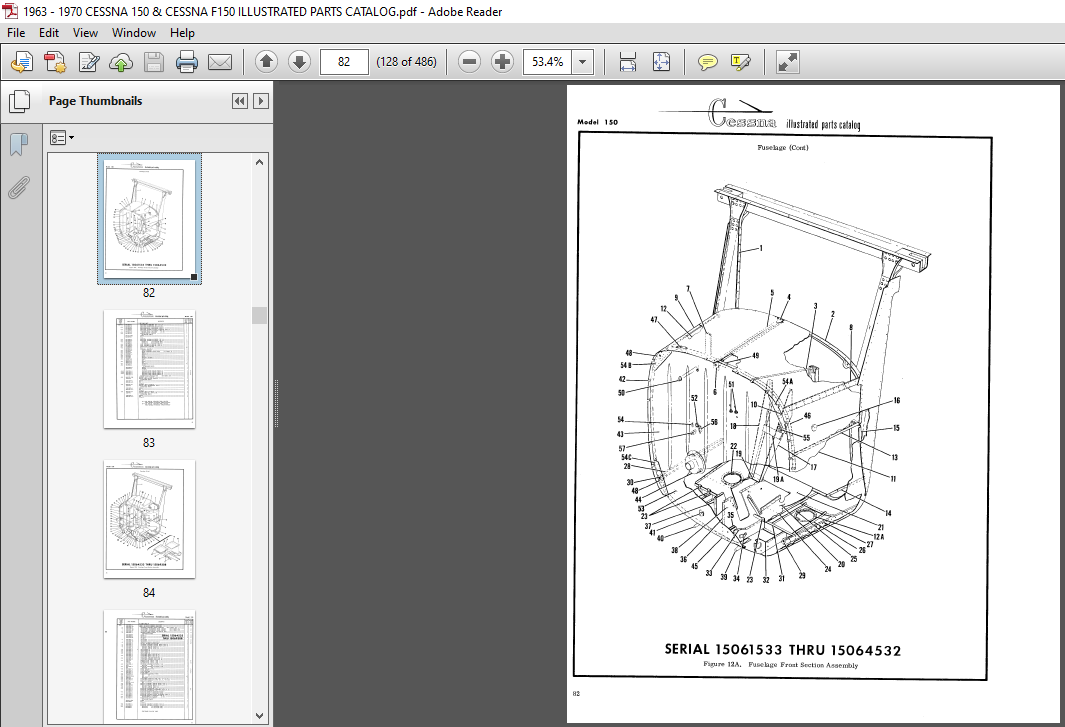
Fig 12A Fuselage Front Section Assembly 128
Fig 12B Fuselage Front Section Assembly 130
Fig 12C Fuselage Front Section Assembly 134
Fig 13 Front Doorpost Bulkhead Assembly 138
Fig 13A Front Doorpost Bulkhead Assembly 140
Fig 14 Fuselage Tailcone Assembly 142
Fig 14A Fuselage Tailcone Assembly 146
Fig 14B Fuselage Tailcone Assembly 148
Fig 14C Aft Tailcone Assembly 152
Fig 15 Windshield Installation 155
Fig 15A Message Drop Tube Installation 156
Fig 16 Nose Gear Installation 158
Fig 16A Nose Gear Installation 160
Fig 16B Nose Gear Installation – Heavy Duty 162
Fig 17 Nose Gear Strut Assembly 164
Fig 17A Nose Gear Strut Assembly 168
Fig 17B Heavy Duty Nose Gear Strut Assembly 170
Fig 18 Main Landing Gear Installation 174
Fig 18A Main Landing Gear Installation 176
Fig 18B Main Landing Gear Installation 180
Fig 19 Seat Installation 182
Fig 19A Child Seat Installation 184
Fig 19B Reclining Seat Installation 186
Fig 19C Auxiliary Seat Installation 190
Fig 19D Auxiliary Seat Installation 192
Fig 20 Upholstery Installation 196
Fig 20A Upholstery Installation 200
Fig 20B Upholstery Installation 202
Fig 20C Cabin Top and Firewall Upholstery Installation 206
Fig 20D Cabin Side Panels & Floorboard Upholstery Installation 208
Fig 21 Left Cabin Door Assembly 210
Fig 22 Right Cabin Door Assembly 214
Fig 22A Patroller Door Assembly 218
Fig 22B Cabin Door Installation 222
Fig 22C Cabin Door Installation 226
Fig 22D Cabin Door Latch Assembly 230
Fig 23 Instrument Panel Equipment Installation 232
Fig 23A Instrument Panel Equipment Installation 236
Fig 23B Instrument Panel Equipment Installation 242
Fig 23C Instrument Panel Equipment Installation 246
Fig 23D Instrument Panel Equipment Installation 250
Fig 23E Instrument Panel Equipment Installation 254
Fig 23F Switch Panel Assembly 258
Fig 24 Glove Box Installation 261
Fig 24A Map Case and Door Installation 262
Fig 24B Glove Box Installation 264
Fig 24C Glove Box Installation 266
Fig 25 Fuselage Equipment Installation 268
Fig 25A Fuselage Equipment Installation 272
Fig 25B Compass Installation 274
Fig 25C Compass & Sun Visor Installation 276
Fig 26 Propeller and Spinner Installation 278
Fig 27 Engine Winterization Installation 281
Fig 27A Winterization Equipment Installation 282
Fig 28 Engine Cowl Assembly 284
Fig 28A Engine Cowl Assembly 286
Fig 29 Engine Installation 288
Fig 30 Engine Assembly 292
Fig 31 Engine Exhaust Stacks Assembly 296
Fig 32 Engine Baffles Installation 298
Fig 33 Cabin Heating and Ventilating System Installation 302
Fig 33A Cabin Heating and Ventilating System Installation 304
Fig 33B Cabin Heating & Ventilating System Installation 308
Fig 34 Brake and Rudder Pedal Installation 312
Fig 35 Control Tee Installation 314
Fig 35A Control Y Installation 316
Fig 35B Control Y Installation 320
Fig 36 Rudder Control System Installation 322
Fig 36A Rudder Control System Installation 324
Fig 37 Aileron Control System Installation 326
Fig 37A Aileron Control System Installation 330
Fig 37B Wing Leveler Installation 332
Fig 37C Wing Leveler Components 334
Fig 38 Flap Control System Installation 340
Fig 38A Flap Control System Installation 344
Fig 38B Electric Flap System Installation 346
Fig 38C Flap Position Indicator Installation 350
Fig 39 Elevator Control System Installation 352
Fig 40 Elevator Trim Control System Installation 354
Fig 40A Elevator Trim Control System Installation 356
Fig 40B Elevator Trim Control System Installation 358
Fig 41 Pitot System Installation 360
Fig 41A Stall Warning Horn Installation 364
Fig 42 Brake System Installation 366
Fig 42A Brake System Installation 368
Fig 43 Fuel System Installation 372
Fig 43A Fuel System Installation 376
Fig 43B Fuel Strainer Assembly 379
Fig 44 Oil System Installation 380
Fig 45 Vacuum System Installation 384
Fig 45A Vacuum System Installation 388
Fig 45B Vacuum System Installation 390
Fig 45C Useage Table For C661002-0201 & C661001-0201 Gyros 393
Fig 45D Vacuum System Installation 394
Fig 45E Vacuum System Installation 398
Fig 46 Electrical Equipment Installation 400
Fig 46A Electrical Equipment Installation 404
Fig 46B Instrument Panel Lights Installation 408
Fig 46C 60 Amp Alternator Installation 410
Fig 47 Landing Light Installation 411
Fig 48 Rotating Beacon Installation 412
Fig 48A Flashing Beacon Light Installation 414
Fig 49 Courtesy Light Installation 417
Fig 50 Control Wheel Maplight Installation 418
Fig 51 Main Landing Gear Wheel and Brake Assembly 419
Fig 51A Main Landing Gear Wheel and Brake Assembly 420
Fig 51B Main Landing Gear Wheel & Brake Assembly 6 00×6 422
Fig 51C Main Wheel & Brake Assembly 424
Fig 52 Nose Gear Wheel Assembly 426
Fig 52A Nose Gear Wheel Assembly 428
Fig 52B Nose Gear Wheel Assembly – Heavy Duty 430
Fig 53 Shimmy Dampener Assembly 432
Fig 53A Shimmy Dampener Assembly 434
Fig 54 Master Brake Cylinder Assembly 436
Fig 54A Master Brake Cylinder Assembly 438
Fig 55 Floatplane Fittings Installation 440
Fig 56 Oil Cooler Installation – Floatplane 444
Numerical Index 447
VIDEO PREVIEW OF THE MANUAL:

IMAGES PREVIEW OF THE MANUAL:
PLEASE NOTE:
- This is the same manual used by the dealers to diagnose and troubleshoot your vehicle
- You will be directed to the download page as soon as the purchase is completed. The whole payment and downloading process will take anywhere between 2-5 minutes
- Need any other service / repair / parts manual, please feel free to contact [email protected] . We still have 50,000 manuals unlisted


