

Mustang 2066 2076 2086 Including 2076 (EU) 2086 (EU) Skid-Steer Loaders Operator’s Manual 917083 GP0408 – PDF DOWNLOAD
FILE DETAILS:
Mustang 2066 2076 2086 Including 2076 (EU) 2086 (EU) Skid-Steer Loaders Operator’s Manual 917083 GP0408 – PDF DOWNLOAD
Language : English
Pages : 102
Downloadable : Yes
File Type : PDF
Size: 4.98 MB
DESCRIPTION:
Mustang 2066 2076 2086 Including 2076 (EU) 2086 (EU) Skid-Steer Loaders Operator’s Manual 917083 GP0408 – PDF DOWNLOAD
INTRODUCTION :
This Operator’s Manual gives the owner/operator information about maintaining and servicing 2066, 2076 and 2086, including the 2076 (EU) and 2086 (EU), skid-steer loader models. More importantly, this manual provides an operating plan for safe and proper use of the machine.
- Major points of safe operation are detailed in the Safety chapter of this manual. We ask that you read and understand the contents of this manual completely and become familiar with your new machine before operating it. See your authorized Mustang dealer if you have any questions concerning information in the manual, require extra manuals or for information concerning the availability of manuals in other languages.
- Throughout this manual information is provided set in italic type and introduced by the word Note or Important. Read carefully and comply with those messages – it will improve your operating and maintenance efficiency, help avoid breakdowns and damage, and extend your machine’s life. A manual storage box in the operator’s compartment holds the Operator’s Manual and AEM Safety Manual (also available in Spanish).
- Please return the manuals to this box and keep them with the unit at all times. If this machine is resold, we recommend that these manuals be given to the new owner. The attachments and equipment available for use with this machine have a wide variety of potential applications.
- Read the manual provided with the attachment to learn how to safely maintain and operate the equipment. Be sure the machine is suitably equipped for the type of work to be performed. Do not use this machine for any applications or purposes other than those described in this manual or applicable for approved attachments.
- If the machine is to be used with special attachments or equipment other than those approved by Mustang Manufacturing Company, consult your Mustang dealer. Any person using non-approved attachments or making unauthorized modifications is responsible for the consequences.
- The Mustang dealership network stands ready to provide you with any assistance you may require, including providing genuine Mustang service parts. All service parts should be obtained from your Mustang dealer. Provide complete information about the part and include the model and serial numbers of your machine. Record these numbers in the space provided on the Table of Contents page, as a handy reference.
- Please be aware that Mustang strives to continuously improve its products and reserves the right to make changes and improvements in the design and construction of any part without incurring the obligation to install such changes on any unit previously delivered.
- If this machine was purchased “used,” or if the owner’s address has changed, please provide your Mustang dealer or Mustang Manufacturing Company Service Department with the owner’s name and current address, along with the machine model and serial numbers. This will allow the registered owner information to be updated, so that the owner can be notified directly in case of an important product issue, such as a safety update program.
TABLE OF CONTENTS:
Mustang 2066 2076 2086 Including 2076 (EU) 2086 (EU) Skid-Steer Loaders Operator’s Manual 917083 GP0408 – PDF DOWNLOAD
Notes 4
2066, 2076 and 2086 Skid-Steer Loaders Operator’s Manual 3
All-Tach and Hydraglide are trademarks of Mustang Manufacturing Company, Inc 3
Introduction 5
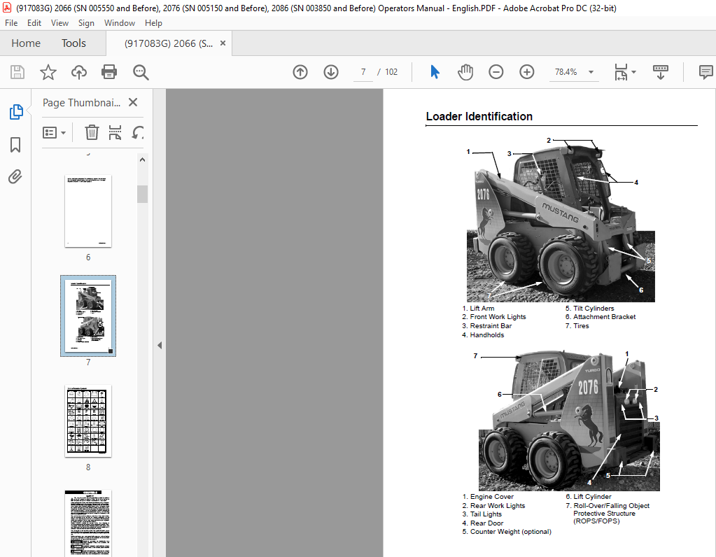
Loader Identification 7
1 Lift Arm 7
2 Front Work Lights 7
3 Restraint Bar 7
4 Handholds 7
5 Tilt Cylinders 7
6 Attachment Bracket 7
7 Tires 7
1 Engine Cover 7
2 Rear Work Lights 7
3 Tail Lights 7
4 Rear Door 7
5 Counter Weight (optional) 7
6 Lift Cylinder 7
7 Roll-Over/Falling Object Protective Structure (ROPS/FOPS) 7
Control/Indicator Symbols 8
Power Off 8
Power On 8
Engine Start 8
Battery Charge 8
al Power 8
Worklight w/Flasher 8
Worklight 8
Safety Alert 8
Hazard Flasher 8
Seatbelt 8
Horn 8
Read Operator’s Manual 8
Volume – Full 8
Volume – Half Full 8
Volume – Empty 8
H-L 8
High – Low 8
N 8
Neutral 8
F 8
Forward 8
R 8
Reverse 8
Parking Brake 8
Engine Air Filter 8
Engine Oil 8
Engine Oil Filter 8
Engine Oil Pressure 8
Fuel Filter 8
Engine Temperature 8
Hydraulic System 8
Hydraulic Oil Temperature 8
Hydraulic Oil Filter 8
Grease Lubrication Point 8
Glow Indicator Lamp 8
Diesel Fuel 8
Chaincase Oil 8
Clockwise Rotation 8
Counterclockwise Rotation 8
Fast 8
Slow 8
Ride Control 8
Engine Malfunction Shutdown 8
Bucket – Float 8
Bucket – Rollback 8
Bucket – Dump 8
Lift Arm – Lower 8
Lift Arm – Raise 8
Service Hours 8
Lift Point 8
Tie-Down 8
Diesel Water Separator 8
Safety 9
Mandatory Safety Shutdown Procedure 10
1 Move the drive control handle(s) to the neutral position 10
2 Lower the lift arm and attachment completely If the lift arm must be left in the raised position, be sure to properly engage the lift arm support device (page 22) 10
3 Move the throttle to the low idle position, shut off the engine and remove the key 10
4 Before exiting, move the lift/tilt control(s) to verify that the controls do not cause movement of the lift arm and hitch 10
Safety Reminders 10
Potential Hazards 12
Safety Decals 12
New Decal Application 12
ANSI-Style Safety Decals inside the ROPS/FOPS 13
ANSI-Style Safety Decals on the outside of the Loader 14
ANSI-Style Safety Decals on the outside of the Loader 15
ANSI-Style Safety Decals in the Engine Compartment 16
ISO-Style (used Internationally) Safety Decals inside the ROPS/FOPS 17
ISO-Style (used Internationally) Safety Decals on the outside of the Loader 18
ISO-Style (used Internationally) Safety Decals on the outside of the Loader 19
ISO-Style (used Internationally) Safety Decals in the Engine Compartment 20
Product and Component Plate Locations 21
Controls and Safety Equipment 23
Guards and Shields 23
Operator Restraint Bar 23
Operator’s Seat 24
Figure 1 Operator’s Seat 24
1 Restraint Bar 24
2 Seatbelt 24
3 Seat Position Adjustment Lever 24
4 Suspension Seat Weight Adjustment Knob (optional) 24
Upper-Torso Restraint 24
Safety Interlock System 24
Hydraloc™ 24
Testing the Safety Interlock System 25
ROPS/FOPS 25
Parking Brake 25
Figure 2 Parking Brake Switch 25
Horn 25
Rear Window Emergency Exit 26
Lift Arm Support Device 26
Engagement 26
Figure 3 Lift Arm Support Device Engaged 26
1 Lower the lift arm fully 26
2 Stop the engine 26
3 Leave the operator’s compartment Remove the lock pin holding the support device up against the lift arm Allow the support device to come down into contact with the lift cylinder 26
4 Return to operator’s compartment and restart the engine 26
5 Use the lift control to raise the lift arm until the support device drops over the end of the lift cylinder and around the cylinder rod Slowly lower the lift arm until the free-end of the support device contacts the top end of the lift cylinder 26
6 Look to make sure the support device is secure against the cylinder end Then, stop the loader engine, remove the key and leave the operator’s compartment 26
Disengagement 27
1 Start the engine; 27
2 Raise the lift arm fully; 27
3 Stop the engine; 27
4 Before leaving the operator’s compartment, check to make sure that the lift arm is being held in the raised position by the solenoid valve (See Note below) 27
Figure 4 Lift Arm Support Device Storage Location 27
5 To store the support device, raise it up until it contacts the lift arm Press in and hold the lock pin button to release its locking mechanism Insert the lock pin through the hole in left arm and through the support device 27
Accessory Plug 27
Dome Light 27
Work Lights 27
Heater (optional) 27
Heater and Air Conditioner (optional) 28
Figure 5 Heater/ Air Conditioner Controls 28
1 Fan Speed: Controls the rate at which air exits the vents 28
2 Heater/Air Conditioner Selector Switch: Turns on either the heater or air conditioner 28
Engine Speed Control 28
Figure 6 Hand Throttle Lever 28
Figure 7 Foot Throttle (T-Bar, Dual-Hand & T-Bar/Joystick control units) 28
Two-Speed Transmission (optional) 29
Hydraglide™ Ride Control System (optional) 29
Auto-Shutdown System 29
Attachment Mounting 29
All-Tach™ Hitch 29
Figure 8 All-Tach™ Hitch 29
Instrument Panels 30
Figure 9 Left Panel 30
Left Panel 30
1 Two-Speed Transmission (optional) – Lights when high speed is engaged 30
2 Parking Brake – Lights when the parking brake is applied 30
3 Fan (optional) – Used to control the fan for the air conditioner and heater 30
4 Heater/Air Conditioner Selector – Used to manually control the heater and air conditioner 30
5 Auxiliary Hydraulic Switch (Detent) (Hand/Foot Models only) – A three-position detented switch use for continuous operation 30
6 Accessory Plug – 12-volt DC power outlet 30
7 Hydraglide™ Ride Control System (optional) – Lights when the ride control system is activated 30
8 Float Indicator (T-bar/Joystick control option only) – Lights when float function is activated 30
9 Parking Brake Switch – Used to manually apply the parking brake 30
Right Panel 31
Figure 10 Right Panel 31
1 Hourmeter – Displays the total operating hours of the loader 31
2 Fuel Level Gauge – Displays the amount of fuel in the tank 31
3 Engine Oil Temperature Gauge – Displays the temperature of the engine oil 31
4 Engine Coolant Temperature – Lights if the engine oil is too hot this warns the operator to stop the engine and determine and correct the cause for the high temperature During normal operation this indicator should be OFF 31
5 Hydraulic Oil Temperature – Lights if the hydraulic oil is too hot This warns the operator to reduce the hydraulic load and determine the cause of the high temperature During normal operation this indicator should be OFF 31
6 Light Switch – Controls all the lights on the loader Symbols denote the four positions of the light switch In a clockwise direction these are: 31
7 Keyswitch – In a clockwise rotation, these positions are: 31
8 Circuit Breakers – Four circuit breakers on the instrument panel protect the loader electrical circuits 32
9 Fasten Seatbelt – A momentary visual (and audible) indicator to remind the operator to fasten the seatbelt(s) 32
10 Engine Oil Pressure – Lights if the engine oil pressure is too low Warns the operator to immediately stop the engine and determine the cause for the low pressure During normal operation this indicator should be OFF 32
11 Battery – Lights if the charging voltage is too high or too low During normal operation this indicator should be OFF 32
12 Preheat Indicator Lamp – Lights when the preheat is active During normal operation this indicator should be OFF 32
T-Bar Controls 33
Figure 11 T-Bar Controls 33
1 Lift/Tilt Control 33
2 Drive Control 33
Drive Controls 33
Lift/Tilt Control 33
T-Bar/Joystick Controls 34
Figure 12 T-Bar/Joystick Controls 34
1 Lift/Tilt Control 34
2 Drive Control 34
Drive Controls 34
Lift/Tilt Control 35
Joystick Controls 36
Figure 13 Joystick Controls 36
1 Lift/Tilt Control 36
2 Drive Control 36
Drive Controls 36
Lift/Tilt Controls 37
Hand/Foot Controls 38
Figure 14 Hand/Foot Controls 38
1 Left Drive Control Handle 38
2 Right Drive Control Handle 38
3 Lift Control Pedal 38
4 Tilt Control Pedal 38
Drive Controls 38
Lift/Tilt Controls 39
Dual-Hand Controls 40
Figure 15 Dual-Hand Controls 40
1 Left Drive/Lift Control 40
2 Right Drive/Tilt Control 40
Drive Controls 40
Lift/Tilt Controls 40
Auxiliary Hydraulic Controls 41
Standard-Flow Auxiliary Hydraulic Control 41
Figure 16 T-Bar, Dual Hand & T-Bar/Joystick Auxiliary Hydraulic Control 41
Figure 17 T-Bar/Joystick Electric Auxiliary Control 41
Figure 18 Hand/Foot Auxiliary Control 41
High-Flow Auxiliary Hydraulic Control (optional) 42
Figure 19 High-Flow Control Lever (T-Bar, Dual-Hand & Hand/Foot controlled units) 42
Figure 20 High-Flow Control Lever (T-Bar/Joystick controlled units) 42
Operation 43
Before Starting the Engine 43
Starting the Engine 43
1 Carefully step up onto the back of the bucket or attachment and grasp the handholds to get into the operator’s compartment 43
2 Fasten the seatbelt(s) and lower the restraint bar 43
3 Verify the following: 43
4 Push the throttle lever forward to approximately half speed 43
5 Turn the key to the START position 43
Cold-Starting 44
Cold-Starting Procedure 44
1 Turn the key to the run position If the preheat light on the right instrument panel comes on, wait until it goes out 44
2 Turn the key switch to the start position 44
3 Repeat if engine does not start 44
Stopping the Loader 44
1 Check that the drive control handle(s) is (are) in neutral position; 44
2 Lower the lift arm and rest the attachment on the ground; 44
3 Pull the throttle lever back to the low idle position (and/or take your foot off the throttle pedal for hands-only control machines); 44
4 Turn the keyswitch to the OFF position and remove the key; and 44
5 Raise the restraint bar, unfasten the seatbelt(s) and grasp the handholds while climbing out of the operator’s compartment 44
Parking the Loader 45
Jump-starting 45
1 Turn the keyswitches of both vehicles to OFF, be sure the vehicles are in “neutral” and NOT touching each other 45
2 Connect the positive (+) jumper cable to the positive (+) battery terminal on the disabled loader first DO NOT allow the positive clamps to touch any metal other than the positive (+) battery terminals 45
3 Connect the other end of the positive jumper cable to the jumper vehicle’s battery positive (+) terminal 45
4 Connect the negative (-) jumper cable to the jumper vehicle’s battery negative (-) terminal 45
5 Make the final negative (-) jumper cable connection to the disabled loader’s engine block or loader frame (ground) – NOT to t 45
6 Start the loader If it does not start at once, start the jumper vehicle engine to avoid excessive drain on the booster battery 45
7 After the disabled loader is started and running smoothly, have the second person remove the jumper cables (negative (-) jump 45
Changing Attachments 46
Connecting Attachments 46
1 Rotate the latch levers until the handles are horizontally out to disengage the lock pins 46
Figure 21 Manual Hitch – disengaged 46
1 Latch Lever 46
2 Latch Pins 46
2 Start the loader engine Be sure the lift arm is lowered and in contact with the loader frame 46
3 Align the loader squarely with the back of the attachment 46
4 Tilt the hitch forward until the top edge of the hitch is below the flange on the back side of the attachment and centered between the vertical plates 46
5 Slowly drive the loader forward and, at the same time, tilt the hitch back to engage the flange on the back side of the attachment 46
6 Stop forward travel when the flange is engaged, but continue to tilt the hitch back to lift the attachment off the ground 46
7 Exercise the Mandatory Safety Shutdown Procedure (page 6) Exit the operator’s compartment and rotate the latch levers to the horizontal position to fully engage the latch pins 46
Connecting Auxiliary Hydraulic Couplings 46
Removing Attachments 47
1 Tilt the hitch back until the attachment is off the ground 47
2 Exercise the Mandatory Safety Shutdown Procedure (page 6) 47
3 Relieve any hydraulic pressure in the auxiliary and attachment lines 47
a Turn the key ON (do not start the engine) 47
b With the restraint bar down, move the auxiliary hydraulic control back and forth This will relieve the pressure in the hydraulic system 47
4 With the engine off, leave the operator’s compartment and disconnect the auxiliary hydraulic hoses 47
5 Rotate the hitch latch levers to the horizontal out position to fully retract the latch pins 47
6 Start the engine and be sure that the lift arm is fully lowered and in contact with the loader frame 47
7 Tilt the hitch forward and slowly back the loader away until the attachment is free from the loader 47
Self-Leveling 47
Using a Bucket 47
Driving over Rough Terrain 47
Driving on an Incline 47
Digging with a Bucket 47
Figure 22 Digging 48
Loading a Bucket 48
Figure 23 Loading 48
Dumping the Load Onto a Pile 48
Dumping the Load Into a Box 49
Figure 24 Dumping Into a Box 49
Dumping the Load Over an Embankment 49
Scraping with a Bucket 49
Figure 25 Scraping 49
Leveling the Ground 49
Figure 26 Leveling the Ground 49
Highway Travel 50
Storing the Loader 50
1 Fully inflate the tires 50
2 Lubricate all grease zerks 50
3 Check all fluid levels and replenish as necessary 50
4 Add stabilizer to the fuel per the fuel supplier’s recommendations 50
5 Remove the battery, charge fully and store in a cool, dry location 50
6 Protect against extreme weather conditions such as moisture, sunlight and temperature 50
Transporting the Loader 50
1 Place blocks at the front and rear of the hauling vehicle’s tires 51
Figure 27 Front Tie-Down 51
2 If the loader has an attachment, lift it slightly off the ground 51
3 Back the loader slowly and carefully up the ramp onto the vehicle 51
4 Lower the loader attachment to the vehicle deck, turn off the engine and remove the key 51
5 Fasten the loader to the hauling vehicle at the points indicated by the tie-down decals (Figure 27 and Figure 28) 51
Figure 28 Rear Tie-Down 51
6 Measure the clearance height of the loader and hauling vehicle Post the clearance height in the cab of the vehicle 51
Lifting the Loader 52
Figure 29 Single-Point Lift Eye 52
1 Using suitable lift equipment, hook into the lift eyes Adjust the length of the slings or chains to lift the loader level 52
Figure 30 ROPS/FOPS Four-Point Lift Eye 52
2 Center the hoist over the ROPS/FOPS To prevent shock loading of the equipment and excessive swinging, slowly lift the loader off the ground Perform all movements slowly and gradually As needed, use a tag line to help position the loader 52
Figure 31 ROPS/FOPS Four-Point Lift Eye 52
Service 53
Dealer Services 53
Replacement Parts 54
Loader Raising Procedure 54
1 To block the loader, obtain enough solid wooden blocks, so that when stacked, all of the tires are raised off the ground 54
Figure 32 Loader Properly Blocked (Tires and wheels removed to show blocks) 54
2 Using a jack or hoist capable of lifting at the fully-equipped weight of the loader (with all attached options), lift the rear of the loader until the rear tires are off the ground 55
3 Stack wooden blocks under the flat part of the loader chassis They should run parallel with, but not touch, the rear tires 55
4 Slowly lower the loader until its weight rests on the blocks If the tires still touch the ground, raise the loader again, add more blocks and lower again 55
5 Repeat Steps 2 through 4 for the front end When the procedure is finished, all four tires are off the ground so they could be removed 55
Loader Lowering Procedure 55
1 Using a jack or hoist, raise the front of the loader until its weight no longer rests on the front blocks 55
2 Carefully remove the blocking under the front of the loader 55
3 Slowly lower the loader until the front tires are resting on the ground 55
4 Repeat Steps 1 through 3 for the rear of the loader When the procedure is finished, all four tires will be on the ground and the blocks removed from under the loader 55
Engine Compartment Access 55
Figure 33 Engine Compartment Access Doors 55
Tilting Back the ROPS/FOPS 56
Figure 34 ROPS/FOPS Lock Mechanism – Engaged 56
Adjustments 56
Control Handles 56
Fuel Sender 56
Engine Speed Control 57
Foreign Material Removal 57
Lubrication 57
Figure 35 Service Locations 59
Chaincases 60
Checking and Adding Oil 60
1 Park the loader on a level surface Stop the engine 60
2 Remove the fill check plug (Figure 36) from each chaincase cover The oil level should be at the plug level or no more than 1/4 in (6 mm) below 60
Figure 36 Fill Plug Location 60
3 If the level is low, add fluid through the fill plug; (Figure 36) until the oil level reaches the check plug hole Reinstall the plugs 60
Draining Oil 60
1 Park the loader on a level surface, or on a sloping surface with the loader facing downhill and the tires blocked 60
Figure 37 Drain Plug 60
2 Remove the drain plug on each chaincase (Figure 37) and drain the oil into a suitable container 60
3 Reinstall and tighten the drain plugs 60
4 Refill the chaincases at the fill plugs 60
Drive Chains 61
Checking Chain Tension 61
1 Raise the loader following the Loader Raising Procedure (page 50) 61
2 Rotate each tire by hand The proper amount of chain defection should be 1/8 in to 1 in (3 to 25 mm) forward and rearward 61
Adjusting Chain Tension 61
1 Raise the loader following the Loader Raising Procedure (page 50) 61
2 Remove the tire from the axle to be adjusted 61
3 Loosen (but DO NOT remove) the bolts holding the axle to the chaincase 61
4 Front Chain Tension – To tighten the front chain, move the front axle assembly toward the front of the loader To loosen the chain, move the front axle assembly toward the rear of the loader 61
5 After proper tension is achieved, retighten the bolts 61
6 Reinstall the tire 61
7 Repeat Steps 2 through 6 for any other axle requiring adjustment 61
8 Lower the loader following the Loader Lowering Procedure (page 51) 61
Engine Air Cleaner 61
Figure 38 Dual-Element Air Cleaner 62
1 Restriction Indicator 62
2 Element Housing 62
3 Mounting Bracket 62
4 Inner Filter Element 62
5 Outer Filter Element 62
6 Element Cover 62
7 Dust Ejector 62
Access 62
1 Open the engine cover and then the rear door (page 51) 62
2 Unlatch the three latches on the air cleaner and remove the cover Clean out any dirt built up in the cover assembly 62
Outer Element 62
1 Carefully pull the outer element out of the housing Never remove the inner element unless it is to be replaced 62
2 Clean out any dirt built up in the housing Leave the inner element installed during this step to prevent debris from entering the engine intake manifold 62
3 Use a trouble light inside the outer element to inspect for bad spots, pinholes or ruptures Replace the outer element if any damage is noted The outer element must be replaced if it is oil- or soot-laden 62
Inner Element 63
Reinstallation 63
1 Check the inside of the housing for any damage that may interfere with the elements 63
2 Be sure that the element sealing surfaces are clean 63
3 Insert the element(s), making sure that they are seated properly 63
4 Secure the cover to the housing with the three clamps 63
5 Check the hose connections and make sure they are all clamped and tightened properly 63
6 Reset the indicator by pressing the reset button 63
Engine Service 64
Figure 39 Engine Service Components 64
1 Air Cleaner 64
2 Muffler 64
3 Fuel Filter 64
4 Engine Oil Fill Cap 64
5 Radiator/Cooler 64
6 Water Separator 64
7 Engine Oil Drain Valve 64
8 Engine Oil Dipstick 64
9 Engine Oil Filte 64
10 Coolant Recovery Tank 64
Checking Engine Mounting Hardware 65
Checking Engine Oil Level 65
Changing Engine Oil and Filter 65
Figure 40 Remote Engine Coolant Drain 65
Changing Fuel Filter 65
Hydraulic System 66
Checking Hydraulic Oil Level 66
Figure 41 Sight Gauge and Fill Tube 66
Changing Hydraulic Oil Filter 66
Figure 42 Hydraulic Oil Filter and Indicator 66
1 Turn off the engine 66
2 Open the reservoir drain plug located on the inside bottom of the right riser 66
3 Drain the oil out to a level below the point where the filter attaches to the reservoir 66
4 Replace the reservoir drain plug 66
5 Spin off the old hydraulic filter element and spin on the new filter element 66
6 Tilt back the ROPS/FOPS 66
7 Refill the hydraulic oil reservoir with oil Refer to the Lubrication chart (page 54) 66
Changing Hydraulic Oil 67
1 Install a catch pan of sufficient capacity under the oil reservoir, see page 53 67
2 Remove the drain plug located on the bottom front of the oil reservoir, behind the right rear tire Allow the oil to drain 67
3 Reinstall the drain plug 67
4 Change the oil filter 67
5 Refill the reservoir Refer to the Lubrication topic (page 53) 67
6 Start the engine and operate the hydraulic controls 67
7 Stop the engine and check for leaks at the filter and reservoir drain plug 67
8 Check the fluid level and add fluid if needed 67
Bucket Cutting Edge 67
Alternator/Fan Belt 67
Wheel Nuts 67
Lift Arm Pivots 67
Cooling System 68
Cleaning the Cooling System 68
Tires 68
Checking Tire Pressure 69
Heater Filters 69
Electrical System 70
Circuit Breakers 70
Battery 70
1 Immediately remove any clothing on which acid spills 70
2 If acid contacts the skin, rinse the affected area with running water for 10 to 15 minutes 70
3 If acid contacts the eyes, flood the eyes with running water for 10 to 15 minutes See a doctor at once Never use any medication or eye drops unless prescribed by the doctor 70
4 To neutralize acid spilled on the floor, use one of the following mixtures: 70
a 1 pound (0 5 kg) of baking soda in 1 gallon (4 L ) of water, or 70
b 1 pint (0 5 L) of household ammonia in 1 gallon (4 L) of water 70
Troubleshooting 71
Maintenance 81
Maintenance Log 82
Maintenance Log 83
Maintenance Log 84
Specifications 85
Loader Specifications 85
Standard Features 87
Optional Features 87
Dimensional Specifications 88
67 5 in (1715 mm), 16 8 ft3 (0 48 m3) Earth & Foundry Bucket w/12 x 16 5 Tires 88
inches 88
mm 88
A 88
160 0 88
4064 88
B 88
123 0 88
3124 88
C 88
81 0 88
2057 88
D 88
129 0 88
3277 88
E 88
39 0o 88
F 88
95 0 88
2413 88
G 88
26 5 88
673 88
J 88
23 0o 88
M 88
90 0o 88
O 88
42 0 88
1067 88
P 88
43 0 88
1095 88
Q 88
67 0 88
1702 88
R 88
67 5 88
1715 88
S 88
8 0 88
203 88
U 88
88 2o 88
V 88
95 5 88
2425 88
W 88
26 0o 88
X 88
79 5 88
2019 88
Y 88
50 6 88
1285 88
75 in (1905 mm), 18 2 ft3 (0 52 m3) Earth & Foundry Bucket 89
w/12 x 16 5 Tires 89
inches 89
mm 89
A 89
160 0 89
4064 89
B 89
123 0 89
3124 89
C 89
81 0 89
2057 89
D 89
134 7 89
3421 89
E 89
39 0o 89
F 89
95 6 89
2428 89
G 89
26 5 89
673 89
J 89
23o 89
M 89
90 0o 89
O 89
42 0 89
1064 89
P 89
48 4 89
1229 89
Q 89
67 0 89
1702 89
R 89
74 8 89
1900 89
S 89
8 0 89
203 89
U 89
89o 89
V 89
101 0 89
2526 89
W 89
25o 89
X 89
83 1 89
2111 89
Y 89
55 2 89
1402 89
Capacities and Ratings 90
2066/2076/2086 (2076 EU/2086 EU) 90
Weight 90
2066/2076 Rating 90
2086 Rating 90
Common Materials and Densities 92
Material 92
Density 92
Bucket Selection 93
Torque Specifications 95
MUSTANG MANUFACTURING COMPANY, INC 96
Warranty 96
MUSTANG WARRANTY SERVICE INCLUDES: 96
MUSTANG WARRANTY DOES NOT INCLUDE: 96
Index 97
IMAGES PREVIEW OF THE MANUAL:

VIDEO PREVIEW OF THE MANUAL:
PLEASE NOTE:
- This is the SAME exact manual used by your dealers to fix your vehicle.
- The same can be yours in the next 2-3 mins as you will be directed to the download page immediately after paying for the manual.
- Any queries / doubts regarding your purchase, please feel free to contact [email protected]
S.V


