

Yanmar INDUSTRIAL DIESEL ENGINE 3 TNV • 4 TNV series (Direct Injection System) SERVICE MANUAL – PDF DOWNLOAD
IMAGES PREVIEW OF THE MANUAL:
DESCRIPTION:
Yanmar INDUSTRIAL DIESEL ENGINE 3 TNV • 4 TNV series (Direct Injection System) SERVICE MANUAL – PDF DOWNLOAD
SAFETY LABELS
Most accidents are caused by negligence of basic safety rules and precautions. For accident
prevention, it is important to avoid such causes before development to accidents.
Please read this manual carefully before starting repair or maintenance to fully
understand safety precautions and appropriate inspection and maintenance
procedures.
Attempting at a repair or maintenance job without sufficient knowledge may cause an unexpected
accident.
It is impossible to cover every possible danger in repair or maintenance in the manual. Sufficient
consideration for safety is required in addition to the matters marked . Especially for
safety precautions in a repair or maintenance job not described in this manual, receive instructions
from a knowledgeable leader.
Safety marks used in this manual and their meanings are as follows:
TABLE OF CONTENTS:
Yanmar INDUSTRIAL DIESEL ENGINE 3 TNV • 4 TNV series (Direct Injection System) SERVICE MANUAL – PDF DOWNLOAD
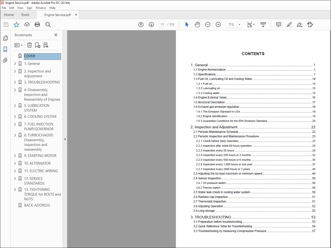
1. General …………………………………………………………………………………………. 1
1.1 Engine Nomenclature ……………………………………………………………………………………………….. 1
1.2 Specifications…………………………………………………………………………………………………………… 1
1.3 Fuel Oil, Lubricating Oil and Cooling Water………………………………………………………………… 14
1.3.1 Fuel oil……………………………………………………………………………………………………………………14
1.3.2 Lubricating oil ………………………………………………………………………………………………………….15
1.3.3 Cooling water ………………………………………………………………………………………………………….15
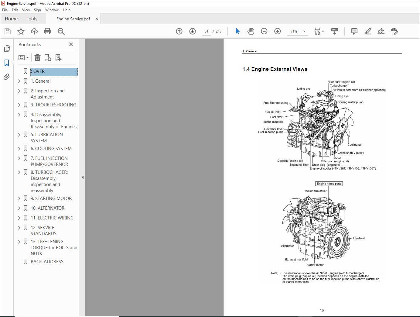
1.4 Engine External Views…………………………………………………………………………………………….. 16
1.5 Structural Description………………………………………………………………………………………………. 17
1.6 Exhaust gas emission regulation………………………………………………………………………………. 18
1.6.1 The Emission Standard in USA ………………………………………………………………………………….18
1.6.2 Engine identification …………………………………………………………………………………………………19
1.6.3 Guarantee Conditions for the EPA Emission Standard…………………………………………………..20
2. Inspection and Adjustment……………………………………………………………… 22
2.1 Periodic Maintenance Schedule ……………………………………………………………………………….. 22
2.2 Periodic Inspection and Maintenance Procedure ………………………………………………………… 23
2.2.1 Check before Daily Operation ……………………………………………………………………………………23
2.2.2 inspection after initial 50 hours operation …………………………………………………………………….25
2.2.3 Inspection every 50 hours …………………………………………………………………………………………28
2.2.4 Inspection every 250 hours or 3 months ……………………………………………………………………..32
2.2.5 Inspection every 500 hours or 6 months ……………………………………………………………………..35
2.2.6 Inspection every 1,000 hours or one year ……………………………………………………………………37
2.2.7 Inspection every 2000 hours or 2 years ………………………………………………………………………46
2.3 Adjusting the no-load maximum or minimum speed…………………………………………………….. 49
2.4 Sensor Inspection…………………………………………………………………………………………………… 50
2.4.1 Oil pressure switch…………………………………………………………………………………………………..50
2.4.2 Thermo switch …………………………………………………………………………………………………………50
2.5 Water leak check in cooling water system………………………………………………………………….. 50
2.6 Radiator cap inspection …………………………………………………………………………………………… 51
2.7 Thermostat Inspection …………………………………………………………………………………………….. 51
2.8 Adjusting Operation ………………………………………………………………………………………………… 52
2.9 Long storage………………………………………………………………………………………………………….. 52
3. TROUBLESHOOTING…………………………………………………………………… 53
3.1 Preparation before troubleshooting …………………………………………………………………………… 53
3.2 Quick Reference Table for Troubleshooting ……………………………………………………………….. 54
3.3 Troubleshooting by measuring Compression Pressure………………………………………………… 57
4. Disassembly, Inspection and Reassembly of Engines………………………… 59
4.1 Complete disassembly and reassembly …………………………………………………………………….. 59
4.1.1 Introduction …………………………………………………………………………………………………………….59
4.1.2 Special service tools…………………………………………………………………………………………………60
4.1.3 Complete disassembly ……………………………………………………………………………………………..65
4.1.4 Precautions before and during reassembly ………………………………………………………………….69
4.1.5 Adjusting operation…………………………………………………………………………………………………..69
4.2 Cylinder Head: Disassembly, Inspection and Reassembly……………………………………………. 70
4.2.1 Components (2-valve cylinder head)…………………………………………………………………………..70
4.2.2 Disassembly procedure:……………………………………………………………………………………………70
4.2.3 Reassembly procedure: ……………………………………………………………………………………………71
4.2.4 Servicing points ……………………………………………………………………………………………………….72
4.2.5 Parts Inspection and measurement…………………………………………………………………………….76
4.2.6 Valve seat correction ………………………………………………………………………………………………..80
4.2.7 Valve guide replacement …………………………………………………………………………………………..81
4.2.8 Valve stem seal replacement……………………………………………………………………………………..82
4.3 Gear Train and Camshaft ………………………………………………………………………………………… 83
4.3.1 Components……………………………………………………………………………………………………………83
4.3.2 Disassembly procedure:……………………………………………………………………………………………83
4.3.3 Reassembly procedure: ……………………………………………………………………………………………83
4.3.4 Servicing points ……………………………………………………………………………………………………….84
4.3.5 Parts inspection and measurement …………………………………………………………………………….87
4.3.6 Oil seal replacement (Gear case side) ………………………………………………………………………..89
4.3.7 Camshaft bushing replacement………………………………………………………………………………….89
4.4 Cylinder Block………………………………………………………………………………………………………… 90
4.4.1 Components……………………………………………………………………………………………………………90
4.4.2 Disassembly procedure:……………………………………………………………………………………………90
4.4.3 Reassembly procedure: ……………………………………………………………………………………………90
4.4.4 Servicing points ……………………………………………………………………………………………………….91
4.4.5 Parts inspection and measurement …………………………………………………………………………….95
4.4.6 Cylinder bore correction ………………………………………………………………………………………….106
4.4.7 Piston pin bushing replacement ……………………………………………………………………………….107
4.4.8 Oil seal replacement (Flywheel housing side) …………………………………………………………….107
5. LUBRICATION SYSTEM ……………………………………………………………… 108
5.1 Lubrication System Diagram ………………………………………………………………………………….. 108
5.2 Trochoid Pump Components ………………………………………………………………………………….. 109
5.3 Disassembly(Reverse the procedure below for assembly) …………………………………………. 109
5.4 Servicing Points……………………………………………………………………………………………………. 109
5.5 Parts Inspection and Measurement…………………………………………………………………………..110
5.5.1 Trochoid pump inspection and measurement……………………………………………………………..110
6. COOLING SYSTEM………………………………………………………………………112
6.1 Cooling Water System…………………………………………………………………………………………….112
6.2 Cooling Water Pump Components ……………………………………………………………………………112
6.3 Disassembly (Reverse the procedure below for assembly) ………………………………………….113
6.4 Servicing Points……………………………………………………………………………………………………..113
7. FUEL INJECTION PUMP/GOVERNOR……………………………………………114
7.1 Introduction ……………………………………………………………………………………………………………114
7.2 Fuel Injection Pump………………………………………………………………………………………………..114
7.2.1 Fuel system diagram………………………………………………………………………………………………114
7.2.2 External view and components…………………………………………………………………………………115
7.2.3 Disassembly procedure:………………………………………………………………………………………….115
7.2.4 Assembly procedure……………………………………………………………………………………………….116
7.2.5 Servicing points ……………………………………………………………………………………………………..116
8. TURBOCHAGER: Disassembly, inspection and reassembly…………………118
8.1 Structure and Functions…………………………………………………………………………………………..118
8.1.1 Main specifications …………………………………………………………………………………………………118
8.1.2 Construction ………………………………………………………………………………………………………….118
8.1.3 Structural and functional outline ……………………………………………………………………………….119
8.1.4 Components………………………………………………………………………………………………………….120
8.2 Service Standards and Tightening Torque………………………………………………………………… 121
8.2.1 Service standards…………………………………………………………………………………………………..121
8.2.2 Tightening torque……………………………………………………………………………………………………122
8.3 Periodic Inspection Procedure………………………………………………………………………………… 123
8.3.1 Periodic inspection intervals …………………………………………………………………………………….123
8.3.2 Inspection procedure………………………………………………………………………………………………124
8.3.3 Waste gate valve adjustment procedure ……………………………………………………………………125
8.4 Disassembly Procedure…………………………………………………………………………………………. 127
8.4.1 Preparation for disassembly…………………………………………………………………………………….127
8.4.2 Inspection before disassembly …………………………………………………………………………………128
8.4.3 Disassembly………………………………………………………………………………………………………….128
8.5 Washing and Inspection procedure …………………………………………………………………………. 130
8.5.1 Washing ……………………………………………………………………………………………………………….130
8.5.2 Inspection procedure………………………………………………………………………………………………131
8.6 Reassembly Procedure …………………………………………………………………………………………. 134
8.6.1 Preparation for reassembly………………………………………………………………………………………134
8.6.2 Reassembly ………………………………………………………………………………………………………….134
8.7 Handling after Disassembly and Reassembly …………………………………………………………… 137
8.7.1 Instructions for turbocharger installation…………………………………………………………………….137
8.8 Troubleshooting ……………………………………………………………………………………………………. 138
8.8.1 Excessively exhaust smoke …………………………………………………………………………………….138
8.8.2 White smoke generation………………………………………………………………………………………….138
8.8.3 Sudden oil decrease……………………………………………………………………………………………….139
8.8.4 Decrease in output …………………………………………………………………………………………………139
8.8.5 Poor (slow) response (starting) of turbocharger ………………………………………………………….139
8.8.6 Abnormal sound or vibration…………………………………………………………………………………….139
9. STARTING MOTOR…………………………………………………………………….. 140
9.1 For 4TNV94L/ 98 ………………………………………………………………………………………………….. 140
9.1.1 Specifications ………………………………………………………………………………………………………..140
9.1.2 Components………………………………………………………………………………………………………….141
9.1.3 Troubleshooting……………………………………………………………………………………………………..142
9.1.4 Names of parts and disassembly procedure ………………………………………………………………143
9.1.5 Inspection and Maintenance ……………………………………………………………………………………147
9.1.6 Service standards…………………………………………………………………………………………………..152
9.1.7 Assembly………………………………………………………………………………………………………………153
9.1.8 Characteristic test…………………………………………………………………………………………………..155
9.2 For 4TNV106(T) …………………………………………………………………………………………………… 156
9.2.1 Specifications ………………………………………………………………………………………………………..156
9.2.2 Congiguration drawing ……………………………………………………………………………………………156
9.2.3 Troubleshooting ……………………………………………………………………………………………………..157
9.2.4 Component names and disassembly procedure …………………………………………………………158
9.2.5 Disassembly procedure…………………………………………………………………………………………..159
9.2.6 Inspection and maintenance ……………………………………………………………………………………167
9.2.7 Assembly………………………………………………………………………………………………………………173
9.2.8 Adjustment ……………………………………………………………………………………………………………174
9.2.9 Service standards…………………………………………………………………………………………………..175
10. ALTERNATOR…………………………………………………………………………… 176
10.1 The 40A Alternator for 3TNV84 and other models……………………………………………………. 176
10.1.1 Components ………………………………………………………………………………………………………..176
10.1.2 Specifications ………………………………………………………………………………………………………177
10.1.3 Wiring diagram …………………………………………………………………………………………………….177
10.1.4 Standard output characteristics ………………………………………………………………………………178
10.1.5 Inspection……………………………………………………………………………………………………………178
10.2 Troubleshooting ………………………………………………………………………………………………….. 179
11. ELECTRIC WIRING …………………………………………………………………… 180
11.1 Electric Wiring Diagram ……………………………………………………………………………………….. 180
11.2 PRECAUTION ON ELECTRIC WIRING…………………………………………………………………. 181
11.2.1 Alternator …………………………………………………………………………………………………………….181
11.2.2 Starter …………………………………………………………………………………………………………………182
11.2.3 Current limiter ………………………………………………………………………………………………………183
11.2.4 Section area and resistance of electric wire ……………………………………………………………..184
12. SERVICE STANDARDS …………………………………………………………….. 185
12.1 Engine Tuning…………………………………………………………………………………………………….. 185
12.2 Engine Body ………………………………………………………………………………………………………. 186
12.2.1 Cylinder head ………………………………………………………………………………………………………186
12.2.2 Gear train and camshaft………………………………………………………………………………………..189
12.2.3 Cylinder block………………………………………………………………………………………………………190
12.3 Lubricating Oil System (Trochoid Pump) ………………………………………………………………… 195
12.3.1 Outside clearance of outer rotor ……………………………………………………………………………..195
12.3.2 Side clearance of outer rotor ………………………………………………………………………………….195
12.3.3 Inside clearance of inner rotor ………………………………………………………………………………..195
12.3.4 Rotor shaft clearance ……………………………………………………………………………………………195
13. TIGHTENING TORQUE for BOLTS and NUTS ……………………………… 196
13.1 Tightening Torques for Main Bolts and Nuts ……………………………………………………………. 196
13.2 Tightening Torques for Standard Bolts and Nuts ……………………………………………………… 197
VIDEO PREVIEW OF THE MANUAL:
PLEASE NOTE:
- This is the SAME exact manual used by your dealers to fix your vehicle.
- The same can be yours in the next 2-3 mins as you will be directed to the download page immediately after paying for the manual.
- Any queries / doubts regarding your purchase, please feel free to contact [email protected]
S.M


