

Arctic Cat 700 Diesel ATV 2010 Workshop Service Repair Manual
FILE DETAILS:
LANGUAGE:ENGLISH
PAGES:180
DOWNLOADABLE:YES
FILE TYPE:PDF
VIDEO PREVIEW OF THE MANUAL:

DESCRIPTION:
Arctic Cat 700 Diesel ATV 2010 Workshop Service Repair Manual
FOREWORD:
- This Arctic Cat Service Manual contains service, maintenance, and troubleshooting information for the 2010 Arctic Cat 700 Diesel SD ATV. The complete manual is designed to aid service personnel in service-oriented applications.
- This manual is divided into sections. Each section covers a specific ATV component or system and, in addition to the standard service procedures, includes disassembling, inspecting, and assembling instructions. When using this manual as a guide, the technician should use discretion as to how much disassembly is needed to correct any given condition.
- The service technician should become familiar with the operation and construction of each component or system by carefully studying the complete manual. This manual will assist the service technician in becoming more aware of and efficient with servicing procedures. Such efficiency not only helps build consumer confidence but also saves time and labor.
- All Arctic Cat ATV publications and decals display specific symbols to emphasize important information. The symbol ! WARNING identifies personal safety-related information. Be sure to follow the directive because it deals with the possibility of severe personal injury or even death. A CAUTION identifies unsafe practices which may result in ATV-related damage. Follow the directive because it deals with the possibility of damaging part or parts of the ATV. The symbol NOTE: identifies supplementary information worthy of particular attention. The symbol AT THIS POINT directs the technician to certain and specific procedures to promote efficiency and to improve clarity.
- At the time of publication, all information, photographs, and illustrations were technically correct. Some photographs used in this manual are used for clarity purposes only and are not designed to depict actual conditions. Because Arctic Cat Inc. constantly refines and improves its products, no retroactive obligation is incurred.
TABLE OF CONTENTS:
Arctic Cat 700 Diesel ATV 2010 Workshop Service Repair Manual
General Specifications 1-2
Torque Specifications 1-2
Tightening Torque (General Bolts) 1-3
Torque Conversions (ft-lb/N-m) 1-3
Break-In Procedure 1-4
Fuel – Oil – Lubricant 1-4
Genuine Parts 1-5
Preparation For Storage 1-5
Preparation After Storage 1-5
Periodic Maintenance Chart 2-2
Periodic Maintenance/Tune-Up 2-3
Lubrication Points 2-3
Battery 2-3
Fuses 2-4
Air Filter 2-4
Valve Clearance 2-5
Muffler/Spark Arrester 2-6
Fuel/Vent Hoses 2-6
Adjusting Throttle Cable 2-6
Engine RPM (Idle) 2-6
Engine Oil – Filter 2-6
Transmission Lubricant 2-8
Front Differential/Rear Drive Lubricant 2-8
Tires 2-9
Steering Components 2-9
Driveshaft/Coupling 2-9
Suspension/Shock Absorbers/Bushings 2-9
Nuts/Cap Screws/Screws/Bolts 2-9
Injector Timing 2-9
Headlight/Taillight-Brakelight 2-10
Switches 2-11
Shift Lever 2-11
Frame/Welds/Racks 2-11
Electrical Connections 2-12
Hydraulic Brake Systems 2-12
Burnishing Brake Pads 2-13
Coolant 2-13
Checking/Replacing V-Belt 2-14
Fuel Filter 2-16
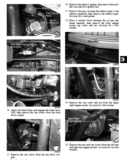
Engine/Transmission 3-2
Specifications 3-2
700 Diesel Table of Contents 3-3
Troubleshooting 3-80
Fuel/Lubrication/Cooling 4-2
Diesel Fuel Injection System 4-2
Lift Pump 4-2
Unit Injectors 4-3
Injector Timing 4-3
Fuel Filter 4-3
Fuel Solenoid Assembly 4-3
Throttle Cable Free-Play 4-4
Fuel Tank 4-4
Fuel/Vent Hoses 4-5
Oil Filter/Oil Pump 4-5
Testing Oil Pump Pressure 4-5
Liquid Cooling System 4-6
Radiator 4-6
Hoses/Thermostat 4-7
Fan 4-7
Water Pump 4-7
Troubleshooting 4-8
Electrical System 5-2
Battery 5-2
Testing Electrical Components 5-2
Accessory Receptacle/Connector 5-2
Brakelight Switch (Auxiliary) 5-2
Brakelight Switch (Handlebar Control) 5-3
Cooling Fan Switch 5-4
Engine Coolant Temperature (ECT)
Switch/Thermistor 5-4
Glow Plug Controller/Relay 5-4
Fan Motor 5-5
Fuse Block/Power Distribution Module 5-6
Fuses 5-6
Electronic Speedometer Speed Sensor 5-6
Ignition Switch 5-7
Handlebar Control Switches 5-7
Drive Select Switch 5-8
Front Drive/Differential Lock Actuator 5-8
Starter/Starter Solenoid 5-9
Starter Relay 5-10
Alternator/Regulator 5-10
Neutral Start/Front Drive Actuator/Start-in-Gear/
Differential Lock/2WD Relays 5-11
Headlights 5-11
Taillight – Brakelight 5-12
Fuel Solenoid 5-12
Troubleshooting 5-13
Drive System 6-2
General Information 6-2
Front Drive Actuator 6-2
Front Differential 6-3
Drive Axles 6-16
Rear Gear Case 6-21
Hub 6-21
Hydraulic Brake Caliper 6-22
Troubleshooting Drive System 6-26
Troubleshooting Brake System 6-26
Suspension 7-2
Shock Absorbers 7-2
Front A-Arms 7-3
Rear A-Arms 7-5
Wheels and Tires 7-7
Troubleshooting 7-8
Steering/Frame 8-2
Steering Post/Tie Rods 8-2
Handlebar Grip 8-4
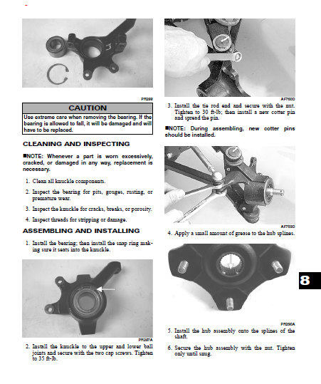
Steering Knuckles 8-4
Measuring/Adjusting Toe-In 8-6
Front Rack 8-8
Front Bumper Assembly 8-8
Front Body Panel/Side Panels 8-8
Footrests 8-11
Belly Panel 8-11
Exhaust System 8-11
Rear Body Panel/Rack 8-12
Adjusting Headlight 8-13
Taillight Assembly 8-13
Seat 8-13
Troubleshooting 8-14
Hand Brake Lever/Master Cylinder Assembly 9-2
Throttle Control 9-3
Shift Lever 9-4
Speedometer/Tachometer/LCD 9-4
IMAGES PREVIEW OF THE MANUAL:

PLEASE NOTE:
- This is not a physical manual but a digital manual – meaning no physical copy will be couriered to you. The manual can be yours in the next 2 mins as once you make the payment, you will be directed to the download page IMMEDIATELY.
- This is the same manual used by the dealers inorder to diagnose your vehicle of its faults.
- Require some other service manual or have any queries: please WRITE to us at [email protected]


Malachi Ellis –