

Sharp Lc 65d64u Service Manual Repair Guide PDF Download
IMAGES PREVIEW:

VIDEO PREVIEW:

DESCRIPTION:
- Sharp Lc 65d64u Service Manual Repair Guide PDF Download
- This service manual is issued since the main and side PWBs used for LC-65D64U have been changed. For the product where the main and side PWBs have been changed, refer to the following serial No. for each model. Model name/Serial No. LC65D64U: 712851112~.
- Service work should be performed only by qualified service technicians who are thoroughly familiar with all safety checks and the servicing guidelines which follow:
TABLE OF CONTENTS:
Sharp Lc 65d64u Service Manual Repair Guide PDF Download
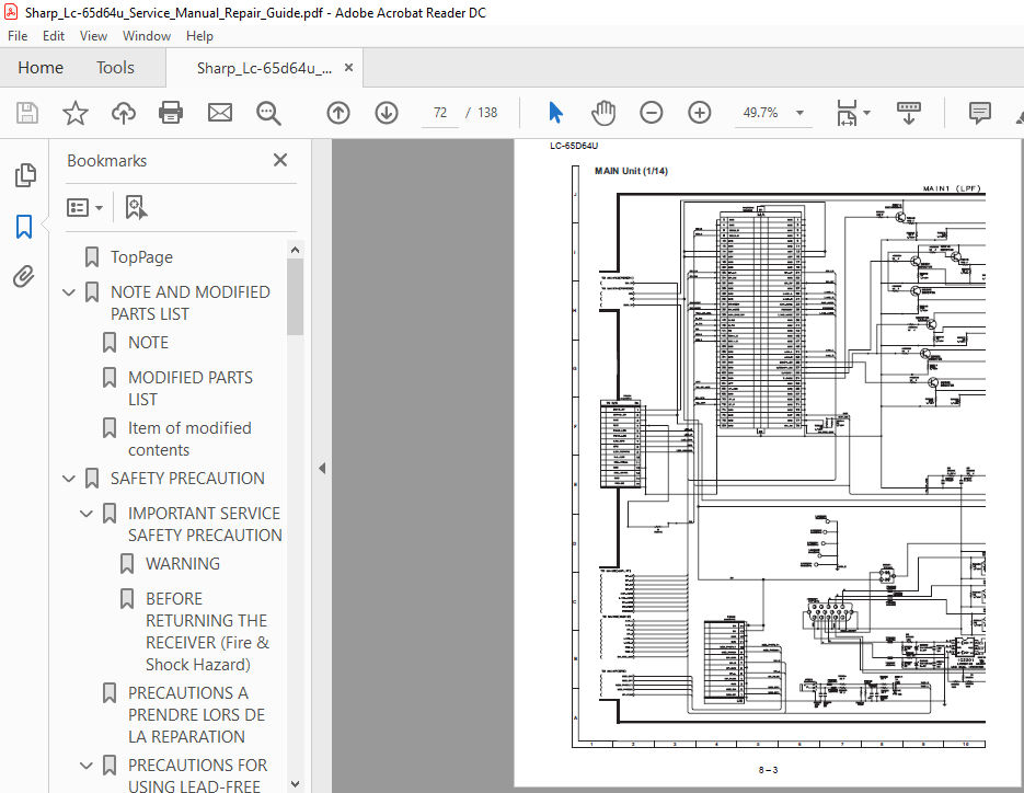
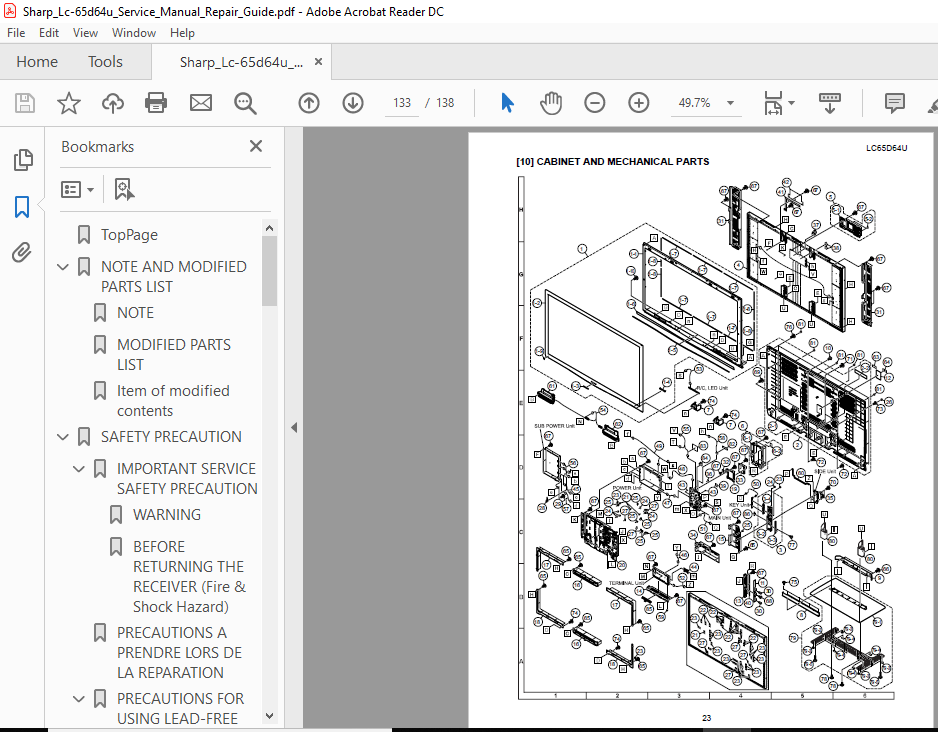
TopPage..............................................................................................  1
NOTE AND MODIFIED PARTS LIST.........................................................................  2
	NOTE.............................................................................................  2
	MODIFIED PARTS LIST..............................................................................  2
	Item of modified contents........................................................................  2
SAFETY PRECAUTION....................................................................................  3
	IMPORTANT SERVICE SAFETY PRECAUTION..............................................................  3
		WARNING......................................................................................  3
		BEFORE RETURNING THE RECEIVER (Fire & Shock Hazard)..........................................  3
	PRECAUTIONS A PRENDRE LORS DE LA REPARATION......................................................  4
	PRECAUTIONS FOR USING LEAD-FREE SOLDER...........................................................  5
		Employing lead-free solder...................................................................  5
		Using lead-free wire solder..................................................................  5
		Soldering....................................................................................  5
	PRECAUTIONS IN SERVICING THE HDCP-KEY ROM........................................................  5
OPERATION MANUAL.....................................................................................  6
	[1] SPECIFICATIONS...............................................................................  6
	[2] OPERATION MANUAL.............................................................................  7
	[3] DIMENSIONS................................................................................... 13
REMOVING OF MAJOR PARTS.............................................................................. 14
	[1] REMOVING OF MAJOR PARTS...................................................................... 14
ADJUSTMENT........................................................................................... 20
	[1] ADJUSTMENT PROCEDURE......................................................................... 20
		1. After replacement of any PWB unit and/or IC for repair, please note the following......... 20
		2. Upgrading of each microprocessor software................................................. 20
		3. Entering and exiting the adjustment process mode.......................................... 23
		4. Remote controller key operation and description of display in adjustment process mode..... 23
		5. List of adjustment process mode menu...................................................... 24
		6. Special features.......................................................................... 29
		7. Video signal adjustment procedure......................................................... 29
		8. Adjustment of white balance............................................................... 31
		9. Initialization to factory settings........................................................ 32
		10. Model number ID plug..................................................................... 33
TROUBLESHOOTING TABLE................................................................................ 34
	[1] TROUBLESHOOTING TABLE........................................................................ 34
MAJOR IC INFORMATIONS................................................................................ 49
	[1] MAJOR IC INFORMATIONS........................................................................ 49
		1. MAJOR IC INFORMATIONS..................................................................... 49
OVERALL WIRING/BLOCK DIAGRAM......................................................................... 52
	[1] OVERALL WIRING DIAGRAM....................................................................... 52
	[2] SYSTEM BLOCK DIAGRAM......................................................................... 54
PRINTED WIRING BOARD ASSEMBLIES...................................................................... 56
	[1] MAIN Unit.................................................................................... 56
	[2] TERMINAL Unit................................................................................ 64
	[3] SIDE Unit.................................................................................... 66
	[4] R/C, LED Unit................................................................................ 68
	[5] KEY Unit..................................................................................... 69
SCHEMATIC DIAGRAM.................................................................................... 70
	[1] DESCRIPTION OF SCHEMATIC DIAGRAM............................................................. 70
		1. VOLTAGE MEASUREMENT CONDITION:............................................................ 70
		2. INDICATION OF RESISTOR & CAPACITOR:....................................................... 70
	[2] SCHEMATIC DIAGRAM............................................................................ 71
PartsGuide...........................................................................................111
	[1] PRINTED WIRING BOARD ASSEMBLIES..............................................................112
	[2] LCD PANEL (NOTE: THE PARTS HERE SHOWN ARE SUPPLIED AS AN ASSEMBLY BUT NOT INDEPENDENTLY.)....112
	[3] DUNTKE558FM01 (MAIN Unit)....................................................................112
	[4] DUNTKE208FM01 (TERMINAL Unit)................................................................125
	[5] DUNTKE488FM01 (SIDE Unit)....................................................................128
	[6] DUNTKE264FM02 (R/C, LED Unit)................................................................130
	[7] DUNTKE266FM02 (KEY Unit).....................................................................130
	[8] NOTE (Conductive cloth tape).................................................................131
	[9] NOTE (Temperature-proof cover)...............................................................132
	[10] CABINET AND MECHANICAL PARTS................................................................133
	[11] SUPPLIED ACCESSORIES........................................................................135
	[12] PACKING PARTS (NOT REPLACEMENT ITEM)........................................................136
	[13] SERVICE JIG (USE FOR SERVICING).............................................................137
	nINDEX...........................................................................................  0
PLEASE NOTE:
- This is not a physical manual but a digital manual – meaning no physical copy will be couriered to you. The manual can be yours in the next 2 mins as once you make the payment, you will be directed to the download page IMMEDIATELY.
- This is the same manual used by the dealers inorder to diagnose your vehicle of its faults.
- Require some other service manual or have any queries: please WRITE to us at [email protected]

Dion Ray –
I like it