

Case SR130 SR250 SR160 SV185 SR175 SV300 Tier 4 Alpha Series Skid Steer Loader TR320 TV380 Tier 4 Alpha Series Compact Track Loader Operator’s Manual 47408100 – PDF DOWNLOAD
IMAGES PREVIEW OF THE MANUAL:
DESCRIPTION:
Case SR130 SR250 SR160 SV185 SR175 SV300 Tier 4 Alpha Series Skid Steer Loader TR320 TV380 Tier 4 Alpha Series Compact Track Loader Operator’s Manual 47408100 – PDF DOWNLOAD
SR160 SV185
SR175 SV300
Tier 4
Alpha Series Skid Steer Loader
TR320
TV380
Tier 4
Alpha Series Compact Track Loader
1st edition English
Note to the Owner:
- This manual contains important information about the safe operation, adjustment, and maintenance of your machine.
Refer to the detailed INDEX at the end of this manual for locating specific items about your machine. Your machine
conforms to current safety regulations. - Use this manual as a guide. Your machine will remain a reliable working tool as long as it is kept in good working
condition and serviced properly. - This machine, with standard equipment and authorized attachments, is intended for above ground material handling.
Use only approved accessories and attachments designed for your machine. - This operators manual is to be stored in the manual compartment equipped on this machine. Make sure this manual
is complete and in good condition. Contact your authorized dealer to obtain additional manuals. Contact your authorized
dealer for any further information or assistance about your machine. Your authorized dealer has manufacturer
approved service parts. - Your authorized dealer has technicians with special training that know the best methods or
repair and maintenance for your machine. Your authorized dealer is available for any further information. They will
also provide any after-sales service you may need, and genuine CASE CONSTRUCTION spare parts, your guarantee
of quality and match. - The information in this manual is provided on the basis of information that was available at the time that the manual
was written. Settings, procedures, part numbers, software, and other items can change. These changes can affect
the service that is given to the machine. Ensure that you have complete and current information from your dealer
before you start any machine operation.
TABLE OF CONTENTS:
Case SR130 SR250 SR160 SV185 SR175 SV300 Tier 4 Alpha Series Skid Steer Loader TR320 TV380 Tier 4 Alpha Series Compact Track Loader Operator’s Manual 47408100 – PDF DOWNLOAD
1 GENERAL INFORMATION
Note to the Owner 1-1
Declaration of conformity 1-3
Electro-Magnetic Compatibility (EMC) 1-6
Right, left, front and rear of the machine 1-7
Product Identification Number (PIN) 1-8
Machine components 1-11
Emissions overview 1-12
2 SAFETY INFORMATION
Signal word definitions 2-1
Safety rules 2-2
Airborne noise emission 2-7
Utility safety 2-9
Proper entry and exit 2-10
Starting and stopping precautions 2-12
Seat belt precautions 2-13
Specific precautions to this machine 2-15
Operating precautions 2-16
Maintenance precautions 2-18
Transporting precautions 2-18
Fuel handling precautions 2-19
Burn prevention 2-19
Fire extinguisher 2-20
Roll Over Protective Structure (ROPS) 2-21
Welding on the machine 2-22
Mechanical lift arm lock procedure – Radial lift machines 2-23
Mechanical lift arm lock procedure – Vertical lift machines 2-25
No engine power – Lift arm down control 2-27
Emergency exit 2-28
Machine safety sign information 2-29
Safety signs 2-30
3 CONTROLS AND INSTRUMENTS
ACCESS TO OPERATOR’S PLATFORM
Door latches, cab 3-1
Window glass, cab 3-2
Windshield wiper and washer controls 3-3
Cab air louvers 3-4
OPERATOR’S SEAT
Standard seat 3-5
Mechanical suspension seat 3-5
Air seat 3-5
Seat belt operation 3-6
Shoulder belt 3-7
Restraint bar 3-7
MECHANICAL HYDRAULIC CONTROLS
Steering and travel 3-8
Moving the machine 3-8
Turning the machine 3-9
Lift arm and bucket controls 3-10
Hand controls 3-10
Foot controls 3-11
ELECTRO-HYDRAULIC CONTROLS
Control pattern overview 3-12
Standard H control pattern 3-12
Standard ISO control pattern 3-13
Electro-hydraulic control handle adjustment 3-13
H control pattern steering and travel 3-14
Left-hand control lever 3-14
Right-hand control lever 3-14
Moving the machine 3-15
Turning the machine 3-16
H control pattern lift arm and bucket controls 3-17
Lift arm raise/lower control 3-17
Bucket curl/dump control 3-18
ISO control pattern steering and travel 3-19
Moving the machine 3-19
Turning the machine 3-20
ISO control pattern lift arm and bucket controls 3-22
Lift arm and bucket controls 3-22
CONTROL HANDLES
Switch configurations 3-23
Two speed function 3-28
AUXILIARY HYDRAULICS
Standard auxiliary hydraulics 3-29
High flow auxiliary hydraulics 3-30
Enhanced High Flow (EHF) auxiliary hydraulics 3-31
INSTRUMENT CLUSTER
Electronic Instrument Cluster (EIC) 3-32
Advanced Instrument Cluster (AIC) 3-37
Instrument cluster 3-42
Left column switch identification 3-61
ISO or H pattern control switch 3-63
Machine lights 3-64
4 OPERATING INSTRUCTIONS
COMMISSIONING THE UNIT
Operating Instructions 4-1
STARTING THE UNIT
Engine operation 4-3
Operating in extreme temperatures 4-5
Throttle control 4-6
STOPPING THE UNIT
Parking the machine and stopping the engine 4-7
Booster battery procedure 4-8
MOVING THE UNIT
Machine operation 4-9
5 TRANSPORT OPERATIONS
SHIPPING TRANSPORT
Transporting the machine 5-1
RECOVERY TRANSPORT
Moving a disabled machine 5-5
6 WORKING OPERATIONS
GENERAL INFORMATION
Mechanical attachment mounting systems 6-1
Hydraulic attachment mounting systems 6-4
Field operation 6-6
7 MAINTENANCE
GENERAL INFORMATION
General safety before you service 7-1
General specification – Biodiesel fuels – Biodiesel fuels 7-3
Lubrication analysis program 7-5
Plastic and resin parts 7-5
Ecology and the environment 7-5
Tilting operator’s compartment forward 7-6
Machine cleaning 7-10
Window removal and cleaning 7-11
Cab door removal and installation 7-13
Battery safety – check and cleaning 7-14
Fire extinguisher 7-16
Engine hourmeter 7-16
Wheels and tires 7-17
Fluids and lubricants 7-19
Engine oil viscosity 7-20
Hydraulic oil viscosity 7-21
Lubrication and maintenance access 7-22
Fuses and relays 7-24
MAINTENANCE CHART
Maintenance Chart 7-28
EVERY 10 HOURS OR DAILY
Clean tracks and components 7-29
Engine and hydraulic coolers 7-30
Engine coolant level 7-31
Engine oil level 7-32
Lift arm, pivot points, coupler pins and cylinder pins 7-33
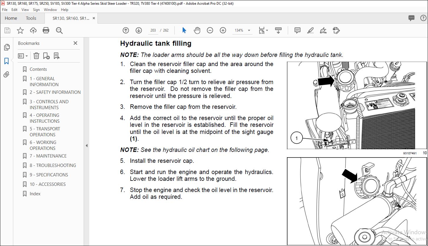
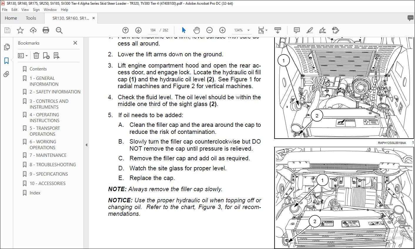
Hydraulic oil level 7-34
Seat belt, restraint bar, and seat interlock operation check 7-36
EVERY 50 HOURS
Cab intake filter 7-37
Alternator and air conditioning compressor (if equipped) belt tension 7-38
Roll Over Protective Structure (ROPS) mechanism and hardware check 7-38
EVERY 250 HOURS
In-line fuel filter 7-39
Fuel prefilter 7-40
Drive chain tension check 7-41
EVERY 500 HOURS
Engine oil and filter 7-42
Fuel prefilter 7-44
Fuel filter 7-45
Final drive chain tank oil 7-47
EVERY 1000 HOURS
Change hydraulic oil 7-49
Final drive chain tank oil 7-55
Oil Mist Separator (OMS) filter 7-57
EVERY 2000 HOURS
Engine coolant drain and flush 7-58
Blowby re-circulation filter 7-61
EVERY 4000 HOURS
Diesel Particulate Filter (DPF) 7-62
AS REQUIRED
Diesel Particulate Filter (DPF) 7-62
STORAGE
Storing the machine 7-65
8 TROUBLESHOOTING
FAULT CODE RESOLUTION
Fault code index 8-1
9 SPECIFICATIONS
General specification 9-1
Material weights 9-17
Units of measure and conversion 9-18
Torque charts – Minimum tightening torques for normal assembly 9-20
10 ACCESSORIES
Telematics – Overview with Case SiteWatch™ 10-1
VIDEO PREVIEW OF THE MANUAL:
PLEASE NOTE:
- This is not a physical manual but a digital manual – meaning no physical copy will be couriered to you. The manual can be yours in the next 2 mins as once you make the payment, you will be directed to the download page IMMEDIATELY.
- This is the same manual used by the dealers inorder to diagnose your vehicle of its faults.
- Require some other service manual or have any queries: please WRITE to us at [email protected]
S.V


