

FENDT Katana 65 S4 Electrical diagrams and schematics Manual – PDF DOWNLOAD
DESCRIPTION:
FENDT Katana 65 S4 Electrical diagrams and schematics Manual – PDF DOWNLOAD
IMPORTANT:
This document is valid from the chassis number noted. The last valid chassis number could not be determined at the time of creation. Use AGCONET or contact FENDT technical service to make sure whether a current wiring diagram set is available with an updated chassis number range. Due to further developments to the vehicle, the content of this document is subject to change. The relevant accident prevention regulations must be observed, as must as any generally acknowledged safety, industrial medicine and traffic regulations. The manufacturer does not accept liability for damage resulting from unauthorized modifications to the machine.
TABLE OF CONTENTS:
FENDT Katana 65 S4 Electrical diagrams and schematics Manual – PDF DOWNLOAD
1 Fuses, central electrical system, component list 1-1
11 Fuse holder and fuse assignment (X1441 to 1445) 1-3
12 A013 — PCB microfuses/fuse assignment 1-8
13 A130 — Central electrical system ECU — relay assignment 1-11
14 Component list for circuit diagram set 652900000005_b 1-12
15 Separation point list for circuit diagram set 652900000005_b 1-25
2 Electrical diagrams – 652900000005_b 2-1
21 Overview: Content of electrical diagrams 2-3
22 Overview: EXT A050 / configuration module A166 — Sheet 2 2-4
23 Overview of the engine control system — Sheet 3 2-6
24 Overview: display modules A100 / A103 / A126 / A165 — Sheet 4 2-8
25 Overview: A101, A102, U004, A173, A132, A122 — Sheet 5 2-10
26 Overview of central electrical system (ZE) — Sheet 6 2-12
27 Overview of central electrical system (ZE) — Sheet 7 2-14
28 Overview of microfuse — Sheet 8 2-16
29 Supply — Sheet 9 2-18
210 Electronics supply – Sheet 10 2-20
211 Earth layout — Sheet 11 2-22
212 Comfort BUS — Sheet 12 2-24
213 Valve BUS — Sheet 13 2-26
214 ISO BUS — Sheet 14 2-28
215 Engine BUS — Sheet 15 2-30
216 Traction drive — Page 16 2-32
217 Brake — Sheet 17 2-34
218 Linkage/header — Sheet 18 2-36
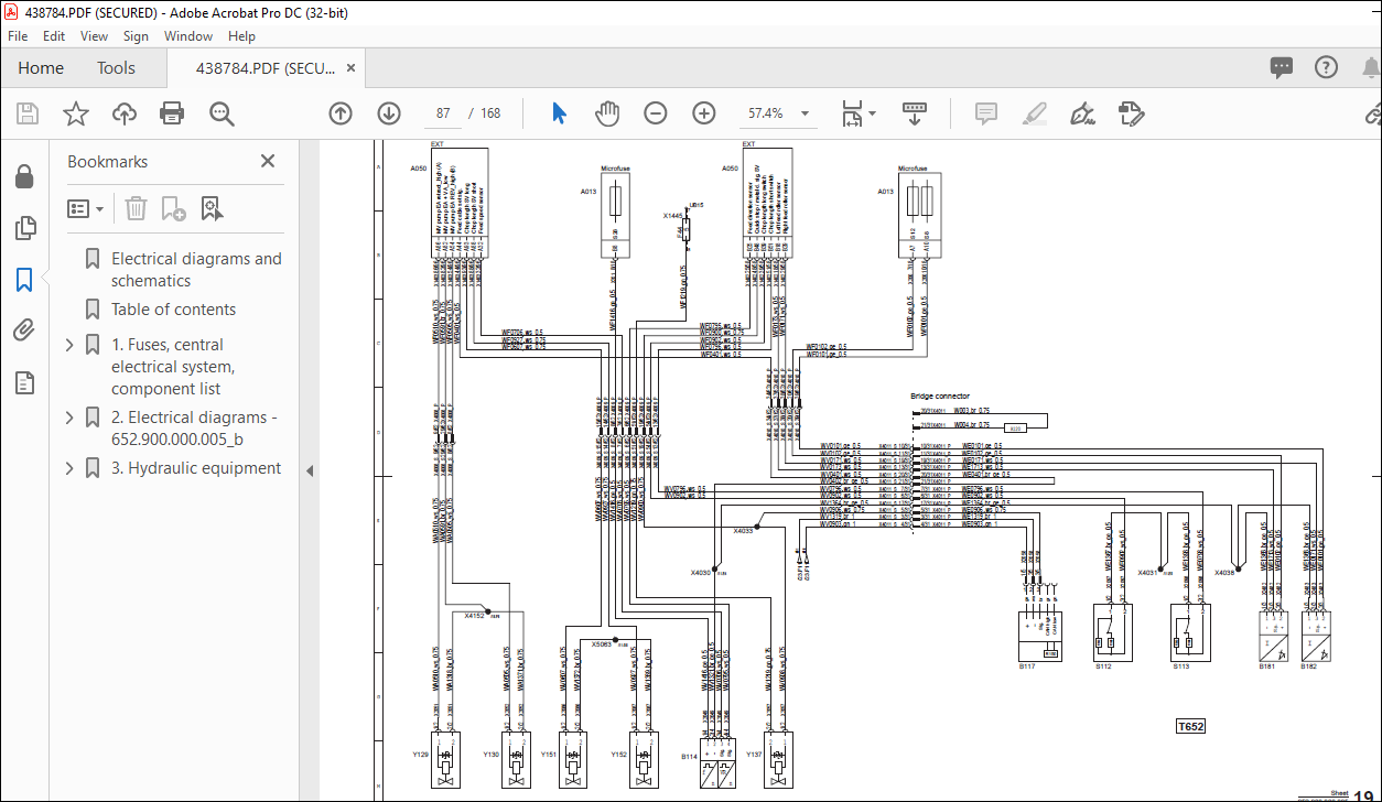
219 Feeding — Sheet 19 2-38
220 Grinding device and shear bar adjustment — Sheet 20 2-40
221 Main transmission and chopper drive — Sheet 21 2-42
222 Spout and cracker — Sheet 22 2-44
223 Suspension, steering, hydraulics monitoring and rear hydraulic
connections — Sheet 23 2-46
224 Display units, operator’s seat, steering column switch and reverse
bleeper — Sheet 24 2-48
225 Vehicle licensing regulations — Sheet 25 2-50
226 Vehicle licensing regulations, wide load and rotary beacon — Sheet
26 2-52
227 Wipers and washer system — Sheet 27 2-54
228 Interior lighting and entrance lighting — Sheet 28 2-56
229 Work light — Sheet 29 2-58
230 Mirror and radio — Sheet 30 2-60
231 Power sockets and camera controller — Sheet 31 2-62
232 Air conditioning system — Sheet 32 2-64
233 Central lubrication, silage additive feed — Sheet 33 2-66
Table of contents
Electrical diagrams and schematics
X990005709011
234 VarioGuide — Sheet 34 2-68
235 Engine control — Sheet 35 2-70
236 Headers/Kemper — Sheet 36 2-72
237 Exhaust gas after-treatment — Sheet 37 2-74
238 MTU engine control — Sheet 38 2-76
239 MTU engine control — Sheet 39 2-78
Hydraulic equipment
1 Low-pressure hydraulics — Sheet 1
2 Working hydraulics — Sheet 2
3 PVG 20 valve function assignments — Sheet 3
4 Detailed plan of linkage — Sheet 4
5 Detailed plan of PVG 20 valves 1–4 — Sheet 5
6 Detailed plan of PVG 20 valves 5-8 — Sheet 6
7 Detailed plan of PVG 20 valves 9–10 — Sheet 7
Detailed plan of PVG 20 valve 11 and rear axle suspension — Sheet
Brake/steering working hydraulics — Sheet 9
10Drive diagram — Sheet 10
1Transmission diagram — Sheet 11
1Overview of high pressure — Sheet 1
Detailed high-pressure plan for hydrostatic drive — Sheet 1
Detailed high-pressure plan for header/feed drive — Sheet 1
High-pressure filling plan — Sheet 15
Speeds and chop lengths — Sheet 16
Main transmission — Sheet 17
Kemper rotary crop headers — Sheet 18
Kemper pickup — Sheet 19
IMAGES PREVIEW OF THE MANUAL:


VIDEO PREVIEW OF THE MANUAL:
PLEASE NOTE:
- This is the same manual used by the dealers to diagnose and troubleshoot your vehicle
- You will be directed to the download page as soon as the purchase is completed. The whole payment and downloading process will take anywhere between 2-5 minutes
- Need any other service / repair / parts manual, please feel free to contact [email protected] . We still have 50,000 manuals unlisted
s.m


