

Fendt Tigo 40 MS Tigo 40 MS D Tigo 50 MS Tigo 50 MS D Tigo 60 MS Tigo 70 MS Operator’s Manual – PDF
DESCRIPTION:
Fendt Tigo 40 MS Tigo 40 MS D Tigo 50 MS Tigo 50 MS D Tigo 60 MS Tigo 70 MS Operator’s Manual – PDF
1.2 Safety Instructions
- YOU are responsible for the SAFE operation and maintenance of your machine.
- YOU must make sure that each person who operates or does work on the machine understands all the SAFETY data in this manual.
- YOU are the key to safety. Good safety procedures prevent accidents to you and each person near you. Make these procedures a set part of your safety sequence.
- Make sure that EVERYONE who operates, does maintenance or works near to the machine obeys the safety precautions.
Follow the safety sequence to prevent the risk of injury or death:
- Owners must complete training with all operators before they operate the machine. This training must be done a minimum of each year
- The operator must read, understand and obey all safety and operation instructions in the manual
- A person who did not read and understand all safety and operation instructions must not operate the machine
- Do not change the equipment. Adjustments not approved by the manufacturer can change the function of the machine and cause damage or personal injury
- Only use approved replacement parts and make sure that only approved technicians do the repair procedures.
1.2.1 General Safety
- Read and understand the manual and all safety decals, before you operate the machine
- Follow all safety regulations, in this manual and instructions or warnings shown on the machine
- Only use the machine for its correct operation
- Only approved persons that understand the operator manual, can operate, drive and do maintenance on the machine
- Keep persons and objects away from parts that move
- Make sure that the installation of all the safety guards and protection devices is correct and they operate correctly
- Always use a tractor with a cabin. Make sure that you close the cabin of the tractor during operation to decrease the quantity of sound. High quantity of sound can cause reduction in hearing
- Put on the correct protective clothing and equipment (gloves, safety glasses and ear protectors)
- Look for hazards and signs of defects (leakage and noise)
- Keep the safety decals clean to make sure that you can see them at all times. Replace safety decals that are missing or you cannot see
- Know the telephone number for emergency medical help in your area
- Speak to your local dealer, if you are not sure of one or more items
- Only connect the machine to the tractor using the procedures in this manual. Only connect the machine to a tractor trailer hitch with your local regulations approval
- Follow the safety instructions on the PTO shaft.
- Make sure that the front axle weight of the tractor is sufficient. Make sure that you do not have more weight than the maximum permitted on the rear axle
- Do not connect the machine to the tractor when the tractor engine is in operation
- Release the pressure from the hydraulic system before you connect or disconnect the hydraulic hoses. Refer to the manual of the tractor
- If the machine has a pneumatic or hydraulic brake, connect the brake hose(s) to the tractor
- Make sure that all safety guards and protection devices are in position
- The PTO shaft must not be used with a missing or damaged guard. You must always use the correct restraining system
- Only used manufacturer approved replacement parts when you replace any part of the PTO shaft
- Do not stand on the PTO or the PTO drive shaft
- Always attach the restraining chain to the PTO
- Do not remove a blockage by hand or by foot. Always use an applicable tool
- Make sure that you set the pressure of the tyres of the transport wheels to the pressure specified. Do not put less than or more than the specified pressures in the tyres
- We recommend to only replace the first tyres with tyres that have speed category and load specifications the same or better than the values in the tyre pressure table. If you do not do this, it can cause dangerous problems.
TABLE OF CONTENTS:
Fendt Tigo 40 MS Tigo 40 MS D Tigo 50 MS Tigo 50 MS D Tigo 60 MS Tigo 70 MS Operator’s Manual – PDF
1 Safety 9
11 Safety Icons 11
12 Safety Instructions 12
121 General Safety 12
122 Safe Driving 13
123 Public Road Transport Safety 13
124 Safe Operation 14
125 Safe Maintenance 14
126 Fire Prevention 14
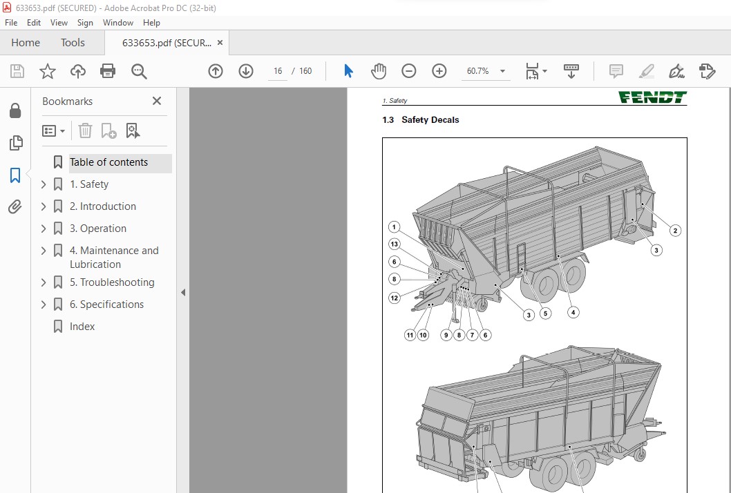
13 Safety Decals 16
14 Danger Zones 20
2 Introduction 21
21 Preface 23
211 Manual Contents 23
212 Vehicle Identification Number (VIN) and VIN Plate 23
22 Intended Use 25
221 Known Misuse 25
23 Description 26
231 Overview 26
232 Drawbar 27
233 Device to stop use without approval 28
234 Pick-up Unit 28
235 Cutting Unit 29
236 Main Drive 31
237 Hydraulic System 32
238 Body 33
239 Floor Conveyor 34
2310 Auto Fill and Release 35
2311 Sensors 35
2312 Discharge Unit (optional) 37
2313 Side Delivery Conveyor (optional) 38
2314 Chassis 39
2315 Trailed Steering and Automatic Steering Axle Lock Function 39
2316 Hydraulic brake away system – optional 39
2317 Dual line hydraulic brake system – optional 40
2318 Other options 40
24 Controllers 42
25 Control Elements on the Control Panel 43
251 Control Elements On the Control Panel 43
26 Control Elements on the ISOBUS Control Panel 46
261 Group 1: Power Supply Button (On or Off) and Indicator LEDs 46
262 Group 2: Fill a Load Functions 47
263 Group 3: Applications and Settings 48
264 Group 4: Load Release Functions 48
265 Group 5: Counter Functions 49
27 Control Elements of the ISOBUS Terminal 51
271 Main Menu 51
272 Control Elements on the ISOBUS Terminal 51
273 General Settings Menu 52
Table of contents
LM07149254
274 Fill a Load Menu 53
275 Release a Load Menu 54
276 Counter Menu 56
277 Maintenance Menu 57
28 Control Elements on the Machine 59
281 Control Buttons on the Machine 59
3 Operation 61
31 First Use 63
311 Prepare for the First Use 63
312 Assembly by the Dealer 63
313 Adjust the Automatic Load-Sensitive Brake System (pneumatic brakes) 63
314 Adjust the Load Sensing System 63
315 Adjust the height of the hydraulic drawbar 64
316 Install the Power Take-Off (PTO) Overload Protection 65
317 Adjust the Length of the Power Take-Off (PTO) Shaft 66
318 Connect a Preservative Application System (optional) 68
32 Connect the Machine to the Tractor 69
321 Side Door Open 69
322 Side Door Close 70
323 Connect the Lighting Cable 71
324 Connect the User Interface(s) 71
325 Connect to the Control Panel 72
326 Connect an ISOBUS control panel (tractor with ISOBUS and LBS ISOBUS socket 72
327 Connect an ISOBUS control Panel (tractor without ISOBUS) 72
328 Connect the ABS plug – dual line brakes only 73
329 Connect the hydraulic and pneumatic hoses – single line brake system 73
3210 Connect the hydraulic hoses – dual line brake system 74
3211 Connect the Drawbar Coupler 76
3212 Connect the Hydraulic Break-Away System (optional) 77
3213 Connect the Power Take-Off (PTO) Shaft 77
33 Transport and Drive Position 79
331 Put the Park Jack in the Drive Position with the Manual Drawbar 80
332 Put the Park Jack in the Drive Position with the Hydraulic Drawbar 80
333 Drain the Air Container of the Pneumatic Brake System (optional) 81
34 Prepare the Machine for a Load 83
341 Move the Side Delivery Conveyor (optional) to the Storage Position 83
342 Adjust the Work Height of the Pick-up 85
343 Adjust the Height of the Wind Guard 85
344 Adjust the Distance Between the Knives and the Rotor 86
345 Adjust the Length of the Turn Buckle Fork Axles 87
346 Select the Number of Knives 87
347 Move the lower knives group in or out 88
348 Move the sub group of the upper knives group in or out 88
349 Move the full knives assembly in or out Hydraulically (work/service position) 89
3410 Move the whole knives assembly in or out Manually (work/service position) 89
35 Fill the machine 91
351 Fill the Machine Automatically 91
352 Fill the Machine Manually 92
36 Empty the Machine 94
361 Empty the machine automatically with the ISOBUS terminal 94
362 Empty the machine manually with the ISOBUS terminal 95
363 Empty the machine manually with the ISOBUS control panel Tigo 96
37 Disconnect the machine from the tractor 98
371 Put the Park Jack in the Park Position 99
372 Engage the Park Brake and Put the Wheel Chocks Against a Wheel 101
Table of contents
LM07149254
4 Maintenance and Lubrication 103
41 Maintenance After the First Operation 105
42 Maintenance Schedule 106
43 Other Maintenance 109
44 Maintenance Before and After Storage 110
45 Maintenance Procedures 112
451 Clean the Machine 112
452 Replace a Fuse 112
453 Replace the Hydraulic Filter 113
46 Maintenance on the Power Take-Off Shaft and the Main Drive 114
461 Apply Grease to the Power Take-Off (PTO) Shaft 114
462 Apply Grease to the Main Shaft Clutch 115
463 Replace the Oil of the Main Shaft Gearbox 115
47 Maintenance on the Drawbar 116
471 Apply Grease to the Drawbar Coupler 116
48 Maintenance on the Pick-up Unit 117
481 Lubricate the Drive Chains of the Pick-up Unit 117
482 Tighten the Drive Chains of the Pick-up Unit 117
483 Apply Grease to the Bearing of the Pick-up Drive Sprocket 117
484 Apply Grease to the Freewheel Clutch of the Pick-up Unit 118
485 Apply Grease to the Pivots of the Pick-up Guide Wheels 119
49 Maintenance on the Cutting Unit 120
491 Sharpen the Knives or Replace the Knives 120
492 Prepare the Cutting Unit for Maintenance on the Knives 120
493 Make the Knives Accessible for Maintenance 120
494 Remove a Knife 122
495 Install a Knife After Removal 123
496 Move the Knife Assembly Back to the Work Position 123
497 Apply Grease to the Rake Feeder 126
410 Maintenance on the Floor Conveyor 128
4101 Adjust the Tension in the Chains of the Floor Conveyor 128
4102 Apply Grease to the Drive Shaft Bearings of the Floor Conveyor 128
4103 Lubricate the Running Wheels of the Floor Conveyor 128
4104 Replace the Gearbox Oil of the Floor Conveyor 129
411 Maintenance on the Discharge Unit (optional) 130
4111 Adjust the Tension and Lubricate the Drive Chains of the Discharge Unit 130
4112 Apply Grease to the Drive Shaft of the Discharge Unit 130
4113 Replace the Oil of the Rear Gearbox of the Discharge Unit 131
4114 Replace the Oil of the Front Gearbox of the Discharge Unit 132
412 Maintenance on the Side Delivery Conveyor 133
413 Maintenance on the Chassis 134
4131 Tighten the Transport Wheel Nuts 134
4132 Replace the Transport Wheel 134
4133 Apply Grease to the Bearings of the Steering Spindles 135
4134 Lubricate the Leaf Spring Equalizer Bearings, Pivot Points and Slide Points 136
4135 Apply Grease to the Locking Cylinder of the Trailed Steering 136
4136 Apply Grease to the Brake Camshafts 137
4137 Apply Grease to the Slack Adjuster 137
4138 Measure the Thickness of the Brake Linings 138
4139 Examine the Slack Adjuster 138
41310 Adjust the Slack Adjuster 138
41311 Measure the Clearance of the Wheel Hub Bearing 139
41312 Examine the Steering Axle 139
41313 Examine the Axle Suspension 140
Table of contents
LM07149254
41314 Clean the Filters of the Pneumatic Brake System (if present) 141
5 Troubleshooting 143
51 Problems and Suggested Solutions 145
52 Error Codes 147
6 Specifications 151
61 Specifications 153
611 Table of Standard Wheel Nut Torques 154
612 Table of Standard Tire Pressures 154
62 Disposal 155
7 Index 157
Table of contents
LM07149254
VIDEO PREVIEW OF THE MANUAL:

IMAGES PREVIEW OF THE MANUAL:
PLEASE NOTE:
- This is the same manual used by the DEALERSHIPS to SERVICE your vehicle.
- The manual can be all yours – Once payment is complete, you will be taken to the download page from where you can download the manual. All in 2-5 minutes time!!
- Need any other service / repair / parts manual, please feel free to contact us at heydownloadss @gmail.com . We may surprise you with a nice offer
S.M


