Zoomlion Truck Crane QY30VL Spare Parts Catalog Manual – PDF DOWNLOAD
$28.95
Zoomlion Truck Crane QY30VL Spare Parts Catalog Manual – PDF DOWNLOAD
Description
Zoomlion Truck Crane QY30VL Spare Parts Catalog Manual – PDF DOWNLOAD
FILE DETAILS:
Zoomlion Truck Crane QY30VL Spare Parts Catalog Manual – PDF DOWNLOAD
Language : English
Pages : 336
Downloadable : Yes
File Type : PDF
IMAGES PREVIEW OF THE MANUAL:
DESCRIPTION:
Zoomlion Truck Crane QY30VL Spare Parts Catalog Manual – PDF DOWNLOAD
Foreword:
- ZOOMLION truck crane is a product integrating our many years’ experience and
advanced technologies. - This catalog introduces the structure and assembling features of
spare parts as well as the purchased spare parts required in the main systems. - Carefully reading this spare parts catalog will save your time during repair and order..
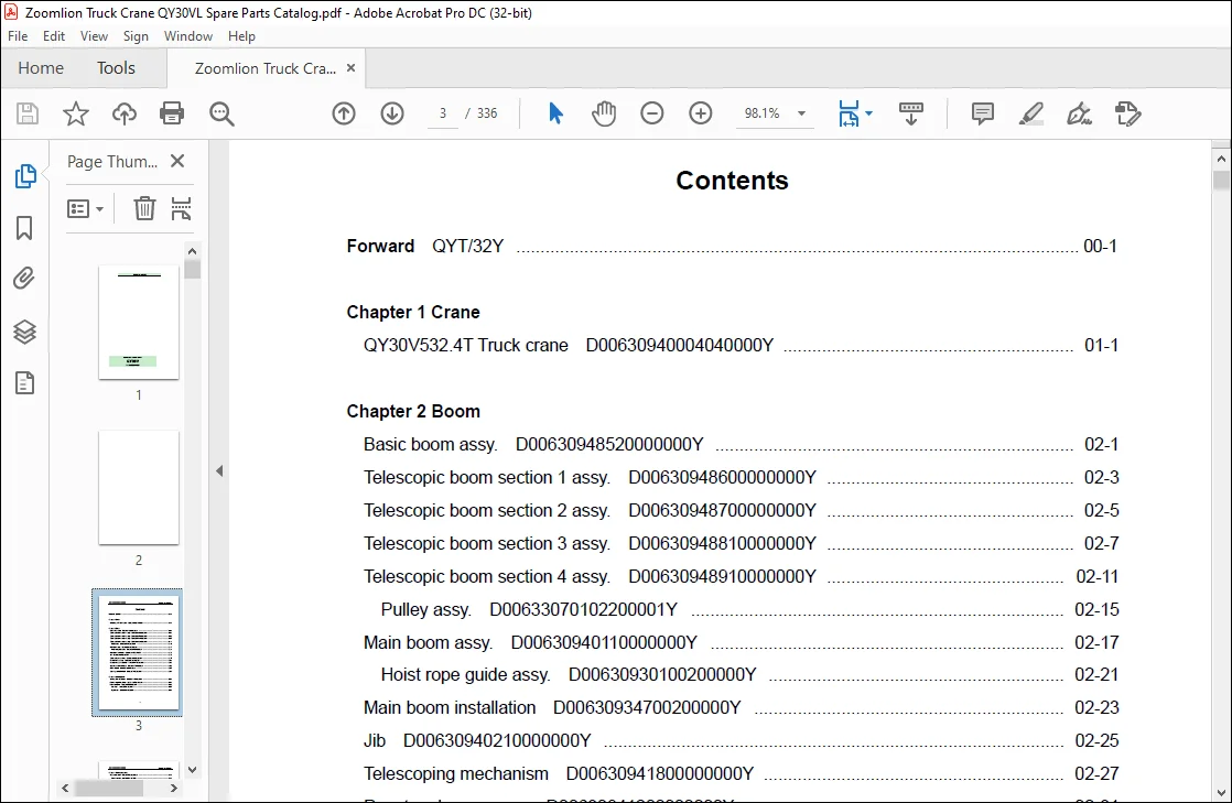
TABLE OF CONTENTS:
Zoomlion Truck Crane QY30VL Spare Parts Catalog Manual – PDF DOWNLOAD
Forward QYT/32Y 00-1
Chapter 1 Crane
QY30V532 4T Truck crane D00630940004040000Y 01-1
Chapter 2 Boom
Basic boom assy D00630948520000000Y 02-1
Telescopic boom section 1 assy D00630948600000000Y 02-3
Telescopic boom section 2 assy D00630948700000000Y 02-5
Telescopic boom section 3 assy D00630948810000000Y 02-7
Telescopic boom section 4 assy D00630948910000000Y 02-11
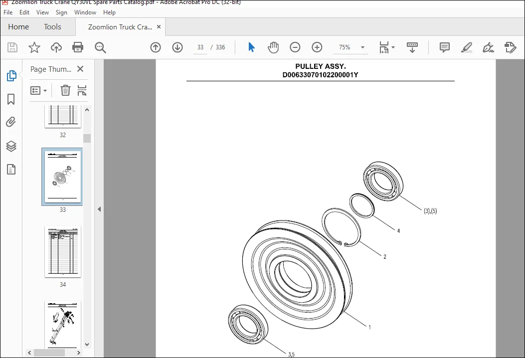
Pulley assy D00633070102200001Y 02-15
Main boom assy D00630940110000000Y 02-17
Hoist rope guide assy D00630930100200000Y 02-21
Main boom installation D00630934700200000Y 02-23
Jib D00630940210000000Y 02-25
Telescoping mechanism D00630941800000000Y 02-27
Rooster sheave assy D00630841200000000Y 02-31
Rooster sheave installation D00630944720600000Y 02-33
Angle indicator installation D00630947100000000Y 02-35
Boom support D00630940330000000Y 02-37
Securing device for hook D00630874300000000Y 02-39
Chapter 3 Slewing table
Slewing table installation D00630944720800000Y 03-1
Counterweight installation D00631254720400000Y 03-3
Hood installation D00630870500000001Y 03-5
Left hood 1991900070-102388Y 03-7
Right hood 1991900116-102388Y 03-9
QY30V532 4T/ M32Y
II
Chapter 4 Hoist mechanism
Hoist mechanism D00630873500000000Y 04-1
Winch reducer 1030200079-102377Y 04-3
Winch reducer 1030200079-100012Y 04-5
Winch reducer 1030200079-100015Y 04-9
Winch motor 1010100011-100025Y 04-11
Main hook 1090400112-100017Y 04-15
Main hook 1090400112-100018Y 04-17
Main hook 1090400112-100019Y 04-19
Auxiliary hook 1090400080-100018Y 04-21
Chapter 5 Slewing mechanism
Slewing mechanism D00630844400000000Y 05-1
Slewing reducer 1030200039-100012Y 05-3
Slewing reducer 1030200039-100013Y 05-7
Slewing motor (plunger type) 1010100006Y 05-9
Slewing ring and its installation D00630914510000000Y 05-11
Chapter 6 Operator’s cab
Operator’s cab assy 1130000182-100037Y 06-1
Instrument console 1130000182-100037Y 06-3
Window glass and door assy 1130000182-100037Y 06-5
Boarding 1130000182-100037Y 06-7
Wiper and handrail 1130000182-100037Y 06-9
Seat installation 1130000182-100037Y 06-11
Guard rail installation 1130000182-100037Y 06-13
Operator’s cab installation D00631254720800000Y 06-15
Engine control pedal installation D00631124010400000Y 06-17
Chapter 7 Outrigger
Outrigger operating mechanism D00630875800000000Y 07-1
Outrigger and its cylinder installation D00630874700400000Y 07-3
The 5th outrigger D00630871100000000Y 07-5
Outrigger D00633101100200000Y 07-7
Support pad D00630871300000000Y 07-9
QY30V532 4T/ M32Y
III
Chapter 8 Air conditioning system for vehicle
Air adjusting device D00630877600000000Y 08-1
A/C bracket and its installation D00631147600400000Y 08-3
A/C assy D00630877600400000Y 08-5
Condenser assy 1130100056-100026Y 08-7
Liquid heater installation D00630877620200000Y 08-9
Water tank installation of heater D00631257500600000Y 08-11
Main machine installation of liquid heater D00630877620210000Y 08-13
Liquid heater assy 1130100090-102208Y 08-15
Oil tank installation of heater D00631147500400000Y 08-17
Chapter 9 Electrical system
Electrical system – operator’s cab D00630946280000000Y 09-1
Instrument panel assy D00630946280200000Y 09-5
Rocker switch assy D00630946280210000Y 09-7
Mounting plate assy of instrument console D00630946280400000Y 09-9
Deadman switch 1031700077-102340Y 09-11
Electrical system – slewing table D00630946390000000Y 09-13
Electrical system – main boom D00630946490000000Y 09-15
Electrical system – jib D00630946520000000Y 09-17
Load moment limiter 1021500404-102316Y 09-19
Length/angle sensor LWG208-O 09-21
CAN terminal box assy -A 1021500404-102316-02 09-23
Chapter 10 Hydraulic system
Schematic diagram – hydraulic system D00630941560000000Y 10-1
Brake valve – slewing mechanism 1010300496-006500Y 10-3
Brake valve – slewing mechanism installation D00630874880400000Y 10-5
Cushion valve – slewing mechanism 1010300495-006500Y 10-7
Pilot-operated directional control valve XCHY-F15L-2 10-9
Damping check valve XCHY-F15L-A-2-1 10-11
Relief valve CB-F15L-4 10-13
Cushion control valve XCHY-F15L-1 10-15
Cushion valve – slewing mechanism installation D00630874800200000Y 10-17
Electro-hydraulic directional control valve 1010302101-006500Y 10-19
QY30V532 4T/ M32Y
IV
Base plate assembly YYKY-H25L-1 10-21
Makeup valve YYKY-H25L-1-2 10-23
Back pressure valve YYKY-H25L-1-3 10-25
Balance valve 1010300194-006500Y 10-27
Balance valve – hoist mechanism 1010300475-006500Y 10-29
Shuttle valve XCYFS-G25L-4T-3-3 10-31
Brake valve (controlling 2 winches) 1010300473-006500Y 10-33
Brake valve (controlling 2 winches) 1010300473-100031Y 10-35
Superstructure operating valve 1010302563-006500Y 10-37
Oil inlet/return valveⅠ ZYYFS-G25L-4T-4 10-39
Flow stabilizator XCYFS-G25L-4T-1-2 10-41
Throttle check valve FS-G28L-4T-1-2 10-43
Telescopic valve ZYYFS-G25L-4T-1 10-45
Overload valve ZYYFS-G25L-4T-1-1 10-47
Overload valve assembly QYY-F20L-4T-9-1 10-49
Derricking valve ZYYFS-G25L-4T-A-2 10-51
Hoist valve ZYYFS-G25L-4T-3 10-53
Superstructure operating valve installation D00630874800800000Y 10-55
Multiple unit valve 1010300042-006500Y 10-57
Relief valve QYZ15/10-01-2 10-59
Check valve XCDL15/10-5W-3A 10-61
Overload valve XCDL15/10-5W-2 10-63
Manual unloading valve 1010300000-006500Y 10-65
Manual unloading valve 1010300000-100031Y 10-67
Combination control valveⅠ 1010301821-006500Y 10-69
Check valve ZYKY-C6L-E-I-2 10-71
Fluid filling valve ZHKY-C6E-4 10-73
Relief valve ZHKY-C6E-2 10-75
Connecting block of accumulator ZYKY-C6L-E-I-3 10-77
Combination control valve I installation D00630874880600000Y 10-79
Combination control valve II 1010301822-006500Y 10-81
Combination control valve II installation D00630874880800000Y 10-83
Pipe layout drawing – hydraulic system, superstructure D00630942500200000Y 10-85
Pipe layout drawing – control module D00630942500400000Y 10-89
Pipe layout drawing – hydraulic system, chassis D00630941750000000Y 10-91
QY30V532 4T/ M32Y
V
Hydraulic tank D00630873000000000Y 10-94
Air filter 1010500000-101281Y 10-96
Return filter 1010600009-101281Y 10-98
Return filter 1010600009-101375Y 10-100
Hydraulic oil tank installation D00630874800600000Y 10-102
Oil pump drive device D00630873900000000Y 10-104
Quadruple gear pump 1010000281-100013Y 10-106
Quadruple gear pump 1010000135-100032Y 10-110
Oil cooling device D00630947420000000Y 10-112
Air-cooled unit 1010400002-100026Y 10-114
Two-way hydraulic lock installation D00631124800200000Y 10-116
Two-way hydraulic lock 1010300282-006500Y 10-118
Two-way hydraulic lock 1010300282-100029Y 10-120
Derricking cylinder 1010200365-006400Y 10-122
Derricking cylinder installation D00630844820600000Y 10-124
Telescopic cylinder I D00630841910000000Y 10-126
Telescopic cylinder II 0630845300000000Y 10-128
Balance valve 1010300314-100031Y 10-130
Horizontal cylinder 1010200042-006400Y 10-132
Front vertical cylinder D00630932200200001Y 10-134
Rear vertical cylinder D00630932200400001Y 10-136
The 5th outrigger D00630921100400000Y 10-138
Two-way hydraulic lock 1010300275-006400Y 10-140
Centre revolving joint 1011200016-100029Y 10-142
Centre revolving joint installation D00630874880200000Y 10-144
Questions? Email us: [email protected]
PLEASE NOTE:
- This is the SAME exact manual used by your dealers to fix your vehicle.
- The same can be yours in the next 2-3 mins as you will be directed to the download page immediately after paying for the manual.
- Any queries / doubts regarding your purchase, please feel free to contact [email protected]
S.V