YANMAR 6LY3-ETP 6LY3-STP 6LY3-UTP MARINE DIESEL ENGINE SERVICE MANUAL 0BLY3-G00100 – PDF DOWNLOAD
Original price was: $85.95.$28.95Current price is: $28.95.
YANMAR 6LY3-ETP 6LY3-STP 6LY3-UTP MARINE DIESEL ENGINE SERVICE MANUAL 0BLY3-G00100 – PDF DOWNLOAD
Description
YANMAR 6LY3-ETP 6LY3-STP 6LY3-UTP MARINE DIESEL ENGINE SERVICE MANUAL 0BLY3-G00100 – PDF DOWNLOAD
IMAGES PREVIEW OF THE MANUAL:
DESCRIPTION:
YANMAR 6LY3-ETP 6LY3-STP 6LY3-UTP MARINE DIESEL ENGINE SERVICE MANUAL 0BLY3-G00100 – PDF DOWNLOAD
FOREWORD:
This service manual has been compiled for engineers engaged in sales, service, inspection and
maintenance. Accordingly, descriptions of the construction and functions of the engine are emphasized
in this manual, while items, which should already be common knowledge, are omitted.
One characteristic of a marine diesel engine is that its performance in a vessel is governed by the
applicability of the vessel’s hull construction and its steering system.
TABLE OF CONTENTS:
YANMAR 6LY3-ETP 6LY3-STP 6LY3-UTP MARINE DIESEL ENGINE SERVICE MANUAL 0BLY3-G00100 – PDF DOWNLOAD
1 General 1
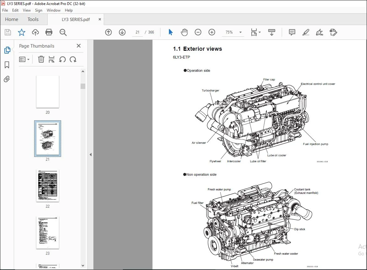
1 1 Exterior views 1
1 2 Main specifications 2
1 3 Fuel oil, lubricating oil and cooling water 3
1 3 1 Fuel oil 3
1 3 2 Lubricating oil 5
1 3 3 Cooling water 7
1 4 Engine outline 8
1 5 Piping diagrams 10
1 6 Exhaust gas emission regulation 11
1 6 1 Engine identification 11
1 6 2 EPA exhaust gas emission standard 12
1 6 3 EPA guarantee conditions for emission standard 13
2 Inspection and adjustment 14
2 1 Periodic maintenance schedule 14
2 2 Periodic inspection and maintenance procedure 16
2 2 1 Check before starting 16
2 2 2 Inspection after initial 50 hours or one month operation 20
2 2 3 Inspection every 50 hours or monthly 22
2 2 4 Inspection on initial 250 hours or one year 27
2 2 5 Inspection every 250 hours or one year 33
2 2 6 Inspection every year 39
2 2 7 Inspection every 500 hours or two years 41
2 2 8 Inspection 2,000 hours or every two years 42
2 2 9 Inspection every 1,000 hours or four years 43
2 2 10 Inspection every 2000 hours or eight years 45
2 3 Adjusting the no-load minimum speed 49
2 4 Thermostat inspection 50
2 5 Test running 51
2 5 1 Preliminary precautions 51
2 5 2 Test running procedure 51
2 5 3 Check points and precautions during running 52
2 6 Long storage 53
3 Troubleshooting 54
3 1 Preparation before troubleshooting 54
3 2 Troubleshooting 55-1
3 2 1 Troubleshooting from trouble symptom 55-1
3 2 2 Troubleshooting of fuse 56
3 3 Trouble code 64-1
3 3 1 List of DTC (Diagnostic Trouble Code) 64-1
3 3 2 Temperature / Pressure Sensor Diagnosis 64-37
3 3 3 Other Wiring Diagram 64-43
3 3 4 TELEFLEX i5501E Display “Alarm Screen Information” 64-49
3 3 5 ECU Connector Pin Configuration 64-49
3 3 6 Abbreviation 49
4 Disassembly and reassembly 65
4 1 Disassembly and reassembly precautions 65
4 2 Disassembly and reassembly tools 66
4 2 1 General hand tools 66
4 2 2 Special hand tools 68
4 2 3 Measuring instruments 71
4 2 4 Other material 75
4 3 Disassembly and reassembly 77
4 3 1 Disassembly 77
4 3 2 Reassembly 83
5 Inspection and servicing of basic engine parts 103
5 1 Cylinder block 103
5 1 1 Inspection of parts 103
5 1 2 Cleaning of oil holes 103
5 1 3 Color check procedure 104
5 1 4 Replacement of plugs 105
5 1 5 Cylinder bore measurement 106
5 2 Cylinder head 107
5 2 1 Inspecting the cylinder head 108
5 2 2 Valve seat correction procedure 109
5 2 3 Intake / exhaust valves, valve guides 111
5 2 4 Valve springs 114
5 2 5 Nozzle sleeve 116
5 2 6 Assembling the cylinder head 117
5 2 7 Measuring top clearance 118
5 2 8 Intake and exhaust rocker arms 119
5 2 9 Adjustment of valve clearance 120
5 3 Piston and piston pins 121
5 3 1 Piston 121
5 3 2 Piston pin 123
5 3 3 Piston rings 124
5 4 Connecting rod 127
5 4 1 Inspecting the connection rod 127
5 4 2 Crank pin metal 129
5 4 3 Piston pin bushing 131
5 4 4 Assembling piston and connecting rod 132
5 5 Crankshaft and main bearing 133
5 5 1 Crankshaft 133
5 5 2 Main bearing 135
5 6 Camshaft and Tappets 136
5 6 1 Camshaft 136
5 6 2 Tappets 138
5 7 Timing gear 140
5 7 1 Inspecting the gears 140
5 7 2 Gear timing marks 141
5 8 Flywheel and housing 142
5 8 1 Specifications of flywheel 142
5 8 2 Ring gear 143
5 8 3 Position of top dead center 143
6 Fuel injection equipment 144
6 1 Fuel Injection pump / governor / timer 144
6 1 1 Fuel system diagram 144
6 1 2 Fuel injection pump specifications 145-1
6 1 3 Governor structure and function 145-3
6 1 4 Timer structure and function 145-4
6 1 5 Removing a fuel injection pump assembly 146
6 1 6 Installing a fuel injection pump assembly 149
6 1 7 Troubleshooting of fuel injection pump 157
6 2 Fuel Injection nozzle 159
6 2 1 Functioning of fuel injection nozzle 159
6 3 Fuel feed pump 161
6 3 1 Fuel feed pump specifications 162
6 3 2 Fuel feed pump disassembly 162
6 3 3 Fuel feed pump inspection 163
6 3 4 Fuel feed pump reassembly 163
6 3 5 Fuel feed pump adjustment 164
6 4 Fuel filter 166
6 4 1 Fuel filter specifications 166
6 4 2 Fuel filter inspection 167
6 5 Electronic Control System 167-2
7 Intake and exhaust system 168
7 1 Intake system 168
7 2 Exhaust system 168
7 2 1 Mixing elbow inspection 168
8 Lubrication system 169
8 1 Lubrication system 169
8 2 Lube oil pump 170
8 2 1 Lube oil pump construction 170
8 2 2 Specifications of lube oil pump 171
8 2 3 Lube oil pump disassembly and reassembly 172
8 2 4 Oil pressure control valve construction 174
8 3 Lube oil filter 175
8 3 1 Lube oil filter construction 175
8 3 2 Lube oil filter replacement 175
8 4 Lube oil cooler 176
8 4 1 Lube oil cooler construction 176
8 4 2 Inspecting the lube oil cooler 176
8 5 Rotary waste oil pump (Optional) 177
9 Cooling water system 178
9 1 Cooling water system 178
9 2 Seawater pump 179
9 2 1 Specifications of seawater pump 179
9 2 2 Seawater pump disassembly 180
9 2 3 Seawater pump Inspection 180
9 2 4 Seawater pump reassembly 181
9 3 Fresh water pump 182
9 3 1 Fresh water pump construction 182
9 3 2 Specifications of fresh water pump 183
9 3 3 Fresh water pump disassembly 183
9 3 4 Fresh water pump inspection 184
9 4 Heat exchanger 186
9 4 1 Heat exchanger construction 186
9 4 2 Specifications of heat exchanger 186
9 4 3 Disassembly and reassembly 186
9 4 4 Heat exchanger inspection 187
9 5 Pressure cap and coolant recovery tank 188
9 5 1 Pressure cap construction 188
9 5 2 Pressure cap pressure control 188
9 5 3 Pressure cap inspection 189
9 5 4 Function of the coolant recovery tank 189
9 5 5 Specifications of coolant recovery tank 189
9 5 6 Mounting the coolant recovery tank 190
9 5 7 Precautions on usage of the coolant recovery tank 190
9 6 Thermostat 191
9 6 1 Functioning of thermostat 191
9 6 2 Thermostat construction 191
9 6 3 Characteristics of thermostat 192
9 6 4 Thermostat inspection 192
9 6 5 Testing the thermostat 192
9 7 Seacock (Optional) 193
9 8 Bilge pump and bilge strainer (Optional) 194
9 8 1 Introduction 194
9 8 2 Description 195
9 8 3 Cautions 196
9 8 4 Assembly procedure 198
9 8 5 Cautions for Assembling 200
9 8 6 Troubleshooting 202
10 Turbocharger 203
10 1 Construction and function 204
10 1 1 Outline 204
10 2 Standards for maintenance and check 206
10 2 1 Standards for maintenance and check 206
10 2 2 Tightening torque 207
10 3 Periodical checking procedure 208
10 3 1 Periodical checking interval 208
10 3 2 Checking procedure 208
10 4 Disassembly procedure 210
10 4 1 Preparations for disassembly 210
10 4 2 Check before disassembly 212
10 4 3 Disassembly 213
10 5 Cleaning and checking procedure 215
10 5 1 Cleaning 215
10 5 2 Checking procedure 217
10 6 Reassembling procedure 220
10 6 1 Preparations for reassembly 220
10 6 2 Reassembling procedure 220
10 7 Handling after reassembly 223
10 7 1 Precautions for mounting the turbocharger to the engine 223
10 8 Troubleshooting 224
10 8 1 Exhaust gas is dense 224
10 8 2 Whitish exhaust gas 224
10 8 3 Too early oil shortage 225
10 8 4 Output drop 225
10 8 5 Poor follow-up of supercharger 225
10 8 6 Unusual sound or vibration 225
11 Reduction and reversing gear 226
12 Remote control 227
12 1 Electronic control system (ECS) 227
12 1 1 Digital display 228
12 1 2 Rocker switch panel 230
12 1 3 Control head (Shift &Throttle) 231
13 Electrical system 232
13 1 Electrical system 232
13 1 1 Wiring diagram 232
13 2 Battery 233
13 2 1 Construction 233
13 2 2 Battery capacity and battery cables 234
13 2 3 Inspection 235
13 2 4 Charging 237
13 2 5 Battery storage precautions 238
13 3 Starting Motor 239
13 3 1 Specifications 239
13 3 2 Characteristics 239
13 3 3 Structure 240
13 3 4 Wiring diameter of a starting motor 242
13 4 Alternator standard, 12V/80A 243
13 4 1 Specifications 243
13 4 2 Structure 244
13 4 3 Wiring diagram 245
13 4 4 Standard output characteristics 246
13 4 5 Inspection 247
13 5 Warning devices 248
13 5 1 Sensor installation position 248
13 5 2 Lube oil pressure sensor and boost sensor 250
13 5 3 Temperature sensor for water, lube oil and fuel 251
13 6 Air heater 251-2
13 7 Fuse, relay and harness 251-3
14 Service standards 252
14 1 Engine tuning 252
14 2 Engine body 253
14 2 1 Cylinder head 253
14 2 2 Camshaft and gear train 254
14 2 3 Cylinder block 255
15 Tightening torque for bolts and nuts 258
15 1 Main bolt and nut 258
15 2 Standard bolts and nuts (without lube oil) 259
Customer Support: [email protected]
https://vimeo.com/739540824
PLEASE NOTE:
- This is the same manual used by the dealers to diagnose and troubleshoot your vehicle
- You will be directed to the download page as soon as the purchase is completed. The whole payment and downloading process will take anywhere between 2-5 minutes
- Need any other service / repair / parts manual, please feel free to contact [email protected] . We still have 50,000 manuals unlisted
I.G