Yamaha FJR1300(N) 2001 Service Manual 5JW1-AE1 – PDF DOWNLOAD
$19.95
Yamaha FJR1300(N) 2001 Service Manual 5JW1-AE1 – PDF DOWNLOAD
Description
Yamaha FJR1300(N) 2001 Service Manual 5JW1-AE1 – PDF DOWNLOAD
FILE DETAILS:
Yamaha FJR1300(N) 2001 Service Manual 5JW1-AE1 – PDF DOWNLOAD
Language : English
Pages : 617
Downloadable : Yes
File Type : PDF
IMAGES PREVIEW OF THE MANUAL:
TABLE OF CONTENTS:
Yamaha FJR1300(N) 2001 Service Manual 5JW1-AE1 – PDF DOWNLOAD
Cover 1
TABLE OF CONTENTS 7
GENERAL INFORMATION 10
Identification 12
Features 13
FI System 14
Fuel Control Block 15
ECU 16
Fuel pump 18
Pressure Regulator 19
Fuel Injector 20
Crankshaft Position Sensor 21
Cylinder identification sensor 22
Throttle position sensor 23
Intake air pressure sensor and atmospheric pressure sensor 24
Coolant temperature and Intake temperature sensors 25
O2 sensor 26
Lean angle cut-off switch 27
Operation and control 28
Three-way Catalytic Converter System 37
Air Induction System 41
Instrument Panel 43
Important Information 46
Special Tools 49
SPECIFICATIONS 55
General Specifications 57
Engine Specifications 58
Chassis Specifications 67
Electrical Specifications 71
General Tightening Torque Specifications 74
Engine Tightening Torques 75
Tightening Sequences 78
Chassis Tightening Torques 79
Lubrication Points and Lubricant Types 81
Oil Flow Diagrams 84
Cooling System Diagrams 94
Cable Routing 98
PERIODIC CHECKS AND ADJUSTMENTS114
Introduction and Intervals116
Seats and Fuel Tank118
Air Filter Case123
Cowlings and Covers125
Valve clearance130
Synchronizing the throttle bodies136
Exhaust gas at idle138
Exhaust gas volume140
Engine idling speed143
Throttle cable free play145
Spark plugs147
Ignition timing148
Compression pressure150
Engine oil level152
Changing the engine oil154
Measuring the engine oil pressure156
Adjusting and checking the clutch158
Bleeding the clutch system159
Cleaning the air filter element161
Throttle body joints162
Fuel, vacuum and crankcase breather hoses163
Exhaust system164
Coolant level165
Cooling system166
Changing coolant167
Front brake adjustment170
Rear brake adjustment171
Brake fluid level172
Brake pads173
Rear brake light switch173
Brake hoses174
Bleeding the brake system175
Shift pedal adjustment176
Final drive oil177
Steering head178
Front fork180
Rear shock absorber183
Tires184
Wheels186
Chassis lubrication187
Checking and Charging the battery189
Fuses194
Headlight bulbs196
CHASSIS201
Front wheel and brake disks203
Rear wheel and brake disk211
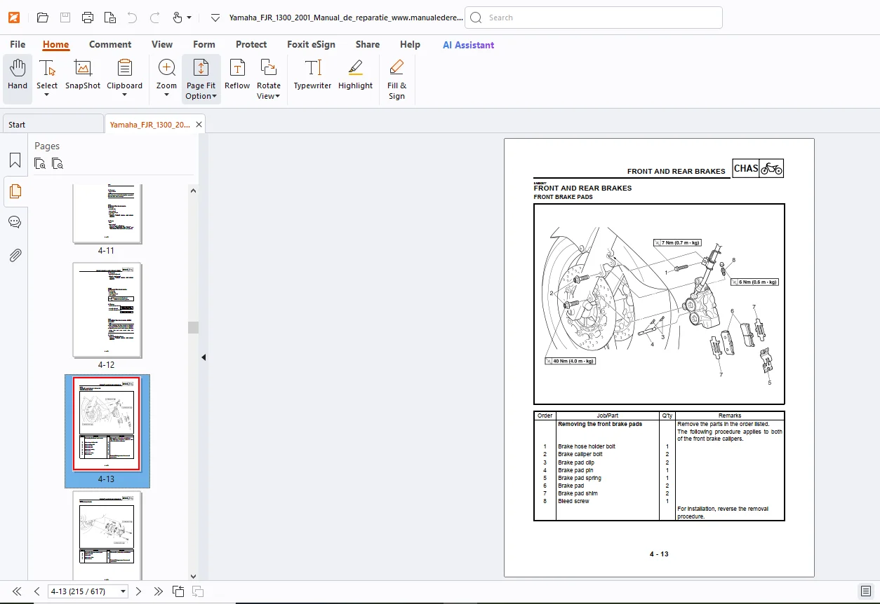
Front and rear brakes215
Front brake pads215
Rear brake pads216
Replacing front pads217
Replacing rear pads219
Front master cylinder222
Rear master cylinder225
Disassembling the master cylinders228
Checking master cylinders229
Assembling and installing the front master cylinder230
Assembling and installing the rear master cylinder232
Front brake calipers235
Rear brake caliper237
Disassembling brake calipers239
Checking the brake calipers241
Assembling and installing the front calipers242
Assembling and installing the rear caliper244
Hydraulic clutch248
Disassembling the master cylinder251
Checking the master cylinder252
Assembling and installing the master cylinder253
Clutch release cylinder256
Disassembling the release cylinder258
Checking and assembling the release cylinder259
Front fork262
Removing and disassembling fork legs265
Checking the fork legs267
Assembling the fork legs268
Installing the fork legs272
Handlebars273
Steering head279
Rear shock absorber and relay arm284
Swingarm289
Shaft drive294
Troubleshooting294
Checking for contamination and leaks297
Ring gear backlash298
Ring gear to stopper bolt clearance300
Removal and disassembly302
Removing and installing ring gear bearings307
Aligning the final drive pinion gear and ring gear309
Reassembling the final drive312
Installing the U-joint and final drive assembly314
ENGINE316
Mufflers and exhaust pipe assembly320
Leads and hoses321
Removing the engine323
Installing the engine325
Camshafts327
Removing330
Checking331
Camshaft sprockets332
Timing chain tensioner333
Installing 333
Cylinder head338
Removing338
Checking339
Installing340
Valves and valve springs343
Removing343
Checking345
Installing351
Generator and starter clutch353
Pickup coil rotor360
Clutch364
Shift shaft374
Oil pan and oil pump378
Middle gear385
Removing385
Disassembling387
Checking and assembly391
Installing the middle drive shaft assembly392
Installing the middle driven shaft assembly393
Measuring and adjusting backlash394
Aligning the middle gear398
Crankcase401
Separating the crankcase401
Disassembling and checking the crankcase405
Assembling the crankcase407
Connecting rods and pistons411
Removing connecting rods and pistons411
Checking the cylinders and pistons413
Checking the piston rings and pins414
Checking the connecting rods417
Installing the connecting rods and pistons419
Crankshaft423
Transmission428
Removing the transmission, shift drum and forks428
Disassembling the axle assemblies430
Checking and reassembly434
Installing the transmission437
Balancers438
Removal438
Checking and installation440
Adjusting balancer gear lash444
COOLING SYSTEM447
Radiator449
Oil Cooler453
Thermostat456
Water pump460
FUEL INJECTION SYSTEM468
Components locations470
Wiring diagram471
ECU self diagnostic function472
Table of fault code numbers475
Fail-safe operation476
Troubleshooting477
Codes, symptoms and probably causes480
Sensor operation verification table482
Actuator operation verification table483
Troubleshooting basic proceedure484
Troubleshooting the fault code485
Diagnosis mode (malfunction not detected)497
Throttle bodies502
Fuel pump and pressure regulator507
Air induction system509
ELECTRICAL515
Electrical components locations517
Checking switches519
Checking bulbs and sockets523
Ignition system526
Electric starting system531
Starter motor537
Charging system543
Lighting system546
Signaling system553
Cooling system563
Fuel Injection system568
1 Main, fuel injection system and ignition fuses 569
2 Battery569
3 Main switch569
4 Engine stop switch569
5 Fuel injection system relay570
6 Fuel pump resistance570
7 Crankshaft position sensor resistance570
8 Cylinder identification sensor output voltage571
9 Speed sensor output voltage571
10Coolant temperature sensor572
11Intake air temperature sensor resistance573
12Intake air pressure sensor output voltage573
13Atmospheric pressure sensor output voltage574
14AI system solenoid574
CHECKING THE FUEL PUMP575
CHECKING AND ADJUSTING THE THROTTLE POSITION SENSOR576
Windshield drive system580
TROUBLESHOOTING584
Starting problems586
Incorrect engine idling speed587
Poor medium and high speed performance588
Faulty gear shifting588
Faulty clutch589
Overheating589
Poor braking performance590
Faulty front fork legs590
Unstable handling591
Faulty lighting or signaling system591
WIRING DIAGRAM (for Europe)596
WIRING DIAGRAM (for Oceania)597
WIRING DIAGRAM (for North America)598
micapeakcom 0
The “Barbarian Jumper Mod”599
Installing Riv-Nut ports in the FJR’s Headers608
DESCRIPTION:
Yamaha FJR1300(N) 2001 Service Manual 5JW1-AE1 – PDF DOWNLOAD
HOW TO USE THIS MANUAL :
G.B 12/03/25