

Yamaha F250 & LF250 outboard service repair manual. PID Range: 6P2-10028951035780 3.3L Mechanical Control Mfg April 2005 May 2011
FILE DETAILS:
LANGUAGE:ENGLISH
PAGES:390
DOWNLOADABLE:YES
FILE TYPE:PDF
VIDEO PREVIEW OF THE MANUAL:

IMAGES PREVIEW OF THE MANUAL:
DESCRIPTION:
- This manual has been prepared by Yamaha primarily for use by Yamaha dealers and their trained mechanics when performing maintenance procedures and repairs to Yamaha equipment. It has been written to suit the needs of persons who have a basic understanding of the mechanical and electrical concepts and procedures inherent in the work, for without such knowledge attempted repairs or service to the equipment could render it unsafe or unfit for use.
- Because Yamaha has a policy of continuously improving its products, models may differ in detail from the descriptions and illustrations given in this publication. Use only the latest edition of this manual. Authorized Yamaha dealers are notified periodically of modifications and significant changes in specifications and procedures, and these are incorporated in successive editions of this manual.
How to use this manual
The format of this manual has been designed to make service procedures clear and easy to understand. Use the information below as a guide for effective and quality service.
• Parts are shown and detailed in an exploded diagram and are listed in the component list (see 1 in the figure below for an example page).
• The component list consists of part names and quantities, as well as bolt and screw dimensions (see 2 in the figure below).
• Symbols are used to indicate important aspects of a procedure, such as the grade of lubricant and lubrication point (see 3 in the figure below).
• Tightening torque specifications are provided in the exploded diagrams (see 4 in the figure belowfor an example), and in the related detailed instructions. Some torque specifications are listed in stages as torque figures or angles in degrees.
• Separate procedures and illustrations are used to explain the details of removal, checking, and installation where necessary (see 5 in the figure below for an example page).
TABLE OF CONTENTS:
Yamaha F250 & LF250 outboard service repair manual. PID Range: 6P2-10028951035780 3.3L Mechanical Control Mfg April 2005 May 2011
General information 1
Specification 2
Periodic check and adjustment 3
Fuel system 4
Power unit 5
Lower unit 6
Bracket unit 7
Electrical system 8
Troubleshooting 9
Index
INDEX DETAILS:
Yamaha F250 & LF250 outboard service repair manual. PID Range: 6P2-10028951035780 3.3L Mechanical Control Mfg April 2005 May 2011
A
Abbreviation 1-3
Adjusting the throttle cable3-10
Adjusting the trim sensor 7-20
Adjusting the valve clearance 5-12
Aft view 8-6, 8-7, 8-14, 8-15
After test run 1-52
Assembling the drive shaft
housing 6-16, 6-46
Assembling the forward gear 6-16
Assembling the gear pump 7-35
Assembling the lower case 6-15, 6-44
Assembling the oil pan7-11
Assembling the oil pump5-66
Assembling the power unit5-67
Assembling the propeller shaft assembly 6-9
Assembling the propeller
shaft housing 6-9, 6-38
Assembling the PTT motor 7-29
Assembling the reverse gear 6-45
Assembling the tilt ram7-41
Assembling the trim ram7-42
Assembling the upper case7-12
B
Backlash (counter rotation model) 6-56
Backlash (regular rotation model) 6-26
Bleeding the PTT unit 7-45
Bleeding the PTT unit (built-in) 7-46
Bracket unit 3-12
Break-in1-52
C
Changing the engine oil by draining it3-5
Changing the engine oil using
an oil changer 3-4
Changing the gear oil3-13
Charging system8-42
Checking the accelerator position
sensor 8-30
Checking the accelerator position
sensor circuit8-29
Checking the anode 3-14
Checking the armature8-40
Checking the battery 1-49, 3-15
Checking the bearing 6-15, 6-44
Checking the brush 8-41
Checking the cam position sensor 8-32
Checking the camshaft 5-27
Checking the canister 4-18
Checking the canister check valve4-18
Checking the check valve 4-21
Checking the compression pressure 5-1
Checking the connecting rod big end
side clearance 5-61
Checking the connecting rod small
end inside diameter 5-61
Checking the cooling water passage 3-9
Checking the cooling water passage
cover anode 5-49
Checking the cooling water pilot hole 1-52
Checking the crank position sensor 8-17
Checking the crank position sensor
air gap 8-18
Checking the crankpin oil clearance 5-62
Checking the crankshaft 5-61
Checking the crankshaft journal
oil clearance 5-64
Checking the cylinder bore 5-59
Checking the cylinder head 5-48
Checking the drive shaft 6-15, 6-44
Checking the drive shaft bushing 7-10
Checking the ECM circuit 8-24
Checking the electrical component 8-1
Checking the electronic throttle valve
and TPS circuit 8-26
Checking the electronic throttle
valve motor 8-28
Checking the engine idle speed 3-9
Checking the engine oil 3-4
Checking the engine oil level 1-49
Checking the engine start switch 8-22
Checking the engine start switch
and engine stop lanyard switch 1-51
Checking the engine stop lanyard
switch 8-23
Checking the engine temperature
sensor 8-20
Checking the exhaust cover anode 5-40
Checking the filter 7-35
Checking the fuel filter 3-4
Checking the fuel injector 8-34
Checking the fuel joint and fuel hose
(fuel joint-to-fuel injector) 3-3
Checking the fuel system 1-49
Checking the fuse7-46, 8-36
Checking the gear oil level 1-49, 3-13
Checking the gear pump 7-35
Checking the gear pump housing 7-35
Checking the gear shift and throttle
operation 1-51
Checking the gear shift operation 3-11
Checking the high-pressure fuel
pump relay 8-35
Checking the hydraulic pressure 7-24
Index
i-2 6P21H11
Checking the ignition coil input voltage8-17
Checking the ignition spark8-17
Checking the intake air pressure sensor8-19
Checking the intake air
temperature sensor8-18
Checking the knock sensor8-22
Checking the lower case 6-15, 6-44
Checking the lower unit for air leakage3-14
Checking the low-pressure fuel pump
and high-pressure fuel pump 8-35
Checking the magnet switch 8-41
Checking the main relay and electronic
throttle valve relay8-23
Checking the neutral switch 8-21
Checking the oil control valve 8-34
Checking the oil pressure 5-1
Checking the oil pressure sensor5-2
Checking the oil pump 5-66
Checking the oil strainer 7-11
Checking the outboard motor
mounting height 1-50
Checking the pinion and forward gear 6-15
Checking the pinion and reverse gear 6-44
Checking the piston clearance
(reference) 5-59
Checking the piston diameter 5-59
Checking the piston pin5-61
Checking the piston pin boss bore5-61
Checking the piston ring 5-59
Checking the piston ring end gap
(reference) 5-60
Checking the piston ring groove 5-60
Checking the piston ring side clearance 5-60
Checking the pressure regulator4-7
Checking the propeller 3-14
Checking the propeller shaft 6-9, 6-37
Checking the propeller shaft
housing 6-9, 6-37
Checking the PTT fluid level 3-12
Checking the PTT motor 7-28
Checking the PTT operation 3-12
Checking the PTT relay 7-47
Checking the PTT switch 7-47
Checking the PTT system1-51
Checking the Rectifier Regulator 8-42
Checking the remote control cable 1-50
Checking the reservoir 7-35
Checking the shift cut switch8-21
Checking the spark plug 3-7
Checking the starter motor operation8-42
Checking the starter motor pinion 8-40
Checking the starter relay 8-36
Checking the stator coil8-42
Checking the steering system 1-51
Checking the thermostat 3-7
Checking the thermoswitch 8-20
Checking the throttle valve operation 4-5
Checking the tilt cylinder and
trim cylinder 7-40
Checking the timing belt 3-6
Checking the timing belt and sprocket 5-27
Checking the top cowling 3-3
Checking the TPS 4-5
Checking the trim sensor 7-48
Checking the valve 5-43, 7-41
Checking the valve clearance 5-10
Checking the valve guide 5-44
Checking the valve lifter 5-27
Checking the valve seat 5-45
Checking the valve spring 5-43
Checking the vapor separator 4-25
Checking the vapor shut-off valve 8-36
Checking the water pump and
shift rod6-5, 6-33
Checking using the YDIS 8-1
Clamp bracket and swivel bracket 7-16
Connecting the communication cable
to the outboard motor 9-4
Control system 3-9
Cooling water hose 4-3
Crankcase 5-52
Cylinder block 5-54, 5-56
Cylinder head 5-41
D
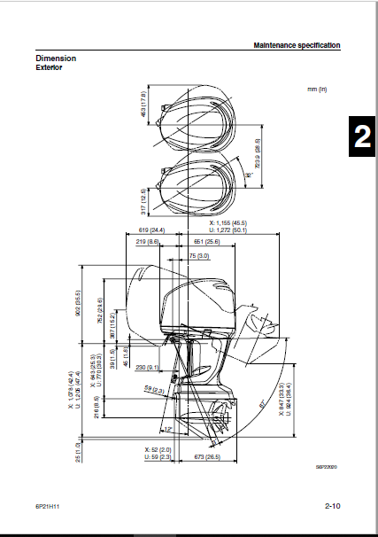
Dimension 2-10
Disassembling the cylinder block 5-58
Disassembling the drive shaft
housing 6-14, 6-43
Disassembling the forward gear 6-14
Disassembling the gear pump 7-34
Disassembling the lower case 6-14, 6-43
Disassembling the oil pan 7-10
Disassembling the oil pump 5-66
Disassembling the propeller
shaft assembly 6-8
Disassembling the propeller
shaft housing 6-8, 6-36
Disassembling the PTT motor 7-28
Disassembling the reverse gear 6-43
Disassembling the starter motor 8-40
Disassembling the tilt cylinder and
trim cylinder 7-39
Disassembling the upper case 7-10
Disassembly and assembly 1-5
Disconnecting the quick connector 4-9
Draining the fuel4-9
Drive shaft and lower case
(counter rotation model)6-41
Drive shaft and lower case
(regular rotation model)6-12
E
ECM5-36
ECM and electronic throttle valve
control system8-23
ECM system1-13
Electrical 2-7
Electrical component8-3
Electronic fuel injection control system1-25
Electronic throttle valve control system1-40
Engine speed control system1-43
Exhaust cover 5-39
F
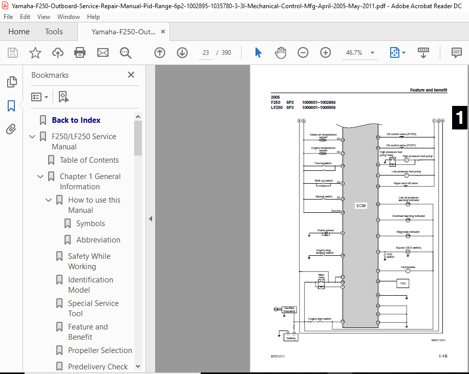
Feature and benefit1-13
Fire prevention 1-4
Fuel control system8-34
Fuel filter 4-11
Fuel hose and blowby hose 4-1
Fuel injector 4-26
Fuel system3-3
Fuse box 5-37
Fuse holder 8-5
G
Gear pump 7-31
General 3-14
General specification 2-1
General torque 2-15
Good working practice 1-5
H
Hose routing4-1
How to use this manual1-1
I
Identification1-6
Ignition and ignition control system8-17
Ignition timing control system1-29
Installing the camshaft, driven sprocket,
and timing belt5-28
Installing the clamp bracket 7-19
Installing the cooling water
passage cover5-50
Installing the cylinder head 5-51
Installing the drive shaft 6-16, 6-46
Installing the exhaust cover 5-40
Installing the fuel hose clamp 4-25
Installing the fuel injector 4-27
Installing the intake manifold 4-13
Installing the intake silencer 4-13
Installing the lower unit 6-19, 6-49
Installing the power unit 5-74
Installing the propeller shaft
housing 6-17, 6-47
Installing the PTT motor 7-43
Installing the PTT unit 7-19
Installing the reservoir 7-44
Installing the steering arm 7-14
Installing the throttle body 4-18
Installing the tilt cylinder 7-42
Installing the tilt ram 7-44
Installing the trim ram 7-42
Installing the upper case 7-13
Installing the valve 5-48
Installing the water pump and
shift rod6-18, 6-48
Installing the wiring harness 5-72
Intake manifold 4-12
Introduction 9-1
J
Junction box 5-38
K
Knock control system 1-32
L
Lower unit 1-47, 2-6, 3-13
Lower unit (counter rotation model) 6-29
Lower unit (regular rotation model) 6-1
Low-pressure fuel pump 4-20
Lubricating the outboard motor 3-16
M
Maintenance interval chart 3-1
Maintenance specification 2-3
Manual format 1-1
Measuring the forward and
reverse gear backlash 6-26, 6-56
Measuring the fuel pressure 4-7
Measuring the peak voltage 8-1
Model 1-6
P
Part, lubricant, and sealant 1-4
Port view8-3, 8-9
Index
i-4 6P21H11
Power unit 2-3, 3-4, 5-1
Predelivery check1-49
Propeller selection 1-48
Propeller shaft housing
(counter rotation model)6-34
Propeller shaft housing
(regular rotation model)6-6
Propeller size 1-48
PTT electrical system7-46
PTT motor 7-27
PTT unit 7-22
R
Reducing the fuel pressure 4-8
Refacing the valve seat5-46
Removing the clamp bracket 7-19
Removing the cooling water
passage cover5-49
Removing the cylinder head 5-43
Removing the drive shaft 6-14, 6-43
Removing the exhaust cover 5-40
Removing the fuel hose clamp4-25
Removing the lower unit 6-4, 6-32
Removing the power unit 5-22
Removing the propeller shaft
housing assembly 6-8, 6-36
Removing the PTT unit 7-18
Removing the steering arm7-14
Removing the timing belt,
driven sprocket, and camshaft 5-24
Removing the upper case 7-10
Removing the water pump
and shift rod 6-4, 6-33
Removing the wiring harness guide5-20
Replacing the oil filter3-6
Replacing the timing belt5-15
Replacing the valve guide5-45
S
Safety while working 1-4
Selecting the connecting rod bearing5-63
Selecting the forward gear shim 6-23, 6-54
Selecting the main bearing 5-65
Selecting the pinion shim 6-22, 6-52
Selecting the propeller shaft shim 6-25, 6-55
Selecting the reverse gear shim 6-24, 6-53
Selection 1-48
Self-protection1-4
Serial number1-6
Shift rod and bottom cowling7-1
Shimming 6-22, 6-52
Shimming (counter rotation model)6-51
Shimming (regular rotation model) 6-21
Special service tool 1-7
Specified torque 2-12
Starboard view8-4, 8-11
Starter motor 8-38
Starter motor and accelerator
position sensor 5-35
Starting system 8-36
Symbol 1-2
T
Test run 1-52
Throttle body 4-15
Tightening torque 2-12
Tilt cylinder and trim cylinder 7-37
Top cowling 3-3
Top view 8-8, 8-16
Trouble code and checking step 9-7
Troubleshooting the lower unit 9-23
Troubleshooting the power unit 9-5
Troubleshooting the power unit
(trouble code not detected) 9-17
Troubleshooting the power unit
using the diagnostic test lead 9-15
Troubleshooting the power unit
using the YDIS 9-5
Troubleshooting the PTT unit 9-22
U
Upper case and steering arm 7-5
V
Vapor gas hose 4-2
Vapor separator 4-22
Variable camshaft timing control
system 1-35, 8-32
Ventilation 1-4
W
Wiring harness routing 8-9
Y
YDIS 9-1
PLEASE NOTE:
- This is the same manual used by the dealers to diagnose and troubleshoot your vehicle
- You will be directed to the download page as soon as the purchase is completed. The whole payment and downloading process will take anywhere between 2-5 minutes
- Need any other service / repair / parts manual, please feel free to contact [email protected] . We still have 50,000 manuals unlisted


