

Wacker Neuson WL44 WL54 Wheel loader Service Manual – PDF DOWNLOAD
IMAGES PREVIEW OF THE MANUAL:

DESCRIPTION:
Wacker Neuson WL44 WL54 Wheel loader Service Manual – PDF DOWNLOAD
Use of the service manual
- The purpose of this service manual is to help maintain the constant operation readiness of the machine. This ensures the high value of the machine through careful maintenance and after-sales monitoring.
- The experiences of our factory personnel and service technicians are summarized in this service manual. Every sequence of images shows the procedure of a repair process. The provided text contains necessary instructions for adjustment, application of special tools, etc. Major repair procedures are described in such a way that smaller subtasks can also be
- performed individually following the respective procedures. The manual is appended according to further technical development of the machines and therefore is kept up-to-date to serve as a reference.
- For reasons of safety and security, always compare the specified values and capacities with the latest Operator’s Manual of the respective machine. Technical data, dimensions and weights are only given as an indication. Responsibility for errors or omissions not accepted. Deviations of images are possible
TABLE OF CONTENTS:
Wacker Neuson WL44 WL54 Wheel loader Service Manual – PDF DOWNLOAD
E Introduction
E1 Notice on this service manual E-1
Use of the service manual E-2
Explanation of symbols and abbreviations E-3
Repair instructions E-4
E2 Technical data E-5
Engine E-5
Permissible inclination E-6
Traveling drive/axles E-6
Machine-travel hydraulics E-6
Brakes E-7
Tires E-7
Steering system E-8
Operating hydraulics E-8
Coolant E-9
Vibration E-10
Weights E-10
Payload/load-carrying capacity/lift capacity E-11
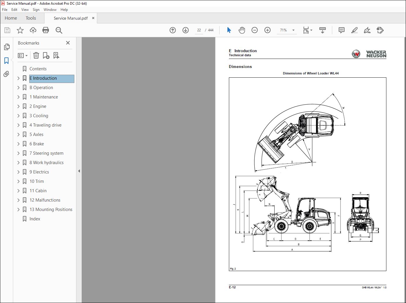
Dimensions E-12
E3 Tightening torques E-16
General tightening torques E-16
Specific tightening torques E-16
Torque values for metric coarse-pitch thread E-17
Torque values for metric fine-pitch thread E-18
Tightening torques for hydraulic screw connections and air-conditioning screw connections with
sealing cone and O-ring DIN 3865 E-19
Tightening torques for hydraulic screw connections with olive DIN 3861 E-20
Tightening torques for hydraulic system screw-in spud SDS E-21
Tightening torques for hydraulics rotating threaded fittings E-24
Tightening torques for banjo bolts DIN 7643 E-24
Tightening torques for adjustable hydraulics screw-in spuds SDE E-25
Tightening torques for brake line threaded fittings E-27
Tightening torques for worm drive hose clamps E-27
Tightening torques for spring-loaded worm drive hose clamps E-27
E4 Safety instructions E-28
Pay particular attention to the following E-28
Safety symbols and signal words E-28
Safety and Accident Prevention Regulations E-29
Safety instructions for repair work E-30
Safety instructions for work on the engine E-33
Safety instructions for work on the hydraulic system E-34
Safety instructions for work on the air conditioning system E-36
Safety instructions for work on traveling drive and axles E-36
Safety instructions for work on the braking system E-36
Safety instructions for work on the frame E-36
Safety instructions for work on the electrical system E-38
Safety instructions for work on the wheels E-38
E5 Special tools E-39
Claws and extractors E-39
Clamp E-39
I-2 SHB WL44 / WL54 * 10 * [en]
I
B Operation
B1 Overview of control elements B-1
Control and display elements B-1
Comfort cabin control and display instruments B-3
Indicating instruments B-5
Loader unit control lever B-6
Overview of rotary switches B-7
Overview of the toggle switch panel of the operator’s canopy and standard cabin B-7
Overview of the toggle switch panels for comfort cabin B-10
B2 Indicator lights and warning lights (overview) B-12
1 Maintenance
11 Information on maintenance 1-1
Responsibilities and prerequisites 1-1
Safety instructions 1-1
Battery master switch 1-5
12 Maintenance overview 1-6
Daily/weekly maintenance 1-6
Inspection schedules 1-7
Inspection intervals 1-10
13 Lubrication plan 1-13
14 Fluids and lubricants 1-15
Fluids and lubricants (overview) 1-15
Perkins engine 404D-22 (357 kW) 1-15
Perkins engine 404F-22 (447 kW) 1-16
Deutz engine TD 2011 (551 kW) 1-16
Deutz engine TCD 29 L4 (554 kW) 1-16
15 Maintenance accesses 1-17
Opening the engine cover 1-17
Remove / install driver’s seat 1-18
Removing/installing the footwell cover panel 1-18
Removing/installing cover for rear wall cladding 1-19
Removing/installing cover for control console (Standard Cabin) 1-19
Removing/installing rear side cover (Comfort Cabin) 1-19
Opening the side maintenance hatch (Comfort Cabin) 1-19
Open the battery holder (for Perkins engine) 1-20
16 Cleaning and maintenance 1-21
Information on cleaning and maintenance 1-21
Information on cleaning 1-22
General safety check 1-22
17 Lubrication work 1-23
Lubrication 1-23
Lubricating with the central lubrication system (option) 1-23
Central lubrication system diagram 1-26
Installing the high-pressure hoses on the central lubrication system 1-27
Instructions for troubleshooting in case of central lubrication system blocking 1-28
Repairing a blocking distributor of the central lubrication system 1-29
Troubleshooting table for central lubrication system 1-30
18 Fuel system 1-31
Information on the fuel system 1-31
Fuel system 1-32
Refueling with diesel fuel 1-32
Water separator maintenance 1-34
Replace the filter element of the fuel filter (Perkins engine) 1-35
Replace the fuel filter (Perkins engine) 1-37
Replace the fuel filter (Deutz engine) 1-39
Replace the fuel pre-filter (Deutz engine) 1-40
SHB WL44 / WL54 * 10 * [en] I-3
I
Bleeding the fuel system 1-40
19 Engine lubrication system 1-41
Replace the engine oil and engine oil filter 1-41
110 Cooling system 1-43
Information on the cooling system 1-43
Information on the coolant 1-43
Checking/adding/changing coolant 1-44
Checking the antifreeze mixture 1-45
Cleaning the cooling system 1-46
111 Air filter 1-48
Information on the engine air filter system 1-48
Engine air filter dust valve 1-49
Engine air filter 1-49
112 V-belt/toothed belt 1-51
Information on the V-belt 1-51
Checking the V-belt tension / tensioning the V-belt 1-52
Note on toothed belts 1-53
113 Hydraulic system 1-54
Information on the hydraulic system 1-54
Change the ventilation filter 1-55
Information on hydraulic oil 1-56
Checking the hydraulic oil level 1-56
Adding hydraulic oil 1-57
Changing hydraulic oil 1-57
Replacing the hydraulic oil filter insert 1-58
Replacing filter insert of high-pressure filter 1-58
Bleeding the hydraulic system 1-59
114 Electrical system 1-60
Information on the electrical system 1-60
Fuses 1-60
Information on the battery 1-61
Removing the battery 1-61
Battery maintenance 1-62
Starting aid and jump-starting 1-63
115 Heating, ventilation and air conditioning system (option) 1-65
Heating maintenance 1-65
Maintenance of cabin breather filter 1-65
Maintenance of air conditioning (option) 1-66
116 Washer system 1-67
Filling up the washer system reservoir 1-67
117 Axles/traveling drive 1-68
Checking and replacing the axle oil 1-68
118 Braking system 1-70
Information on the braking system 1-70
119 Tires 1-71
Information on tires 1-71
Inflating the tires 1-72
Wheel change 1-73
Checking the liquid level of the tires 1-73
Ballasting wheels with liquid 1-74
120 Maintenance and servicing work on attachments 1-75
121 Maintenance of options 1-76
Automatic trailer coupling 1-76
122 Exhaust gas treatment 1-77
Notes about the exhaust gas treatment with diesel particulate filter 1-78
Diesel particulate filter regeneration
Perkins engine/404F-22T (447 kW) 1-79
I-4 SHB WL44 / WL54 * 10 * [en]
I
Changing the crankcase vent filter (Perkins 404F-22T only) 1-87
Diesel particulate filter regeneration
Deutz engine TCD 29 L4 (554 kW) 1-88
Diesel oxidation catalytic converter
Deutz engine TCD 29 L4 (554 kW) 1-97
2 Engine
21 Perkins engine 404D-22 (357 kW) 2-1
Overview 2-2
Adjust idle speed 2-5
22 Perkins engine 404F-22 (447 kW) 2-6
Overview 2-6
Removing/installing the engine 2-8
23 Alternator (447 kW) 2-12
Removing the alternator V-belt 2-12
Removing the alternator 2-12
24 Starter M001 (447 kW) 2-13
Removing/installing the starter 2-13
25 Diesel particulate filter (447 kW) 2-14
26 Deutz engine TCD 29 L4 (554 kW) 2-15
Overview 2-15
Lube oil system 2-17
Exhaust gas recirculation 2-18
Exhaust-gas treatment 2-19
Electronic engine control unit 2-20
Removing/installing the engine 2-21
27 V-belts (554 kW) 2-27
V-belt of fan 2-27
Alternator V-belt 2-27
28 Alternator (554 kW) 2-28
29 Removing/installing the starter (554 kW) 2-29
210 Removing/installing the air filter (554 kW) 2-30
211 Deutz engine TD2011 L04w (551 kW) 2-31
Overview 2-31
Lube oil system 2-34
212 Removing/installing the fuel tank 2-36
3 Cooling
31 Removing/installing the coolant reservoir 3-1
32 Removing/installing the radiator 3-2
33 Removing/installing fan blades 3-5
4 Traveling drive
41 Traveling drive hose routing (example) 4-1
42 Variable displacement pump 4-2
Overview A4VG56DA (20 km/h version) 4-2
Overview A4VG71DA (30 km/h version) 4-3
Pressure values A4VG56DA (20 km/h version) 4-4
Pressure values A4VG71DA (30 km/h version) 4-5
Checking/adjusting the pressure cutoff 4-6
Checking/adjusting the inching 4-7
Checking/adjusting the starting speed 4-7
Checking low pressure (supply pressure) 4-8
Checking the high pressure of the variable displacement pump 4-8
Checking the setting pressure of the variable displacement pump 4-9
Checking/adjusting the mechanical zero position 4-10
Removing/installing the variable displacement pump 4-11
SHB WL44 / WL54 * 10 * [en] I-5
I
43 Variable displacement motor 4-14
Overview 4-14
Checking and adjusting the control initiation of the variable displacement motor 4-15
Removing/installing the variable displacement motor 4-16
44 Hydraulic oil reservoir 4-18
Removing/installing the hydraulic oil reservoir 4-18
Removing/installing the return filter 4-19
Removing/installing the temperature switch 4-19
45 Removing/installing the cardan shaft 4-20
46 Troubleshooting 4-22
No forward or reverse travel 4-22
Machine travel starts too early 4-23
Machine travel starts too late 4-24
Severe engine droop 4-25
Not enough traction force 4-26
Travel speed is not reached 4-27
5 Axles
51 Front axle 5-1
Overview 5-1
Removing/installing the front axle 5-2
52 Rear axle 5-5
Overview 5-5
Removing/installing the rear axle 5-5
53 Type label – front/rear axle 5-9
6 Brake
61 Removing/installing the brake pedal 6-1
Standard cabin 6-1
Comfort cabin 6-2
62 Removing/installing the parking brake 6-4
Standard cabin 6-4
Comfort cabin 6-4
63 Removing/installing the parking brake Bowden cable 6-5
64 Master brake cylinder 6-6
Overview (20 kph version) 6-6
Removing/installing the master brake cylinder 6-7
7 Steering system
71 Hose routing 7-1
72 Removing/installing the steering wheel 7-2
73 Removing/installing the steering column 7-4
Standard cabin 7-4
Comfort cabin 7-4
74 Removing/installing steering column gas strut (Comfort Cabin) 7-6
75 Removing/installing steering cylinder A81 7-8
76 Steering orbitrol S1 7-10
Overview 7-10
Removing/installing the steering orbitrol 7-11
77 Gear pump 7-13
Overview 7-13
Checking the gear pump 7-13
Removing/installing the gear pump 7-15
8 Work hydraulics
81 Overview 8-1
Rear chassis (ex machines with protective roof/standard cabin) 8-2
82 Hose routing of lift, tilt and lock cylinders (WL44) 8-3
I-6 SHB WL44 / WL54 * 10 * [en]
I
83 Hoses of lift and tilt cylinders with counterbalance valve 8-4
WL44 8-4
WL54 8-5
84 High Flow hose routing 8-6
WL44 8-6
WL54 8-7
85 Hose routing for rear additional control circuit with control valve HDS21/1 for Deutz engines
(WL44 / WL54) 8-8
86 Hose routing for rear additional control circuit with control valve HDS21/1 for Perkins engines
(WL44) 8-9
87 Hose routing for rear additional control circuit with control valve HDS21/2 for Deutz engines
(WL44 / WL54) 8-10
88 Hose routing for rear additional control circuit with control valve HDS21/2 for Perkins engines
(WL44) 8-11
89 Removing/installing gear pump P43/P57 8-12
810 Removing/installing lock cylinder A4 8-13
811 Removing/installing the lock pin 8-14
812 Removing/installing the tilt cylinder 8-15
813 Removing/installing the loader unit 8-17
814 Removing/installing the lift cylinder 8-19
815 Removing/installing the reversing lever 8-21
816 Removing/installing solenoid valve V30 8-22
817 Removing/installing vibration damping valve V75 8-23
818 Removing/installing the quickhitch 8-24
819 Removing/installing operation lever for additional hydraulic system (control lever) 8-25
820 Control valve 8-26
Checking and adjusting working pressure 8-26
Removing/installing the control valve 8-27
821 Removing/installing control valve for additional hydraulics system 8-30
822 Designation of hydraulic components 8-31
823 Hydraulics diagram for wheel loaders WL44 – HDM19/4 with HDS21/1 or 6/2 directional valve 8-33
824 Hydraulics diagram for wheel loaders WL44 – HDM19/4 with HDS21/2 8-35
825 Hydraulics diagram for wheel loaders WL44 – HDM19/3 with HDS21/1 or 6/2 directional valve 8-37
826 Hydraulics diagram for wheel loaders WL44 – HDM19/4 High Flow 8-39
827 Hydraulics diagram for wheel loaders WL54 – HDM19/4 with HDS21/1 or 6/2 directional valve 8-41
828 Hydraulics diagram for wheel loaders WL54 – HDM19/4 with HDS21/2 8-43
829 Hydraulics diagram for wheel loaders WL54 – HDM19/3 with HDS21/1 or 6/2 directional valve 8-45
830 Hydraulics diagram for wheel loaders WL54 – HDM19/4 High Flow 8-47
9 Electrics
91 Fuses 9-1
92 Fuse assignment 9-2
93 Removing/installing the machine control unit 9-6
Disassemble 9-6
Install 9-7
94 Joystick 9-11
Overview 9-11
Removing/installing the joystick 9-12
95 Removing/installing the battery master switch 9-14
96 Malfunctions of the machine electronics 9-15
Error message on display with symbol 9-15
Error codes 9-16
97 Electrical diagram – Electronics, power supply (FG01-01) 9-17
98 Electrical diagram – Electronics CAN Bus (FG01-02) 9-18
99 Electrical diagram – Perkins engine 404D-22 (FG02-01) 9-19
910 Electrical diagram – Perkins engine 404F-22 (FG02-02) 9-20
911 Electrical diagram – Perkins engine 404F-22 (FG02-03) 9-21
SHB WL44 / WL54 * 10 * [en] I-7
I
912 Electrical diagram – Deutz engine TD2011 (FG02-04) 9-22
913 Electrical diagram – Deutz engine TCD29 (FG02-05) 9-23
914 Electrical diagram – Deutz engine TCD29 (FG02-06) 9-24
915 Electrical diagram – Deutz engine TCD29 DPF (FG02-07) 9-25
916 Electrical diagram – Deutz engine TCD29 DPF (FG02-08) 9-26
917 Electrical diagram – Deutz engine TCD29 DPF (FG02-09) 9-27
918 Electrical diagram – Instrument (FG03-01) 9-28
919 Electrical diagram – Drive function (FG04-01) 9-29
920 Electrical diagram – manual throttle, manual inching (FG04-02) 9-30
921 Electric circuit diagram – Working lights; Rotating beacon; Horn (FG05-01) 9-31
922 Electric circuit diagram – Light StVZO (German traffic regulations) (turn indicator system, horn)
(FG06-01) 9-32
923 Electric circuit diagram – Light StVZO (German traffic regulations) (front headlight) (FG06-02) 9-33
924 Electric circuit diagram – Light (brake light, reversing light) (FG06-03) 9-34
925 Electrical diagram – Washer system (FG07-01) 9-35
926 Electric circuit diagram – Radio, cigarette lighter, interior light (FG08-01) 9-36
927 Electric circuit diagram – Heating; Seat (FG09-01) 9-37
928 Electric circuit diagram – Heating; Air conditioning system (FG09-02) 9-38
929 Electric circuit diagram – Hydraulic control circuits, E-connection 12 V (FG10-01) 9-39
930 Electric circuit diagram – Hydraulic control circuits, rear E-connection (FG11-01) 9-40
931 Electrical diagram – High Flow (FG11-02) 9-41
932 Electric circuit diagram – Roll-in stop; Overload display (FG11-03) 9-42
933 Electrical diagram – Loader unit stabilizer, counterbalance valve (FG11-04) 9-43
934 Electrical diagram – Central lubrication system (FG12-01) 9-44
935 Designation of electrical components 9-45
Component list 9-45
Cable colors 9-52
10 Trim
101 Removing/installing the engine cover 10-1
102 Removing/installing the base plate 10-2
103 Removing/installing the trailer power outlet 10-3
104 Removing/installing the trailer coupling/chassis cover 10-4
105 Removing/installing the counterweight 10-6
106 Base weights (WL54) 10-8
11 Cabin
111 Removing/installing the floor mat 11-1
Standard cabin 11-1
Comfort cabin 11-1
112 Removing/installing the steering wheel 11-2
113 Removing/installing the indicating instrument 11-4
114 Removing/installing the starter 11-6
115 Removing/installing the wiper motor 11-8
Standard cabin 11-8
Comfort cabin 11-9
116 Heating 11-11
Removing/installing the heating blower 11-11
Remove/install heater box 11-15
117 Removing/installing the cabin 11-17
Standard cabin 11-17
Comfort cabin 11-19
118 Removing/installing the base plate 11-20
I-8 SHB WL44 / WL54 * 10 * [en]
I
12 Malfunctions
121 Towing a machine 12-1
Preparations for towing 12-1
Towing the machine 12-2
After towing 12-2
122 Error code lists 12-3
Engine control unit Perkins 404F 12-3
Machine control unit TTC77 12-7
Engine control unit Deutz TCD29 12-12
13 Mounting Positions
131 Hydraulics 13-1
V04 – Priority valve 13-1
V30 / V109 – 2/2 directional valve for lock cylinder 13-1
V34 – HighFlow valve 13-2
V50 – Inching valve 13-3
V66 / V67 – Control valve 13-4
V72 – Magnetic valve Differential lock 13-4
V75 – Vibration damping valve 13-5
V80 – 6/2 directional valve 13-5
V124 / V126 / V127 – Control valve 13-6
V128 – 2/2 directional valve (Roll-in stop) 13-6
132 Electrics 13-7
B001 – Fuel indicator 13-7
B015 – Coolant level sensor 13-7
K001 – High current relay 13-8
K002 – Relay F026, F027, F028 13-8
K005 – High current relay for preheating 13-9
K006 – Preheating relay 13-10
K007 – High current relay for start 13-11
K010 – Turn indicator relay 13-11
K011 – Air conditioning relay (comfort cabin only) 13-12
K042 – Engine electronics switching relay 13-12
K058 – 1st/2nd speed switching relay 13-13
K076 – Relay F029-F036 13-13
K088 – Fuel pump switching relay 13-14
K089 – Switching relay DPF pump
K090 – Switching relay DPF glow plug 13-15
K109 – Roll-in stop relay 13-15
K112 – Manual inching switching relay
K138 – Switching relay High Flow pressure relief 13-16
R018 – Bus terminating resistor (Perkins 404D-22, Deutz TD2011 engine) 13-17
R810, R813 – Bus terminating resistors (Deutz TCD29 engine) 13-18
R812 – Bus terminating resistor (Deutz TCD29 engine) 13-19
S006 – Temperature switch for hydraulic oil
VIDEO PREVIEW OF THE MANUAL:
PLEASE NOTE:
- This is the same manual used by the DEALERSHIPS to SERVICE your vehicle.
- The manual can be all yours – Once payment is complete, you will be taken to the download page from where you can download the manual. All in 2-5 minutes time!!
- Need any other service / repair / parts manual, please feel free to contact us at heydownloadss @gmail.com . We may surprise you with a nice offer
S.M


