

Wacker Neuson WL38 Wheel loader Service Manual – PDF DOWNLOAD
IMAGES PREVIEW OF THE MANUAL:

DESCRIPTION:
Wacker Neuson WL38 Wheel loader Service Manual – PDF DOWNLOAD
Use of the service manual
- The purpose of this service manual is to help maintain the constant operation readiness of the machine.
- This ensures the high value of the machine through careful maintenance and after-sales monitoring.
- The experiences of our factory personnel and service technicians are summarized in this service manual.
- Every sequence of images shows the procedure of a repair process. The provided text contains necessary instructions for adjustment, application of special tools, etc.
- Major repair procedures are described in such a way that smaller subtasks can also be performed individually following the respective procedures.
- The manual is appended according to further technical development of the machines and therefore is kept up-to-date to serve as a reference.
- For reasons of safety and security, always compare the specified values and capacities with the latest Operator’s Manual of the respective machine.
- Technical data, dimensions and weights are only given as an indication. Responsibility for errors or omissions not accepted. Deviations of images are possible.
Information
Careful and prudent working is the best way to avoid accidents!
TABLE OF CONTENTS:
Wacker Neuson WL38 Wheel loader Service Manual – PDF DOWNLOAD
Introduction
E1 Notice on this service manual E-1
Use of the service manual E-2
Explanation of symbols and abbreviations E-3
Repair instructions E-4
E2 Technical data E-5
Engine E-5
Permissible inclination E-6
Traveling drive/axles E-7
Brakes E-8
Tires E-8
Steering system E-9
Operating hydraulics E-9
Coolant E-11
Noise emissions E-11
Vibration E-12
Weights E-12
Payload/load-carrying capacity/lift capacity E-13
Dimensions E-14
E3 Tightening torques E-16
General tightening torques E-16
Specific tightening torques E-16
Torque values for metric coarse-pitch thread E-17
Torque values for metric fine-pitch thread E-18
Tightening torques for hydraulic screw connections and air-conditioning screw connections with
sealing cone and O-ring DIN 3865 E-19
Tightening torques for hydraulic screw connections with olive DIN 3861 E-2
Tightening torques for hydraulic system screw-in spud SDS E-21
Tightening torques for hydraulics rotating threaded fittings E-24
Tightening torques for banjo bolts DIN 7643 E-24
Tightening torques for adjustable hydraulics screw-in spuds SDE E-25
Tightening torques for brake line threaded fittings E-27
Tightening torques for worm drive hose clamps E-27
Tightening torques for spring-loaded worm drive hose clamps E-27
E4 Safety instructions E-28
Pay particular attention to the following E-28
Safety symbols and signal words E-28
Safety and Accident Prevention Regulations E-29
Safety instructions for repair work E-3
Safety instructions for work on the engine E-33
Safety instructions for work on the hydraulic system E-34
Safety instructions for work on the air conditioning system E-36
Safety instructions for work on traveling drive and axles E-36
Safety instructions for work on the braking system E-36
Safety instructions for work on the frame E-36
Safety instructions for work on the electrical system E-38
Safety instructions for work on the wheels E-38
E5 Special tools E-39
Claws and extractors E-39
Clamp E-39
I-2 SHB WL38 * 2 * [en]
I
B Operation
B1 Overview of control elements B-1
Control and display elements B-1
Indicating instruments (363 kW engine) B-3
Display instruments (357 kW / 447 kW and 554 kW engines) B-5
Loader unit control lever B-6
Overview of rotary switches B-7
Overview of switch panels B-7
B2 Indicator lights and warning lights (overview) B-1
Description of indicator lights and warning lights (363 kW engine) B-1
Description of indicator lights and warning lights (357 / 447 kW and 554 kW engines) B-14
1 Maintenance
11 Information on maintenance 1-1
Responsibilities and prerequisites 1-1
Safety instructions 1-1
Battery master switch 1-5
12 Maintenance overview 1-6
Daily/weekly maintenance 1-6
Inspection schedules 1-7
Inspection intervals 1-1
13 Lubrication plan 1-13
14 Fluids and lubricants 1-15
Fluids and lubricants (overview) 1-15
Perkins engine 44D-22 (363 kW) 1-15
Perkins engine 44F-22 (357 kW)/44F-22T (447 kW) 1-16
Deutz engine TCD 29 L4 (554 kW) 1-16
15 Maintenance accesses 1-17
Maintenance openings 1-17
Raising the cabin sideways 1-18
16 Cleaning and maintenance 1-19
Information on cleaning and maintenance 1-19
Information on cleaning 1-2
General safety check 1-2
17 Lubrication work 1-21
Lubrication 1-21
Lubricating with the central lubrication system (option) 1-21
Central lubrication system diagram 1-24
Installing the high-pressure hoses on the central lubrication system 1-25
Instructions for troubleshooting in case of central lubrication system blocking 1-26
Repairing a blocking distributor of the central lubrication system 1-27
Troubleshooting table for central lubrication system 1-28
18 Fuel system 1-29
Information on the fuel system 1-29
Fuel system 1-3
Refueling with diesel fuel 1-3
Performing fuel filter maintenance 1-32
Replace the filter element of the fuel filter (Perkins engine) 1-33
Replace the fuel filter (Perkins engine) 1-35
Replace the fuel filter (Deutz engine) 1-37
Replace the fuel pre-filter (Deutz engine) 1-38
Bleeding the fuel system 1-39
19 Engine lubrication system 1-4
Replace the engine oil and engine oil filter 1-4
SHB WL38 * 2 * [en] I-3
I
11 Cooling system 1-41
Information on the cooling system 1-41
Information on the coolant 1-41
Check / top off / replace the cooling liquid 1-42
Checking the antifreeze mixture 1-43
Cleaning the cooling system 1-43
111 Air filter 1-45
Information on the engine air filter system 1-45
Engine air filter dust valve 1-46
Engine air filter 1-46
112 V-belt / toothed belt 1-48
Information on the V-belt 1-48
Checking the V-belt tension / tensioning the V-belt 1-49
Notes about tooth belts 1-49
113 Hydraulic system 1-5
Information on the hydraulic system 1-5
Replace the breather filter 1-51
Information on hydraulic oil 1-52
Checking the hydraulic oil level 1-52
Adding hydraulic oil 1-53
Changing hydraulic oil 1-53
Replace the filter element of the hydraulic oil return filter 1-54
Replace the air cleaner (filter) element of the high pressure filter 1-54
Bleeding the hydraulic system 1-55
114 Electrical system 1-56
Information on the electrical system 1-56
Fuses 1-56
Information on the battery 1-57
Removing the battery 1-57
Starting aid and jump-starting 1-59
115 Heating, ventilation and air conditioning system (option) 1-61
Heating (option) maintenance 1-61
Maintenance of cabin breather filter 1-61
Maintenance of air conditioning (option) 1-61
116 Washer system 1-62
Filling up the washer system reservoir 1-62
117 Axles/traveling drive 1-63
Checking and replacing the axle oil 1-63
118 Braking system 1-65
Information on the braking system 1-65
119 Tires 1-66
Information on tires 1-66
Inflating the tires 1-67
Wheel change 1-68
Checking the liquid level of the tires 1-69
Ballasting wheels with liquid 1-69
12 Maintenance and servicing work on attachments 1-7
121 Maintenance of options 1-71
Automatic trailer coupling 1-71
122 Exhaust gas treatment of Perkins 44F engine 1-72
Information on exhaust gas treatment 1-72
Regeneration of diesel particulate filter 1-73
123 Exhaust gas treatment of engine Deutz TCD 29 L4 (554 kW) 1-77
I-4 SHB WL38 * 2 * [en]
I
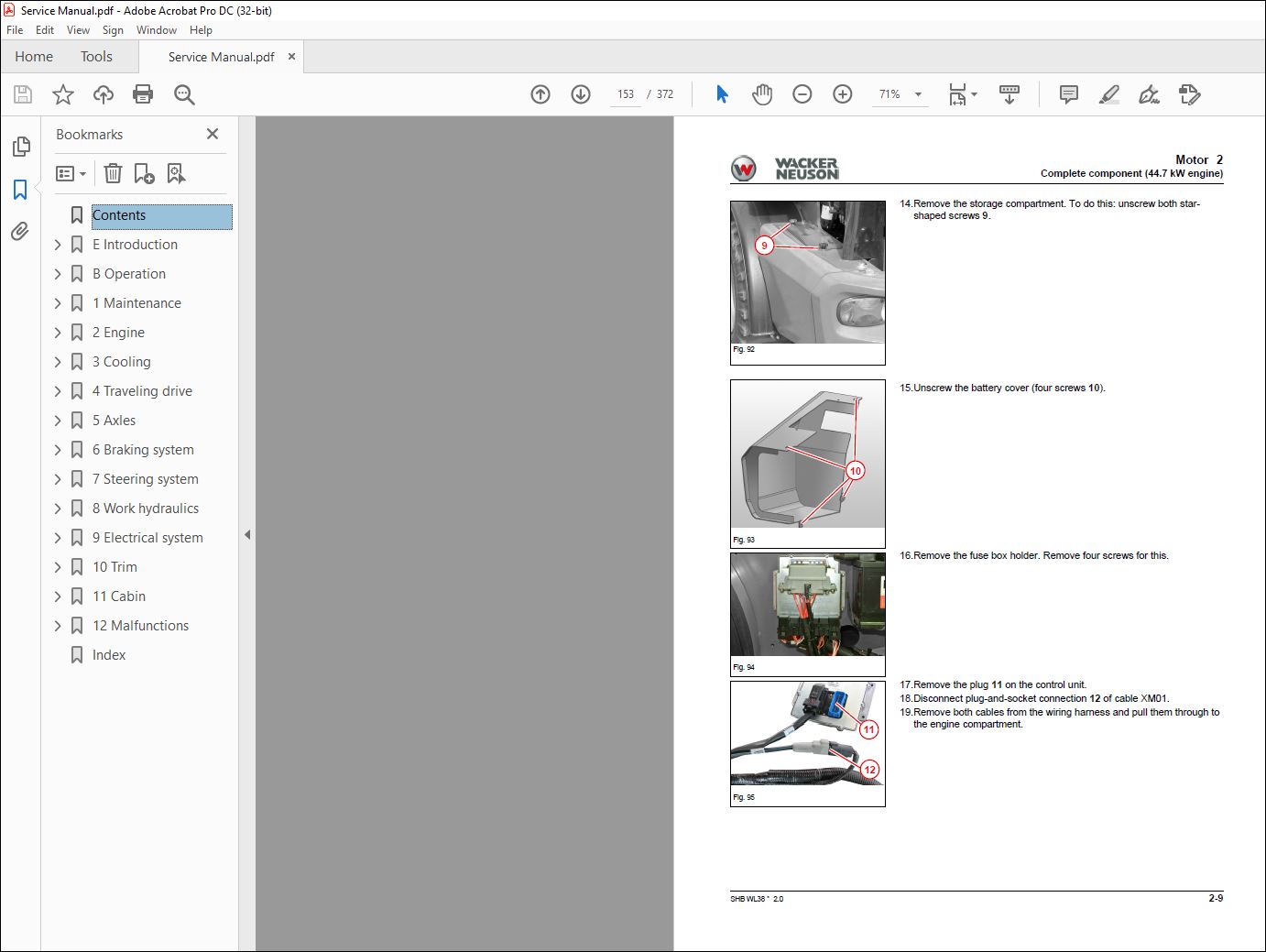
2 Engine
21 Complete component (363 kW engine) 2-1
Overview 2-2
22 Complete component (447 kW engine) 2-5
Overview 2-5
Removing/installing the engine 2-7
23 Alternator (447 kW) 2-13
Removing the alternator V-belt 2-13
Removing the alternator 2-13
24 Starter M1 (447 kW) 2-14
Removing/installing the starter 2-14
25 Diesel particulate filter (447 kW) 2-15
26 Complete component (Deutz engine 554 kW) 2-16
Overview 2-16
Lube oil system 2-18
Exhaust gas recirculation 2-19
Exhaust-gas treatment 2-2
Electronic engine control unit 2-21
Removing/installing the engine 2-22
27 V-belt (554 kW) 2-26
V-belt of fan 2-26
V-belt of the alternator 2-26
28 Alternator (554 kW) 2-27
29 Removing/installing the starter motor (554 kW) 2-28
21 Removing/installing the fuel tank 2-29
3 Cooling
31 Removing/installing the coolant reservoir 3-1
32 Removing/installing the radiator 3-2
33 Removing/installing fan blades 3-4
4 Traveling drive
41 Traveling drive hose routing 4-1
42 M-Drive hose routing 4-2
43 Variable displacement pump 4-3
Overview 4-3
Pressures 4-4
Checking/adjusting the pressure cutoff 4-5
Checking/adjusting the inching 4-6
Checking/adjusting the starting speed 4-6
Checking low pressure (supply pressure) 4-7
Checking the high pressure of the variable displacement pump 4-7
Checking the setting pressure of the variable displacement pump 4-8
Checking/adjusting the mechanical zero position 4-9
Removing/installing the variable displacement pump 4-11
44 Variable displacement motor M5 4-13
Overview 4-13
Checking and adjusting the control initiation of the variable displacement motor 4-14
Removing/installing the variable displacement motor 4-15
45 Hydraulic oil tank Z55 4-17
Removing/installing the hydraulic oil reservoir 4-17
Removing/installing the return filter 4-18
Removing/installing the temperature switch 4-19
46 Removing/installing the cardan shaft 4-2
47 M-Drive (Option) 4-22
Pressure values 4-22
SHB WL38 * 2 * [en] I-5
I
48 Troubleshooting 4-23
No forward or reverse travel 4-23
Machine travel starts too early 4-24
Machine travel starts too late 4-25
Severe engine droop 4-26
Not enough traction force 4-27
Travel speed is not reached 4-28
5 Axles
51 Front axle 5-1
Overview 5-1
Removing/installing the front axle 5-2
52 Rear axle 5-5
Overview 5-5
Removing/installing the rear axle 5-5
53 Type label – front/rear axle 5-9
6 Braking system
61 Overview 6-1
62 Service/parking brake 6-2
Overview 6-2
Drum brake setup 6-3
Change brake jaws/wire rope adapter 6-4
Exchange the spring-loaded cylinder 6-8
63 Removing/installing the parking brake 6-11
64 Removing/installing the parking brake Bowden cable 6-11
65 Master brake cylinder 6-12
Overview 6-12
Removing/installing the master brake cylinder 6-13
7 Steering system
71 Hose routing 7-1
72 Removing/installing the steering wheel 7-2
73 Removing/installing the steering column 7-4
74 Removing/installing steering cylinder A1 7-5
75 Steering orbitrol S1 7-7
Overview 7-7
Removing/installing the steering orbitrol 7-8
8 Work hydraulics
81 Overview 8-1
82 Hose installation 8-2
Hoses of lift, tilt and lock cylinders 8-2
Hoses of lift and tilt cylinders with counterbalance valve 8-3
High Flow hose routing 8-4
83 Gear pump P45 8-5
Overview 8-5
Checking the gear pump 8-5
Removing/installing the gear pump 8-7
84 Removing/installing lock cylinder A4 8-8
85 Removing/installing the lock pin 8-11
86 Removing/installing the tilt cylinder 8-12
87 Removing/installing the loader unit 8-14
88 Removing/installing the lift cylinder 8-17
89 Removing/installing the reversing lever 8-19
Removing/installing the rear reversing lever 8-19
Removing/installing the front reversing lever 8-21
81 Removing/installing solenoid valve V3 8-22
811 Removing/installing pressure relief valve V6 8-23
I-6 SHB WL38 * 2 * [en]
I
812 Removing/installing the quickhitch 8-25
813 Removing/installing the control valve 8-26
814 Designation of hydraulic components 8-28
815 Hydraulics diagram – HDS21/4 with HDS21/1 or 6/2 multiple way valve 8-3
816 Hydraulics diagram – HDS21/4 with HDS21/2 8-32
817 Hydraulics diagram – HDS21/3 with HDS21/1 or 6/2-multiple way valve 8-34
818 Hydraulics diagram – HDS21/3 with HDS21/2 8-36
819 Hydraulics diagram – HDS21/4 High Flow 8-38
9 Electrical system
Fuses 9-1
Fuse assignment 9-1
91 Removing/installing the machine control unit 9-4
Removal 9-4
Installation 9-4
92 Joystick 9-9
Overview 9-9
Removing/installing the joystick 9-1
93 Malfunctions of the machine electronics 9-11
363 kW engine 9-11
357 kW / 447 kW and 554 kW engine 9-11
94 Electrical diagram – power supply 9-13
95 Electrical diagram – power supply for control electronics; Lighting of joystick 9-14
96 Electrical diagram — Deutz engine 9-15
97 Electrical diagram – Perkins engine 44F-22 9-17
98 Electrical diagram – Perkins engine 44D-22 9-19
99 Electrical diagram – Bauser LED instrument 9-2
91 Electrical diagram – Ciam instrument 9-21
911 Electrical diagram – Travel function 9-22
912 Electrical diagram – Lights according to StVZO (German road traffic licensing regulations) 9-23
913 Electrical diagram – Turn indicator system; Horn 9-25
914 Electrical diagram – Wiper/wash system 9-26
915 Electrical diagram – Working lights; Rotating beacon 9-27
916 Electrical diagram – E-connection (front & rear); Hydro Comfort; Addition A; Continuous operation
of the 3rd control circuit 9-28
917 Electrical diagram – Hydraulic system 9-29
918 Electrical diagram – Air conditioning; Seat 9-32
919 Electrical diagram – Radio; Cigarette lighter; Interior light; Safe load indicator 9-33
92 Designation of electrical components 9-34
Component list 9-34
Cable colours 9-4
1 Trim
11 Removing/installing the engine cover 1-1
12 Removing/installing the bottom plate 1-2
13 Removing/installing the trailer power outlet 1-3
14 Removing/installing the trailer coupling/chassis cover 1-4
15 Removing/installing the counterweight 1-6
11 Cabin
111 Removing/installing the operator seat 11-1
112 Removing/installing the indicating instrument 11-3
113 Removing/installing the starter 11-5
114 Removing/installing the tilt cylinder 11-6
115 Removing/installing the wiper motor 11-7
116 Heating 11-8
Removing/installing the heater fan 11-8
Removing/installing the heater box 11-9
117 Removing/installing the cabin 11-12
12 Malfunctions
121 Towing a machine 12-1
Preparations for towing 12-1
Towing the machine 12-2
After towing 12-2
122 Error code lists 12-3
Engine control unit Perkins 44F 12-3
Machine control unit TTC77 12-7
Motor controller Deutz TCD29 12-12
Index
A
Abbreviations E-3
Accident prevention regulations
General E-29
Adding hydraulic oil 1-53
Air conditioning
Removing the condenser 1-44
Air filter 1-45
Axle
Changing the gearbox oil 1-64
B
Battery
Emergency starting/jump-starting 1-59
Battery master switch 1-5
Brake
Change brake jaws/wire rope adapter 6-4
Drum brake setup 6-3
Removing/installing parking brake 6-11
Replace the spring-loaded cylinder 6-8
Braking system 6-1
C
Cabin
Remove 11-12
Cardan shaft
Installation 4-20
Remove 4-20
Check the hydraulic oil level 1-52
Checking the antifreeze mixture 1-43
Checking/cleaning/replacing the engine air filter 1-46
Cleaning and maintenance 1-19
Control elements
Overview B-1
Cooling 3-1
Cooling system 1-41
Checking the antifreeze mixture 1-43
Clean 1-43
Coolant compound table E-11
D
Designation
Electrical components 9-34
hydraulic components 8-28
Diagram 9-21
E
Electrical diagram
12 V power outlet 9-33
Addition A 9-28
Air conditioning 9-32
Ciam instrument 9-21
Continuous operation of the 3rd control circuit 9-28
Control electronics power supply 9-14
Deutz engine 9-15
E connection 9-28
Horn 9-25
Hydraulic system 9-29
Hydro Comfort 9-28
Interior light 9-33
LED Bauser instrument 9-20
Lighting of joystick 9-14
Lights according to StVZO (German road
traffic licensing regulations) 9-23
Perkins engine 404D-22 9-19
Perkins engine 404F 22 9-17, 9-18
Power supply 9-13
Radio 9-33
Rotating beacon 9-27
Safe load indicator 9-33
Seat 9-32
Travel function 9-22
Turn indicator system 9-25
Wiper/wash system 9-26
Working lights 9-27
Electrical system 1-56
Fuse assignment 9-1
Fuses and relays 1-56
Emergency starting/jump-starting 1-59
Engine
Remove the Deutz engine 2-22
Remove the Perkins engine 2-7
Engine cover
Remove 10-1
Error code table 12-12
Explanation of symbols E-3
F
Filling up the washer system reservoir 1-62
Fluids and lubricants 1-15
Fluids and lubricants (overview) 1-15
Front axle 5-1
Type label 5-9
Fuel tank 2-29
Remove 2-30
Fuse assignment 9-1
Index
S-2 SHB WL38 * 20
S Index
G
Gear pump
Function description 8-5
Remove 8-7
General safety check 1-20
General specifications
Accident prevention E-29
H
Handling
Repair manual E-2
Heating, ventilation and air conditioning system
(option) 1-61
Hydraulic oil reservoir
Remove 4-17
Hydraulic system 1-50
Breather filter 1-51
Hydraulic oil 1-51
Hydraulics diagram
HDS21/3 with HDS21/1 or 6/2 directional
valve 8-34
HDS21/3 with HDS21/2 8-36
HDS21/4 High Flow 8-38
HDS21/4 with HDS21/1 or 6/2 directional
valve 8-30
HDS21/4 with HDS21/2 8-32
I
Inflating the tires 1-67
Information on cleaning 1-20
Information on the hydraulic system 1-50
L
Lift cylinder
Remove 8-17
Lock cylinder
Installation 8-9
Remove 8-8
Lock pins
Installation 8-11
Remove 8-11
Lubrication work 1-21
M
Machine
Lubrication 1-21
Payload and axle load E-13
Weight E-12
Maintenance 1-1
Air conditioning 1-61
Attachments 1-70
Axles 1-63
Braking system 1-65
Cabin breather filter 1-61
Checking the brake-fluid level 1-65
Cleaning the condenser of the air conditioning
system 1-61
Electrical system 1-56
Engine air filter 1-46
Inflating the tires 1-67
Lubrication plan 1-13
Replace the engine oil and engine oil filter 1-40
Replace the fuel filter (Deutz engine) 1-37
Replace the fuel filter (Perkins engine) 1-35
Replace the fuel pre-filter (Deutz engine) 1-38
Tires 1-66
Washer system 1-62
Master brake cylinder
Function description 6-12
Installation 6-15
Remove 6-13
O
Opening the engine cover 1-17
P
Performing fuel filter maintenance 1-32
R
Raising the control stand sideways 1-18
Rear axle
Type label 5-9
Refueling with diesel fuel 1-30
Releasing residual pressure in the hydraulic
system E-35
Removing the battery 1-57
Removing/installing fan blades 3-4
Removing/installing the indicating instrument 11-3
Removing/installing the steering column 7-4
Repair instructions
Cause of damage E-4
Diesel engine E-4
Spare parts E-4
Technical data E-4
Repair manual
handling E-2
Replace the engine oil and engine oil filter 1-40
Replacing the coolant reservoir 3-1
Replacing the radiator 3-2
S
Safety E-28
Safety instructions E-28
Safety instructions for work on the hydraulic
system E-34
Screw dimensions E-16
Signal words E-28
Special tools
Claws and extractors E-39
Extractor and drive-in pins E-39
Spring-loaded cylinder 6-8
Steering cylinder
Remove 7-5
Steering orbitrol
Function description 7-7
Remove 7-8
SHB WL38 * 20 S-3
Index S
Steering wheel
Installation 7-3
Remove 7-2
T
Tightening torques
Adjustable hydraulics screw-in spuds E-25
Air-conditioning connections with a seal cone
and round ring E-19
Banjo bolts E-24
Brake line threaded fittings E-27
General E-16
Hydraulic connections with a cutting ring E-20
Hydraulic connections with a seal cone and
round ring E-19
Hydraulic system rotating threaded fittings E-24
Hydraulics screw-in spud E-21
Metric coarse-pitch thread E-17
Metric fine-pitch thread E-18
Specific E-16
Worm drive hose clamps E-27
Tilt cylinder
Remove 8-12
Traveling drive 4-1
V
V-belt/toothed belt 1-48
W
Washer system 1-62
Wheel change 1-68
VIDEO PREVIEW OF THE MANUAL:
PLEASE NOTE:
- This is not a physical manual but a digital manual – meaning no physical copy will be couriered to you. The manual can be yours in the next 2 mins as once you make the payment, you will be directed to the download page IMMEDIATELY.
- This is the same manual used by the dealers inorder to diagnose your vehicle of its faults.
- Require some other service manual or have any queries: please WRITE to us at [email protected]
S.M


