

Wacker Neuson SW24 SW28 ST35 ST45 Large Frame Skid Steer Loader / Compact Track Loader Service Manual – PDF DOWNLOAD
IMAGES PREVIEW OF THE MANUAL:
DESCRIPTION:
Wacker Neuson SW24 SW28 ST35 ST45 Large Frame Skid Steer Loader / Compact Track Loader Service Manual – PDF DOWNLOAD
Foreword
General
- This manual provides detailed information and procedures to safely repair and maintain the following: Wacker Neuson Large Frame Skid Steer Loader (SSL) and Compact Track Loader (CTL). This manual is intended to introduce and guide the user through the latest factory-approved troubleshooting and repair techniques and practices.
- Before you attempt to troubleshoot or make repairs, you must be familiar with the operation of this machine. Refer to the operator’s manual for specific information on these topics.
- THE INFORMATION CONTAINED IN THIS MANUAL IS BASED ON MACHINES MANUFACTURED UP TO THE TIME OF PUBLICATION. WACKER NEUSON RESERVES THE RIGHT TO CHANGE ANY OF THIS INFORMATION WITHOUT NOTICE
How to Use This Manual
This manual is designed to provide multiple ways to locate and access repair information. Read each section in its entirety before beginning a procedure. Proper understanding of machine operation and components is the key to successful diagnostics and repair. Make use of special information features within this manual in order to be better prepared to perform repairs. Always follow manual procedures and safety guidelines. Never take shortcuts.
TABLE OF CONTENTS:
Wacker Neuson SW24 SW28 ST35 ST45 Large Frame Skid Steer Loader / Compact Track Loader Service Manual – PDF DOWNLOAD
Foreword 3
Foreword 3
Safety 4
Introduction 4
Preparing for the Job 4
Service Training 4
Repair Person Qualifications 4
Personal Protective Equipment (PPE) 4
Personal Safety Measures 4
Precautions 4
Cleaning 4
Preparing Machine for Maintenance 5
General Maintenance Notes 5
Machine Modifications 5
Safety Symbols Found In This Manual 6
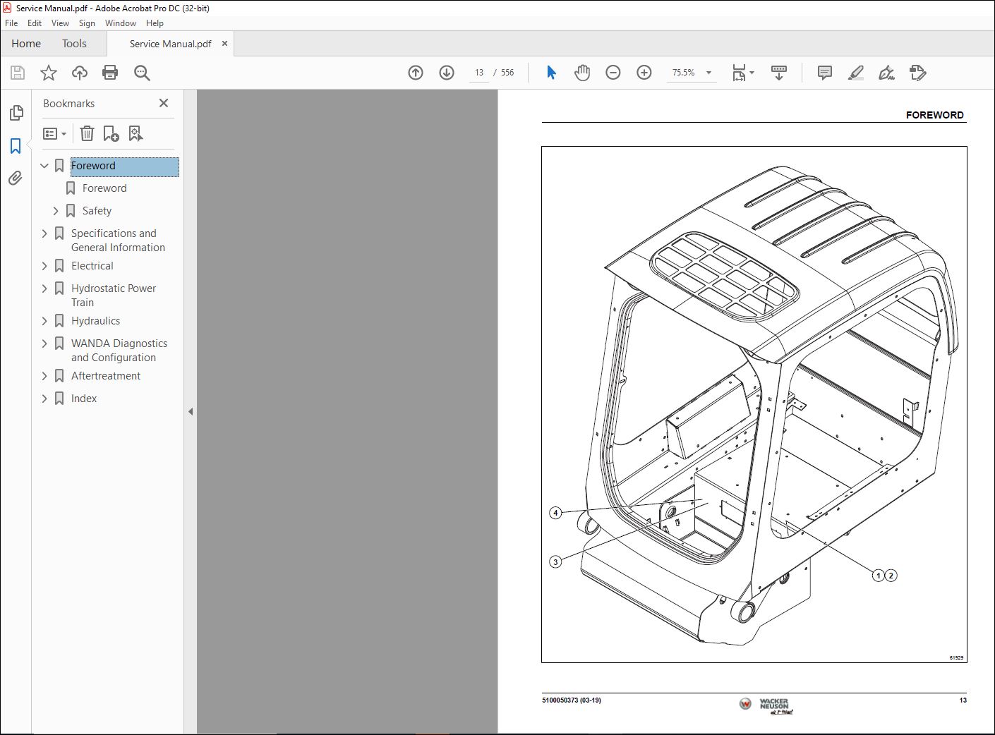
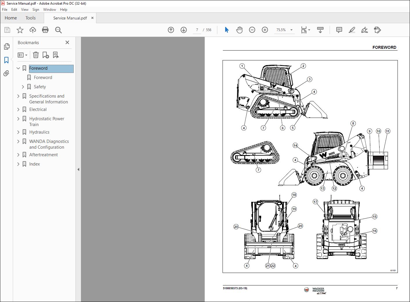
Safety Label Locations 6
Safety Label Inspection 14
Keep Work Area Clean 14
Keep Work Area Well Ventilated 15
Use Proper Eye and Face Protection 15
Park Machine Safely 15
Use Lifting Equipment Safely 15
Support Machine Securely 16
Use Compressed Air and Air
Tools Safely
16
Service Tires Safely 16
Handle Fuel Safely 16
Store Volatile and Hazardous Materials Safely 17
Handle Chemical Products Safely 17
Service Hydraulic System Safely 17
Service Cooling System Safely 17
Service Electrical Components
Safely
18
Dispose of Waste Materials
Safely
18
Specifications and General Information 21
Commonly Used Terms 22
Commonly Used Terms 22
Standard Torque Values 22
Torque Values 22
SAE Standard Fasteners Torque Limits 23
Metric Fasteners Torque Limits 24
Using a Torque Wrench Extension 25
Track and Tire Maintenance 25
Track and Tire Maintenance 25
Specifications and Service Information 25
Track Removal and Installation 28
Track Adjustment 29
Service Information 30
Fluids 30
Maintenance Kits 31
Service Schedule 33
Electrical 35
Specifications 38
Test and Adjustment Specifications 38
Dielectric Sealant Locations 39
Commonly Used Terms 40
Electrical Components Symbols/How to Read Schematic 41
Electrical Component Symbols 41
Switches¹ 42
Switching Devices 42
Circuit Protection Devices 43
Motors and Generating Devices 43
Actuating Devices 44
Lights 44
Miscellaneous Symbols 44
Electrical Schematic Component Identification 46
Electrical Schematic Component Identification (55 kW Engine) 46
Electrical Schematic 48
Electrical Schematic Component Identification (75 kW Engine) 80
Electrical Schematic 82
Theory of Operation and Sub Circuit Schematics118
Machine Power Circuit—Theory of Operation (55 kW Engine)118
Unswitched Power118
Interlock Circuit118
Switched Power119
Machine Power Circuit Schematic (55 kW Engine)119
Machine Power Circuit—Theory of Operation (75 kW Engine)148
Unswitched Power148
Interlock Circuit148
Switched Power149
Machine Power Circuit Schematic (75 kW Engine)150
Start Circuit—Theory of Operation181
Unswitched Power181
Switched Power181
Start Circuit181
Start Circuit Schematic182
Run Circuit—Theory of Operation183
Unswitched Power183
Switched Power183
Run Circuit183
Run Circuit Schematic184
Charging Circuit—Theory of Operation185
Unswitched Power Circuit185
Charging Circuit185
Charging Circuit Schematic186
Drive Circuit—Forward Theory of Operation (ISO-Mode)188
Unswitched Power Circuit 188
Interlock Circuit188
Switched Power188
Forward Circuit188
Drive Circuit Forward Schematic (ISO-Mode)189
Drive Circuit—Forward Theory of Operation (H-Mode)192
Unswitched Power Circuit 192
Interlock Circuit192
Switched Power192
Forward Circuit192
Drive Circuit Forward Schematic (H-Mode)193
Drive Circuit—Reverse Theory of Operation (ISO-Mode)196
Unswitched Power Circuit 196
Interlock Circuit196
Switched Power196
Reverse Circuit196
Drive Circuit Reverse Schematic (ISO) 197
Drive Circuit—Reverse Theory of Operation (H-Mode)200
Unswitched Power Circuit 200
Interlock Circuit200
Switched Power200
Reverse Circuit200
Drive Circuit Reverse Schematic (H-Mode)201
Drive Circuit—Right Turn Theory of Operation (ISO-Mode)204
Unswitched Power Circuit 204
Interlock Circuit204
Switched Power204
Right Turn Circuit204
Drive Circuit Right Turn Schematic (ISO-Mode)205
Drive Circuit—Right Turn Theory of Operation (H-Mode)208
Unswitched Power Circuit 208
Interlock Circuit208
Switched Power208
Right Turn Circuit208
Drive Circuit Right Turn Schematic (H-Mode)209
Drive Circuit—Left Turn Theory of Operation (ISO-Mode)212
Unswitched Power Circuit 212
Interlock Circuit212
Switched Power212
Left Turn Circuit212
Drive Circuit Left Turn Schematic (ISO-Mode)213
Drive Circuit—Left Turn Theory of Operation (H-Mode)216
Unswitched Power Circuit 216
Interlock Circuit216
Switched Power216
Left Turn Circuit216
Drive Circuit Left Turn Schematic (H-Mode)217
Drive Circuit—Two Speed Theory of Operation 220
Unswitched Power Circuit 220
Interlock Circuit220
Switched Power220
Two Speed Circuit220
Drive Circuit Two Speed Schematic221
Drive Circuit—Creep Mode Theory of Operation 224
Unswitched Power Circuit 224
Interlock Circuit224
Switched Power224
Creep Mode Circuit224
Drive Circuit Creep Mode Schematic225
Boom Controls Circuit—Theory of Operation (ISO-Mode)228
Unswitched Power Circuit 228
Interlock Circuit228
Switched Power228
Boom Circuit228
Boom Controls Circuit Schematic (ISO-Mode)229
Boom Controls Circuit—Theory of Operation (H-Mode)232
Unswitched Power Circuit 232
Interlock Circuit232
Switched Power232
Boom Circuit232
Boom Controls Circuit Schematic (H-Mode)233
Boom Controls Circuit—Theory of Operation (Manual Controls)236
Unswitched Power Circuit 236
Interlock Circuit236
Switched Power236
Boom Circuit236
Boom Controls Circuit Schematic (Manual Controls)237
Bucket Controls Circuit—Theory of Operation (ISO-Mode)240
Unswitched Power Circuit 240
Interlock Circuit240
Switched Power240
Bucket Circuit240
Bucket Controls Circuit Schematic (ISO-Mode)241
Bucket Controls Circuit—Theory of Operation (H-Mode)244
Unswitched Power Circuit 244
Interlock Circuit244
Switched Power244
Bucket Circuit244
Bucket Controls Circuit Schematic (H-Mode)245
Bucket Controls Circuit—Theory of Operation (Manual Controls)248
Unswitched Power Circuit 248
Interlock Circuit248
Switched Power248
Bucket Circuit248
Bucket Controls Circuit Schematic (Manual Controls)249
Ride Control Circuit—Theory of Operation251
Unswitched Power Circuit 251
Interlock Circuit251
Switched Power251
Ride Control Circuit251
Ride Control Circuit Schematic252
Float Control Circuit—Theory of Operation256
Unswitched Power Circuit 256
Interlock Circuit256
Switched Power256
Float Control Circuit256
Float Control Circuit Schematic 257
Self Level Circuit—Theory of Operation 260
Unswitched Power Circuit 260
Interlock Circuit260
Switched Power260
Self Level Circuit260
Self Level Circuit Schematic261
Auxiliary Hydraulics Female Coupler Circuit—Theory of Operation264
Unswitched Power Circuit 264
Interlock Circuit264
Switched Power264
Auxiliary Hydraulics Female Coupler Circuit264
Auxiliary Hydraulics Female Coupler Circuit Schematic265
Auxiliary Hydraulics Male Coupler Circuit—Theory of Operation268
Unswitched Power Circuit 268
Interlock Circuit268
Switched Power268
Auxiliary Hydraulics Male Coupler Circuit268
Auxiliary Hydraulics Male Coupler Circuit Schematic269
High Flow Auxiliary Hydraulics Female Coupler Circuit—Theory of Operation272
Unswitched Power Circuit 272
Interlock Circuit272
Switched Power272
High Flow Auxiliary Hydraulics Female Coupler Circuit272
High Flow Auxiliary Hydraulics Female Coupler Circuit Schematic273
High Flow Auxiliary Hydraulics Male Coupler Circuit—Theory of Operation276
Unswitched Power Circuit 276
Interlock Circuit276
Switched Power276
High Flow Auxiliary Hydraulics Male Coupler Circuit276
High Flow Auxiliary Hydraulics Male Coupler Circuit Schematic277
Work Lights Circuit—Theory of Operation279
Unswitched Power Circuit279
Switched Power Circuit279
Work Lights Circuit279
Work Lights Circuit Schematic280
Transport Lights Circuit—Theory of Operation281
Unswitched Power Circuit281
Switched Power Circuit281
Transport Lights Circuit281
Transport Lights Circuit Schematic282
Instrumentation—Theory of
Operation283
Unswitched Power Circuit283
Fuel Level Sensor Circuit283
Battery Charge Circuit283
Controller Area Network (CAN) Instrumentation283
Instrumentation Schematic284
Horn Circuit—Theory of Operation285
Unswitched Power Circuit285
Horn Circuit285
Horn Circuit Schematic286
Backup Audible Alarm Circuit—Theory of Operation (Electronic Controls)288
Unswitched Power Circuit288
Interlock Circuit288
Switched Power288
Backup Audible Alarm Circuit288
Backup Audible Alarm Circuit Schematic (Electronic Controls)289
Backup Audible Alarm Circuit—Theory of Operation (Manual Controls)292
Unswitched Power Circuit292
Interlock Circuit292
Switched Power292
Backup Audible Alarm Circuit292
Backup Audible Alarm Circuit Schematic (Manual Controls) 293
Troubleshooting294
Start Circuit295
Run Circuit296
Charging Circuit296
Drive Circuit297
Boom Controls Circuit299
Bucket Controls Circuit300
Ride Control Circuit300
Float Control Circuit301
Self Level Circuit301
Auxiliary Hydraulics303
Lighting Circuit303
Instrumentation304
Horn Circuit304
Backup Audible Alarm Circuit305
Component Testing306
Relay Test307
Key Switch Test309
Horn Switch Test310
Seat Switch Test310
Park Brake Switch Test311
Heating, Ventilation, and Air Conditioning (HVAC) Blower Fan Switch Test311
Heating, Ventilation, and Air Conditioning (HVAC) Switch Test313
Heating, Ventilation, and Air Conditioning (HVAC) Temperature Switch Test314
A/B/C Mode Switch Test315
Auxiliary Electric Switch Test316
Beacon Switch Test317
Self Level Switch Test317
Power Coupler Switch Test318
H/ISO Pattern Selection Switch Test319
Standard/High Flow Selection Switch Test320
Work Lights Switch Test321
Fuel Level Sensor Test322
Door Switch Test323
Pressure Transducer Test323
Repair324
Backup Audible Alarm Adjustment Procedure324
Adjustment Procedure324
Battery325
Removal and Installation325
Alternator325
Removal and Installation325
Starter327
Removal and Installation327
Standard Instrument Display328
Removal and Installation328
Deluxe Instrument Display329
Removal and Installation329
Relay330
Removal and Installation330
Key Switch/Keyless Ignition Switch330
Removal and Installation330
Rocker Switch332
Removal and Installation332
Hand Throttle Control333
Removal and Installation333
Joystick334
Removal and Installation334
Air Filter Restriction Switch334
Removal and Installation334
Hydraulic Oil Temperature Sensor335
Removal and Installation335
Engine Oil Pressure Switch336
Removal and Installation336
Engine Coolant Temperature Sensor336
Removal and Installation336
100-Amp Main Fuse338
Removal and Installation338
Horn338
Removal and Installation338
Fuel Level Sensor339
Removal and Installation339
Door Switch339
Removal and Installation339
Pressure Transducer340
Removal and Installation340
Hydrostatic Power Train343
Specification345
Portable In-Line Filter345
Portable In-Line Filter345
Repair Specifications345
Test and Adjustment Specifications345
Commonly Used Terms345
Component Location346
Component Location346
Hydrostatic Power Train Schematics347
Hydrostatic Schematic (Electronic Controls)348
Hydrostatic Schematic (Manual Controls)349
Theory of Operation and Diagnostic Information350
Drive Circuit—Neutral Theory of Operation (Electronic Controls)350
Hydrostatic Drive Pump Charge Circuit350
Neutral Circuit350
Drive Circuit Neutral Schematic (Electronic Controls)351
Drive Circuit—Neutral Theory of Operation (Manual Controls)352
Hydrostatic Drive Pump Charge Circuit352
Neutral Circuit352
Drive Circuit Neutral Schematic (Manual Controls)353
Drive Circuit—Forward Theory of Operation (Track Machine with Electronic Controls)354
Hydrostatic Drive Pump Charge Circuit354
Forward Theory of Operation354
Drive Circuit Forward Schematic (Electronic Controls)355
Drive Circuit—Forward Theory of Operation (Manual Controls)356
Hydrostatic Drive Pump Charge Circuit356
Forward Theory of Operation356
Drive Circuit Forward Schematic (Manual Controls)357
Drive Circuit—Reverse Theory of Operation (Electronic Controls)358
Hydrostatic Drive Pump Charge Circuit358
Reverse Theory of Operation358
Drive Circuit Reverse Schematic (Electronic Controls)359
Drive Circuit—Reverse Theory of Operation (Manual Controls)360
Hydrostatic Drive Pump Charge Circuit360
Reverse Theory of Operation360
Drive Circuit Reverse Schematic (Manual Controls)361
Drive Circuit—Right Turn Theory of Operation (Electronic Controls)362
Hydrostatic Drive Pump Charge Circuit362
Right Turn Circuit362
Drive Circuit Right Turn Schematic (Electronic Controls)363
Drive Circuit—Right Turn Theory of Operation (Manual Controls)364
Hydrostatic Drive Pump Charge Circuit364
Right Turn Circuit364
Drive Circuit Right Turn Schematic (Manual Controls)365
Drive Circuit—Left Turn Theory of Operation (Electronic Controls)366
Hydrostatic Drive Pump Charge Circuit366
Left Turn Circuit366
Drive Circuit Left Turn Schematic (Electronic Controls)367
Drive Circuit—Left Turn Theory of Operation (Manual Controls)368
Hydrostatic Drive Pump Charge Circuit368
Left Turn Circuit368
Drive Circuit Left Turn Schematic (Manual Controls)369
Drive Circuit—Brake Valve Theory of Operation (Electronic Controls)370
Oil Supply to Brake Valve370
Brake Valve Circuit370
Drive Circuit Brake Valve Schematic (Electronic Controls)371
Drive Circuit—Brake Valve Theory of Operation (Manual Controls)372
Oil Supply to Brake Valve372
Brake Valve Circuit372
Drive Circuit Brake Valve Schematic (Manual Controls)373
Drive Circuit—Two Speed Valve Theory of Operation (Electronic Controls)374
Hydrostatic Drive Pump Charge Circuit374
Oil Supply to Two Speed Valve374
Two Speed Valve Circuit374
Drive Circuit Two Speed Valve Schematic (Electronic Controls)375
Drive Circuit—Two Speed Valve Theory of Operation (Manual Controls)376
Hydrostatic Drive Pump Charge Circuit376
Oil Supply to Two Speed Valve376
Two Speed Valve Circuit376
Drive Circuit Two Speed Valve Schematic (Manual Controls)377
Troubleshooting377
Troubleshooting378
Test and Adjustments383
Test Procedures Overview383
Preliminary Checks383
Charge Pressure Test384
Charge Pressure Test (Electronic Controls)384
Charge Pressure Test (Manual Controls)386
Charge Pressure System Test388
Charge Pressure Relief Valve Test389
Park Brake Circuit Test392
Mechanical Hydrostatic Pump Centering Procedure394
Adjustment Procedure394
Repair395
Hydrostatic Drive Pump (Machines with Manual Controls)395
Removal and Installation395
Hydrostatic Drive Pump (Machines with Electronic Controls)397
Removal and Installation397
Brake Valve399
Removal and Installation399
Brake Valve/Two Speed Valve (Optional)401
Removal and Installation401
Right Drive Motor (One Speed Wheeled Machine)403
Removal and Installation403
Left Drive Motor (One Speed Wheeled Machine)405
Removal and Installation405
Right Drive Motor (Two Speed Wheeled Machine)407
Removal and Installation407
Left Drive Motor (Two Speed Wheeled Machine)409
Removal and Installation409
Drive Motor (One Speed Track Machine)411
Removal and Installation411
Drive Motor (Two Speed Track Machine)413
Removal and Installation413
Hydraulics417
Specifications419
Test and Adjustment Specifications419
Repair Specifications419
Commonly Used Terms419
Component Location420
Component Location420
Hydraulic Schematic425
Hydraulic Schematic (Electronic Controls)426
Hydraulic Schematic (Manual Controls)427
Theory of Operation and Diagnostic Information428
Boom Raise Circuit—Theory of Operation
428
Oil Supply to Main Control Valve428
Boom Raise Circuit428
Circuit Relief428
Boom Raise Circuit Schematic429
Boom Lower Circuit—Theory of
Operation
430
Oil Supply to Main Control Valve430
Boom Lower Circuit430
Circuit Relief430
Boom Lower Circuit Schematic431
Mechanical Boom Lower Circuit—Theory of Operation432
Mechanical Boom Lower Circuit432
Mechanical Boom Lower Circuit Schematic433
Bucket Curl Circuit—Theory of Operation434
System Conditions434
Oil Supply to Bucket Valve434
Bucket Curl Circuit434
Circuit Relief434
Bucket Curl Circuit Schematic435
Bucket Dump Circuit—Theory of Operation436
System Conditions436
Oil Supply to Main Control Valve436
Bucket Curl Circuit436
Circuit Relief436
Bucket Dump Circuit Schematic437
Fan Motor (One Speed) Circuit—Theory of Operation 438
Fan Motor Circuit438
Fan Motor (One Speed) Circuit Schematic439
Variable Speed Fan Motor (High Speed) Circuit—Theory of Operation 440
Fan Motor High Speed Circuit440
Variable Speed Fan Motor (High Speed) Circuit Schematic 441
Variable Speed Fan Motor (Low Speed) Circuit—Theory of Operation 442
Fan Motor Low Speed Circuit442
Variable Speed Fan Motor (Low Speed) Circuit Schematic 443
Ride Control Circuit—Theory of Operation 444
Ride Control Charging Circuit444
Ride Control Balancing Circuit444
Ride Control Active Circuit444
Ride Control Circuit Schematic445
Self Leveling Circuit—Theory of Operation448
Oil Supply to Main Control Valve448
Self Leveling Circuit448
Circuit Relief448
Self Leveling Circuit Schematic449
Power Coupler Lock Circuit—Theory of Operation450
Oil Supply to Power Coupler450
Power Coupler Lock Circuit450
Power Coupler Circuit Safety450
Power Coupler Lock Circuit Schematic451
Power Coupler Unlock Circuit—Theory of Operation452
Oil Supply to Power Coupler452
Power Coupler Lock Circuit452
Power Coupler Circuit Safety452
Power Coupler Unlock Circuit Schematic453
Auxiliary Hydraulics Female Coupler Circuit—Theory of Operation454
Oil Supply to Main Control Valve454
Auxiliary Hydraulics to Female Connector Circuit454
Circuit Relief454
Auxiliary Hydraulics Female Coupler Circuit Schematic455
Auxiliary Hydraulics Male Coupler Circuit—Theory of Operation 456
Oil Supply to Main Control Valve456
Auxiliary Hydraulics to Male Connector Circuit456
Circuit Relief456
Auxiliary Hydraulics Male Coupler Circuit Schematic457
High Flow Auxiliary Hydraulics Female Coupler Circuit—Theory of Operation
458
System Conditions:458
Oil Supply to Main Control Valve458
Auxiliary Hydraulics to Female Connector Circuit458
Circuit Relief458
High Flow Auxiliary Hydraulics Female Coupler Circuit Schematic459
High Flow Auxiliary Hydraulics Male Coupler Circuit—Theory of Operation
460
System Conditions:460
Oil Supply to Main Control Valve460
Auxiliary Hydraulics to Male Connector Circuit460
Circuit Relief460
High Flow Auxiliary Hydraulics Male Coupler Circuit Schematic461
Troubleshooting461
Troubleshooting462
Test and Adjustments464
Test Procedures Overview464
Preliminary Checks464
Boom Cylinder Leakage Test465
Bucket Cylinder Leakage Test466
Hydraulics Flow Test467
Hydraulics Flow Test467
High Flow Hydraulics Flow Test468
High Flow Hydraulics Flow Test468
Hydraulic System Main Relief Valve Test and Adjustment470
Hydraulic System Main Relief Valve Test470
Main Relief Valve Adjustment471
Hydraulic Cylinder Pressure Test472
Gear Pump Test474
Gear Pump Test (Three Section)474
Gear Pump Test (Two Section)477
Repair479
Hydraulic Oil Tank Drain/Fill Procedure479
Drain/Fill479
Hydraulic Oil Tank481
Removal and Installation481
Gear Pump (Two Section)483
Removal and Installation483
Gear Pump (Three Section)484
Removal and Installation484
Fan Motor (One Speed)485
Removal and Installation485
Fan Motor (Variable Speed)487
Removal and Installation487
Cooling Assembly489
Removal and Installation489
Hydraulic Oil Filter Housing491
Removal and Installation – Cartridge Type491
Main Control Valve493
Removal and Installation493
Mechanical Boom Lower Valve495
Removal and Installation495
Ride Control Valve497
Removal and Installation497
Self Leveling Valve499
Removal and Installation499
Power Coupler Valve500
Removal and Installation500
Power Coupler Cylinder501
Removal and Installation501
Bucket Cylinder502
Removal and Installation502
Boom Cylinders503
Removal and Installation503
WANDA Diagnostics and Configuration505
Diagnostics506
Drive Pump Calibration506
Straight Tracking513
EDC Threshold Tuning518
Swash Plate Angle Sensor (SPAS) Override523
Configuration527
Creating a Workgroup Profile527
Creating Drive Profile531
Machine Configuration535
Aftertreatment539
Repair540
Diesel Exhaust Fluid (DEF) and Aftertreatment Fuel Lines540
Removal and Installation540
Diesel Exhaust Fluid (DEF) Tank542
Removal and Installation542
Index547
Numerics547
A547
B547
C548
D548
E550
F550
G550
H551
I551
J551
K552
L552
M552
P552
R552
S553
T553
V553
W553
VIDEO PREVIEW OF THE MANUAL:
PLEASE NOTE:
- This is the SAME manual used by the dealers to troubleshoot any faults in your vehicle. This can be yours in 2 minutes after the payment is made.
- Contact us at [email protected] should you have any queries before your purchase or that you need any other service / repair / parts operators manual.
S.M


