

Wacker Neuson LTN 6 LTN 8 Light Tower Repair Manual – PDF DOWNLOAD
FILE DETAILS:
Wacker Neuson LTN 6 LTN 8 Light Tower Repair Manual – PDF DOWNLOAD
Language : English
Pages : 216
Downloadable : Yes
File Type : PDF
Size: 22.8 MB
IMAGES PREVIEW OF THE MANUAL:


DESCRIPTION:
Foreword LTN:
Machine documentation:
■ From this point forward in this documentation, Wacker Neuson Production
Americas LLC will be referred to as Wacker Neuson.
■ Keep a copy of the Operator’s Manual with the machine at all times.
■ Use the separate Parts Book supplied with the machine to order replacement
parts.
■ If you are missing any of these documents, please contact Wacker Neuson to
order a replacement or visit www.wackerneuson.com.
■ When ordering parts or requesting service information, be prepared to provide
the machine model number, item number, revision number, and serial number.
TABLE OF CONTENTS:
Wacker Neuson LTN 6 LTN 8 Light Tower Repair Manual – PDF DOWNLOAD
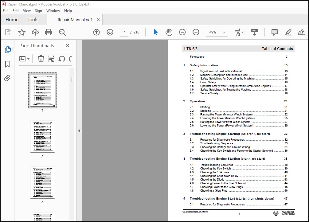
Foreword 3
1 Safety Information 13
1.1 Signal Words Used in this Manual …………………………………………….. 13
1.2 Machine Description and Intended Use ……………………………………… 14
1.3 Safety Guidelines for Operating the Machine ………………………………. 15
1.4 Lamp Safety …………………………………………………………………………… 16
1.5 Operator Safety while Using Internal Combustion Engines …………… 17
1.6 Safety Guidelines for Towing the Machine ………………………………….. 18
1.7 Service Safety ………………………………………………………………………… 19
2 Operation 21
2.1 Starting ………………………………………………………………………………….. 21
2.2 Stopping ………………………………………………………………………………… 21
2.3 Raising the Tower (Manual Winch System) ………………………………… 22
2.4 Lowering the Tower (Manual Winch System) ………………………………. 25
2.5 Raising the Tower (Power Winch System) ………………………………….. 27
2.6 Lowering the Tower (Power Winch System) ……………………………….. 30
3 Troubleshooting Engine Starting (no crank, no start) 32
3.1 Preparing for Diagnostic Procedures …………………………………………. 32
3.2 Troubleshooting Sequence ………………………………………………………. 33
3.3 Checking the Battery and Ground Wiring ……………………………………. 34
3.4 Checking the Key Switch and Power to the Starter Solenoid …………. 36
4 Troubleshooting Engine Starting (crank, no start) 38
4.1 Troubleshooting Sequence ………………………………………………………. 38
4.2 Checking the Key Switch ………………………………………………………….. 39
4.3 Checking the 15A Fuse ……………………………………………………………. 40
4.4 Checking the Shut-down Relay …………………………………………………. 41
4.5 Checking the Diode …………………………………………………………………. 43
4.6 Checking Power to the Fuel Solenoid ………………………………………… 44
4.7 Checking Power to the Glow Plugs ……………………………………………. 45
4.8 Checking a Glow Plug ……………………………………………………………… 46
5 Troubleshooting Engine Start (starts, then shuts down) 47
5.1 Preparing for Diagnostic Procedures …………………………………………. 47
Table of Contents LTN 6/8
8
5.2 Troubleshooting Sequence ………………………………………………………..47
5.3 Checking the Oil Switch …………………………………………………………….48
5.4 Checking the Temperature Switch ………………………………………………50
6 Troubleshooting Engine Starting (no crank, no start) 52
6.1 Preparing for Diagnostic Procedures …………………………………………..52
6.2 Troubleshooting Sequence ………………………………………………………..52
6.3 Checking the Battery and Ground Wiring ……………………………………..53
6.4 Checking Power to the Starter Solenoid and to the Controller …………55
7 Troubleshooting Engine Starting (crank, no start) 57
7.1 Preparing for Diagnostic Procedures …………………………………………..57
7.2 Troubleshooting Sequence ………………………………………………………..57
7.3 Checking the 15A Fuse ……………………………………………………………..58
7.4 Checking Power to the Fuel Solenoid ………………………………………….59
7.5 Checking Power to the Glow Plugs ……………………………………………..61
7.6 Checking a Glow Plug ……………………………………………………………….62
8 Kohler Engine Shut-down Conditions 63
8.1 List of Kohler Engine Shut-down Conditions …………………………………63
8.2 Diagnosing the Oil Pressure Circuit …………………………………………….64
8.3 Checking the Temperature (Dual Function) Switch ………………………..66
8.4 Clearing a Recharging System Fault ……………………………………………69
8.5 Checking the Air Restriction Indicator Switch ………………………………..70
9 Troubleshooting Engine Starting (no crank, no start) 72
9.1 Preparing for Diagnostic Procedures …………………………………………..72
9.2 Troubleshooting Sequence ………………………………………………………..72
9.3 Checking the Battery and Ground Wiring ……………………………………..73
9.4 Checking the Key Switch and Power to the Starter Solenoid …………..75
10 Troubleshooting Engine Starting (crank, no start) 77
10.1 Preparing for Diagnostic Procedures …………………………………………..77
10.2 Troubleshooting Sequence ………………………………………………………..78
10.3 Checking the 15A Fuse ……………………………………………………………..79
10.4 Checking Power to the Fuel Solenoid ………………………………………….80
10.5 Checking the Shut-down Timer Relay ………………………………………….81
LTN 6/8 Table of Contents
wc_br5200013253_01_FM10T 9
10.6 Checking the Temperature Switch …………………………………………….. 83
10.7 Checking a Glow Plug ……………………………………………………………… 84
10.8 Checking the Oil Pressure Switch ……………………………………………… 85
11 Troubleshooting the Lights 86
11.1 Preparing for Diagnostic Procedures …………………………………………. 86
11.2 Determining Where to Start ………………………………………………………. 87
11.3 Checking Engine RPM …………………………………………………………….. 88
11.4 Checking Voltage at the Main Terminal Strip ………………………………. 89
11.5 Checking the Circuit Breakers …………………………………………………… 91
11.6 Checking Power to the Ballast Terminal Strip(s) ………………………….. 93
11.7 Checking a Ballast Transformer ………………………………………………… 95
11.8 Checking a Ballast Capacitor ……………………………………………………. 97
11.9 Checking the Wiring to the Light Fixture(s) …………………………………. 99
11.10 Checking a Light Fixture …………………………………………………………. 102
11.11 Restoring Rotor Magnetism (Flashing) / Checking Rotor Winding … 104
11.12 Checking the Excitation Capacitor …………………………………………… 106
11.13 Checking the Stator Windings …………………………………………………. 107
11.14 Removing the Stator ………………………………………………………………. 109
11.15 Checking the Diodes (older) ……………………………………………………. 111
11.16 Replacing a Diode (older) ……………………………………………………….. 112
11.17 Checking the Diodes (newer) ………………………………………………….. 113
11.18 Replacing a Diode (newer) ……………………………………………………… 114
11.19 Checking the Rotor Windings ………………………………………………….. 115
12 Troubleshooting the Power Winch 116
12.1 Troubleshooting the Power Winch …………………………………………… 116
12.2 Replacing the Cable and Power Winch …………………………………….. 119
13 Disassembly and Reassembly 121
13.1 Tools Required for Disassembly/Assembly Procedures ………………. 121
13.2 Information Regarding Replacement Parts ……………………………….. 121
13.3 Information Regarding Threadlocking Compounds …………………….. 121
13.4 Removing the Radiator—CAT …………………………………………………. 122
13.5 Installing the Radiator—CAT …………………………………………………… 125
13.6 Removing the Radiator—Kohler ………………………………………………. 127
13.7 Removing the Radiator—Kubota ……………………………………………… 129
13.8 Installing the Radiator—Kubota ……………………………………………….. 131
13.9 Removing the Fuel Tank ………………………………………………………… 132
Table of Contents LTN 6/8
10
13.10 Installing the Fuel Tank ……………………………………………………………133
13.11 Removing the Stator ………………………………………………………………..134
13.12 Installing the Stator ………………………………………………………………….136
13.13 Replacing a Diode (older) …………………………………………………………138
13.14 Replacing a Diode (newer) ……………………………………………………….139
13.15 Removing the Doors and the Spine …………………………………………..140
13.16 Installing the Doors and the Spine …………………………………………….142
13.17 Removing the Engine—CAT …………………………………………………….144
13.18 Installing the Engine—CAT ………………………………………………………145
13.19 Removing the Engine—Kohler ………………………………………………….146
13.20 Installing the Engine—Kohler ……………………………………………………147
13.21 Removing the Rotor ………………………………………………………………..148
13.22 Installing the Rotor ………………………………………………………………….149
13.23 Removing the Flex Plates and the Fan ………………………………………150
13.24 Installing the Flex Plates and the Fan ………………………………………..151
13.25 Removing the Tilt Cable …………………………………………………………..152
13.26 Installing the Tilt Cable …………………………………………………………….153
13.27 Removing the Upper Cable ………………………………………………………154
13.28 Installing the Upper Cable ………………………………………………………..156
13.29 Removing the Middle Cable ……………………………………………………..159
13.30 Installing the Middle Cable ……………………………………………………….162
13.31 Removing a Ballast Transformer ……………………………………………….166
13.32 Installing a Ballast Transformer …………………………………………………167
14 Technical Data—LTN6C 168
14.1 Engine …………………………………………………………………………………..168
14.2 Generator ………………………………………………………………………………169
14.3 Machine …………………………………………………………………………………169
14.4 Radiation Compliance ……………………………………………………………..170
15 Technical Data—LTN 6L 171
15.1 Engine …………………………………………………………………………………..171
15.2 Generator ………………………………………………………………………………172
15.3 Machine …………………………………………………………………………………173
15.4 Radiation Compliance ……………………………………………………………..174
16 Technical Data—LTN 6/8K 176
16.1 Engine …………………………………………………………………………………..176
16.2 Generator ………………………………………………………………………………177
LTN 6/8 Table of Contents
wc_br5200013253_01_FM10T 11
16.3 Machine ……………………………………………………………………………….. 177
16.4 Radiation Compliance ……………………………………………………………. 178
17 Schematics—LTN 6C 180
17.1 Lighting Schematic—120V ……………………………………………………… 180
17.2 Components …………………………………………………………………………. 181
17.3 Lighting Schematic—120/240V ……………………………………………….. 182
17.4 Components …………………………………………………………………………. 183
17.5 Generator Capacitor Excitation Schematic ……………………………….. 184
17.6 Generator Capacitor Excitation Schematic ……………………………….. 185
17.7 Engine Wiring ……………………………………………………………………….. 186
17.8 Components …………………………………………………………………………. 187
17.9 Power Winch Schematic ………………………………………………………… 187
17.10 Trailer Wiring ………………………………………………………………………… 188
18 Schematics—LTN 6L 190
18.1 Lighting Schematic—120V ……………………………………………………… 190
18.2 Components—120V ………………………………………………………………. 191
18.3 Lighting Schematic—120V/240V ……………………………………………… 192
18.4 Components—120V/240V ………………………………………………………. 193
18.5 Engine Wiring Rev > 133 ………………………………………………………… 194
18.6 Components Rev > 133 ………………………………………………………….. 195
18.7 Control Panel Wiring Rev > 133 ………………………………………………. 196
18.8 Components Rev > 133 ………………………………………………………….. 197
18.9 Engine Wiring Rev < 134 ………………………………………………………… 198
18.10 Components Rev < 134 ………………………………………………………….. 199
18.11 Control Panel Wiring Rev < 134 ………………………………………………. 200
18.12 Components Rev < 134 ………………………………………………………….. 200
18.13 Power Winch Schematic ………………………………………………………… 201
18.14 Generator Capacitor Excitation Schematic—120V …………………….. 202
18.15 Generator Capacitor Excitation Schematic—120V/240V …………….. 203
18.16 Trailer Wiring ………………………………………………………………………… 204
19 Schematics—LTN 6K / LTN 8K 206
19.1 Lighting Schematic—LTN 6K ………………………………………………….. 206
19.2 Components—LTN 6K …………………………………………………………… 207
19.3 Lighting Schematic—LTN 8K ………………………………………………….. 208
19.4 Components—LTN 8K …………………………………………………………… 209
19.5 Engine Wiring ……………………………………………………………………….. 210
Table of Contents LTN 6/8
12
19.6 Components …………………………………………………………………………..211
19.7 Power Winch Schematic ………………………………………………………….212
19.8 Generator Capacitor Excitation Schematic …………………………………213
19.9 Trailer Wiring ………………………………………………………………………….214
VIDEO PREVIEW OF THE MANUAL:
PLEASE NOTE:
- This is the SAME exact manual used by your dealers to fix your vehicle.
- The same can be yours in the next 2-3 mins as you will be directed to the download page immediately after paying for the manual.
- Any queries / doubts regarding your purchase, please feel free to contact [email protected]
S.V


