

Wacker Neuson EZ28 EZ36 Track excavator Service manual – PDF DOWNLOAD
IMAGES PREVIEW OF THE MANUAL:

DESCRIPTION:
Wacker Neuson EZ28 EZ36 Track excavator Service manual – PDF DOWNLOAD
1 Operation
1.1 Information on this service manual
- This service manual contains important information on how to work safely, correctly, and economically with the machine. Therefore, it aims not only at new personnel, but it also serves as a reference for experienced personnel.
- It helps to avoid hazardous situations and reduce repair costs and downtimes. Furthermore, the reliability and the service life of the machine will be increased by following the instructions in the Operator’s Manual. Careful and prudent working is the best way to avoid accidents! Operational safety and readiness of the machine do not only depend on your skill, but also
- on maintenance and servicing of the machine. This is why regular maintenance and servicing is absolutely necessary. Extensive maintenance and repair work must always be performed by a Wacker Neuson service center. Use only original spare parts for repairs. This ensures operational safety and readiness of your machine, and maintains its value.
TABLE OF CONTENTS:
Wacker Neuson EZ28 EZ36 Track excavator Service manual – PDF DOWNLOAD
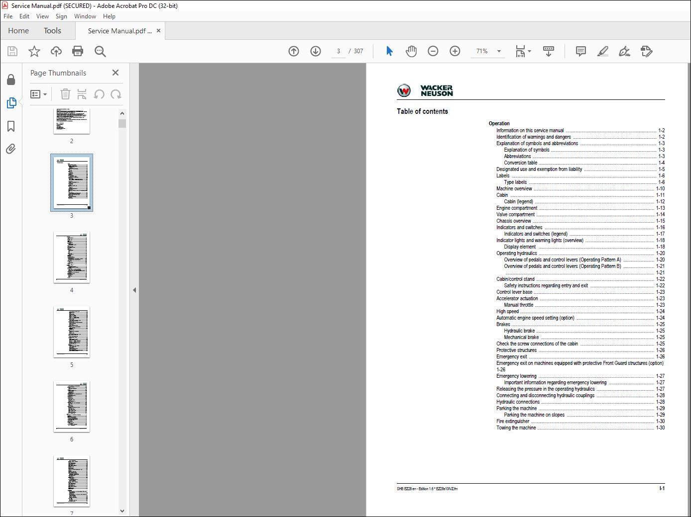
Operation
Information on this service manual ……………………………………………………………….. 1-2
Identification of warnings and dangers ………………………………………………………….. 1-2
Explanation of symbols and abbreviations …………………………………………………….. 1-3
Explanation of symbols ………………………………………………………………………….. 1-3
Abbreviations ……………………………………………………………………………………….. 1-3
Conversion table …………………………………………………………………………………… 1-4
Designated use and exemption from liability ………………………………………………….. 1-5
Labels ………………………………………………………………………………………………………. 1-6
Type labels ………………………………………………………………………………………….. 1-6
Machine overview …………………………………………………………………………………….. 1-10
Cabin ……………………………………………………………………………………………………… 1-11
Cabin (legend) ……………………………………………………………………………………. 1-12
Engine compartment …………………………………………………………………………………. 1-13
Valve compartment …………………………………………………………………………………… 1-14
Chassis overview ……………………………………………………………………………………… 1-15
Indicators and switches …………………………………………………………………………….. 1-16
Indicators and switches (legend) …………………………………………………………… 1-17
Indicator lights and warning lights (overview) ……………………………………………….. 1-18
Display element …………………………………………………………………………………. 1-18
Operating hydraulics …………………………………………………………………………………. 1-20
Overview of pedals and control levers (Operating Pattern A) ……………………. 1-20
Overview of pedals and control levers (Operating Pattern B) ……………………. 1-21
…………………………………………………………………………………………………………. 1-21
Cabin/control stand …………………………………………………………………………………… 1-22
Safety instructions regarding entry and exit ……………………………………………. 1-22
Control lever base …………………………………………………………………………………….. 1-23
Accelerator actuation ………………………………………………………………………………… 1-23
Manual throttle ……………………………………………………………………………………. 1-23
High speed ………………………………………………………………………………………………. 1-24
Automatic engine speed setting (option) ……………………………………………………… 1-24
Brakes …………………………………………………………………………………………………….. 1-25
Hydraulic brake …………………………………………………………………………………… 1-25
Mechanical brake ……………………………………………………………………………….. 1-25
Check the screw connections of the cabin …………………………………………………… 1-25
Protective structures …………………………………………………………………………………. 1-26
Emergency exit ………………………………………………………………………………………… 1-26
Emergency exit on machines equipped with protective Front Guard structures (option)
1-26
Emergency lowering …………………………………………………………………………………. 1-27
Important information regarding emergency lowering ………………………………. 1-27
Releasing the pressure in the operating hydraulics ……………………………………….. 1-27
Connecting and disconnecting hydraulic couplings ……………………………………….. 1-28
Hydraulic connections ……………………………………………………………………………….. 1-28
Parking the machine …………………………………………………………………………………. 1-29
Parking the machine on slopes …………………………………………………………….. 1-29
Fire extinguisher ………………………………………………………………………………………. 1-30
Towing the machine ………………………………………………………………………………….. 1-30
I-2 SHB EZ28 en – Edition 1.6 * EZ28s10IVZ.fm
Technical data
Models and trade names …………………………………………………………………………….. 2-2
Engine ………………………………………………………………………………………………………. 2-2
Traveling drive/axles …………………………………………………………………………………… 2-4
Tracks ………………………………………………………………………………………………………. 2-4
Fuel injection pump …………………………………………………………………………………….. 2-4
Brakes ………………………………………………………………………………………………………. 2-4
Steering system …………………………………………………………………………………………. 2-4
Hose identification code ………………………………………………………………………………. 2-4
Hydraulic system ………………………………………………………………………………………… 2-5
Operating hydraulics ……………………………………………………………………………… 2-5
Auxiliary hydraulics flow rate EZ28 ………………………………………………………….. 2-5
Speed ……………………………………………………………………………………………………….. 2-6
Coolant compound table ……………………………………………………………………………… 2-6
Ground clearance/ground pressure ………………………………………………………………. 2-6
Excavator forces ………………………………………………………………………………………… 2-6
Vibration ……………………………………………………………………………………………………. 2-6
Electrical system ………………………………………………………………………………………… 2-7
Electrical components ……………………………………………………………………………. 2-7
Fuses ………………………………………………………………………………………………….. 2-7
Relays …………………………………………………………………………………………………. 2-7
Bulbs …………………………………………………………………………………………………… 2-7
Weight ………………………………………………………………………………………………………. 2-8
Machine weight …………………………………………………………………………………….. 2-8
Weight of attachments …………………………………………………………………………… 2-8
Noise emissions …………………………………………………………………………………………. 2-8
Powertilt (option) ………………………………………………………………………………………… 2-9
Engine tightening torques ……………………………………………………………………………. 2-9
Model-specific tightening torques …………………………………………………………………. 2-9
General tightening torques …………………………………………………………………………. 2-10
Tightening torques for hydraulic threaded fittings (dry assembly) ………………. 2-10
Tightening torques for high-resistance threaded fittings ……………………………. 2-12
Payload/lift capacity ………………………………………………………………………………….. 2-12
Dimensions ……………………………………………………………………………………………… 2-13
Overview EZ28 …………………………………………………………………………………… 2-13
Overview EZ28 VDS ……………………………………………………………………………. 2-15
Kinematics ………………………………………………………………………………………………. 2-17
Measuring live ring tolerance ……………………………………………………………………… 2-18
Maintenance
Information on maintenance ………………………………………………………………………… 3-2
Responsibilities and prerequisites …………………………………………………………… 3-2
Important safety instructions on maintenance …………………………………………… 3-2
Service package ………………………………………………………………………………………… 3-2
Fluids and lubricants …………………………………………………………………………………… 3-3
Oil types for diesel engine (depending on temperature) ……………………………… 3-4
Oil types for hydraulic system (depending on temperature) ………………………… 3-5
Important information regarding operation with biodegradable hydraulic oil ….. 3-5
Maintenance label ………………………………………………………………………………………. 3-6
Explanation of symbols on the maintenance label ……………………………………… 3-7
Maintenance plan ……………………………………………………………………………………….. 3-8
Overview of maintenance areas …………………………………………………………………. 3-12
Maintenance accesses ……………………………………………………………………………… 3-13
Engine cover ………………………………………………………………………………………. 3-13
Reservoir cover …………………………………………………………………………………… 3-14
Fuse box ……………………………………………………………………………………………. 3-14
Fuel system ……………………………………………………………………………………………… 3-15
SHB EZ28 en – Edition 1.6 * EZ28s10IVZ.fm I-3
Important information regarding the fuel system ……………………………………… 3-15
Diesel fuel specification ……………………………………………………………………….. 3-15
Refueling …………………………………………………………………………………………… 3-15
Emptying the fuel tank …………………………………………………………………………. 3-16
Bleeding the fuel system ……………………………………………………………………… 3-17
Checking the water separator ……………………………………………………………….. 3-17
Emptying the water separator ……………………………………………………………….. 3-18
Fuel filter with water separator ……………………………………………………………… 3-19
Checking the water separator on fuel filter ……………………………………………… 3-19
Emptying the water separator on the fuel filter ………………………………………… 3-20
Replacing the fuel filter ………………………………………………………………………… 3-21
Washer system (option) …………………………………………………………………………….. 3-22
Important information regarding the washer system ………………………………… 3-22
Checking the fluid level and adding fluid ………………………………………………… 3-22
Engine lubrication system ………………………………………………………………………….. 3-23
Important information regarding the engine lubrication system ………………….. 3-23
Checking the engine oil level ………………………………………………………………… 3-23
Adding engine oil ………………………………………………………………………………… 3-23
Changing engine oil …………………………………………………………………………….. 3-24
Replacing the engine-oil filter cartridge ………………………………………………….. 3-25
Cooling system ………………………………………………………………………………………… 3-27
Important information regarding the cooling system …………………………………. 3-27
Checking the coolant level ……………………………………………………………………. 3-27
Adding coolant ……………………………………………………………………………………. 3-28
Draining coolant ………………………………………………………………………………….. 3-29
Cleaning the radiator …………………………………………………………………………… 3-31
Air filter ……………………………………………………………………………………………………. 3-32
Important information regarding the air filter ……………………………………………. 3-32
Dirt indicator ………………………………………………………………………………………. 3-33
Replacing the air filter ………………………………………………………………………….. 3-33
Checking the air intake ………………………………………………………………………… 3-34
Heating, ventilation and air conditioning system (option) ……………………………….. 3-35
Checking/replacing the fresh-air filter …………………………………………………….. 3-35
V-belt ……………………………………………………………………………………………………… 3-36
Checking V-belt condition and tension …………………………………………………… 3-36
Replacing/retensioning the V-belt ………………………………………………………….. 3-37
Pressure check ………………………………………………………………………………………… 3-40
General ……………………………………………………………………………………………… 3-40
Measurement connections (overview) ……………………………………………………. 3-40
Checking pilot control pressure …………………………………………………………….. 3-40
Pressure check of variable displacement pump P1 ………………………………….. 3-41
Pressure check of variable displacement pump P2 ………………………………….. 3-42
Pressure check of gear pump P3 ………………………………………………………….. 3-43
Secondary pressure limiting valve for swivel unit …………………………………….. 3-43
Primary pressure limiting valves ……………………………………………………………. 3-44
Test report ………………………………………………………………………………………………. 3-45
Hydraulic system ……………………………………………………………………………………… 3-49
Important information on the hydraulic system ………………………………………… 3-49
Checking the hydraulic oil level …………………………………………………………….. 3-50
Adding hydraulic oil …………………………………………………………………………….. 3-50
Changing hydraulic oil …………………………………………………………………………. 3-51
Monitoring the hydraulic oil return filter …………………………………………………… 3-51
Replacing the hydraulic oil filter …………………………………………………………….. 3-52
Draining condensation water from the hydraulic oil reservoir …………………….. 3-52
Checking the hydraulic system for leaks ………………………………………………… 3-53
I-4 SHB EZ28 en – Edition 1.6 * EZ28s10IVZ.fm
Checking the condition and age of hydraulic hoses …………………………………. 3-53
Checking the pilot control filter ……………………………………………………………………. 3-54
Traveling drive …………………………………………………………………………………………. 3-55
Checking the oil level and adding oil ……………………………………………………… 3-55
Draining oil …………………………………………………………………………………………. 3-55
Tires/tracks ……………………………………………………………………………………………… 3-56
Important information on the tracks ……………………………………………………….. 3-56
Checking track tension ………………………………………………………………………… 3-56
Correcting track tension ……………………………………………………………………….. 3-57
Replacing the tracks ……………………………………………………………………………. 3-58
Maintenance of attachments ………………………………………………………………………. 3-58
Important information regarding maintenance of attachments …………………… 3-58
Maintenance of options ……………………………………………………………………………… 3-59
Joint rod (lifting eye) and load hook ……………………………………………………….. 3-59
Lubrication work ……………………………………………………………………………………….. 3-59
Preparing lubrication ……………………………………………………………………………. 3-59
Lubrication schedule …………………………………………………………………………………. 3-60
Live ring (ball bearing) …………………………………………………………………………. 3-62
Live ring gears ……………………………………………………………………………………. 3-63
Live ring gear VDS (option) ………………………………………………………………….. 3-64
Control lever base ……………………………………………………………………………….. 3-65
Using the quickhitches in water …………………………………………………………….. 3-65
Electrical system ………………………………………………………………………………………. 3-66
Important information regarding the electrical system ………………………………. 3-66
Fuses and relays ………………………………………………………………………………… 3-66
Battery ………………………………………………………………………………………………. 3-67
Charging the battery ……………………………………………………………………………. 3-67
Replacing the battery …………………………………………………………………………… 3-67
Cleaning and maintenance ………………………………………………………………………… 3-68
Important information on cleaning and maintenance ………………………………… 3-68
Use of solvents …………………………………………………………………………………… 3-69
Cleaning inside the cabin ……………………………………………………………………… 3-69
Cleaning outside the machine ………………………………………………………………. 3-69
Cleaning the engine compartment …………………………………………………………. 3-69
Cleaning the seat belt ………………………………………………………………………….. 3-70
Cleaning the shatter protection ……………………………………………………………… 3-70
Threaded fittings and attachments ………………………………………………………… 3-70
Resetting the maintenance meter ……………………………………………………………….. 3-70
Engine
Overview of engine 3TNV76-NNS (Tier IV final up to 2012) ……………………………… 4-2
Fuel system ……………………………………………………………………………………………….. 4-4
Cooling system ………………………………………………………………………………………….. 4-5
Checking and adjusting valve clearance ………………………………………………………… 4-6
Tightening order for cylinder head bolts …………………………………………………………. 4-7
Order for removing the cylinder-head bolts: ……………………………………………… 4-7
Order for installing the cylinder-head bolts: ………………………………………………. 4-7
Checking the injection nozzles ……………………………………………………………………… 4-8
Pressure check …………………………………………………………………………………….. 4-8
Checking the nozzle jet ……………………………………………………………………………….. 4-8
Injection time ……………………………………………………………………………………………… 4-9
Checking injection time ………………………………………………………………………….. 4-9
Setting injection time ……………………………………………………………………………. 4-11
Removing and installing the injection pump ………………………………………………….. 4-11
Removing the injection pump ……………………………………………………………….. 4-11
SHB EZ28 en – Edition 1.6 * EZ28s10IVZ.fm I-5
Fitting the fuel injection pump ……………………………………………………………….. 4-12
Measuring and adjusting the engine speed ………………………………………………….. 4-13
Compression ……………………………………………………………………………………………. 4-14
Checking the coolant thermostat ………………………………………………………………… 4-14
Checking the temperature sensor ……………………………………………………………….. 4-15
Oil pressure switch …………………………………………………………………………………… 4-15
Checking the coolant circuit ……………………………………………………………………….. 4-15
Cleaning the cooling water channels …………………………………………………………… 4-15
Coolant and fuel hoses ……………………………………………………………………………… 4-16
Crankcase vent ………………………………………………………………………………………… 4-16
Replacing the glow plugs …………………………………………………………………………… 4-16
Engine malfunctions …………………………………………………………………………………. 4-17
Overview of engine 3TNV80F-SNNS (Tier IV final from 2012) ………………………… 4-19
Fuel system …………………………………………………………………………………………….. 4-21
Cooling system ………………………………………………………………………………………… 4-22
Altitude-dependent output reduction ……………………………………………………………. 4-23
Checking and adjusting valve clearance ……………………………………………………… 4-24
Tightening order for cylinder head bolts ………………………………………………………. 4-26
Order for removing the cylinder-head bolts: ……………………………………………. 4-26
Order for installing the cylinder-head bolts: …………………………………………….. 4-26
Checking the injection nozzles …………………………………………………………………… 4-27
Pressure check …………………………………………………………………………………… 4-27
Checking the nozzle jet ……………………………………………………………………………… 4-28
Injection time ……………………………………………………………………………………………. 4-28
Checking injection time ………………………………………………………………………… 4-28
Setting injection time …………………………………………………………………………… 4-30
Removing and installing the injection pump …………………………………………………. 4-31
Removing the injection pump ……………………………………………………………….. 4-31
Fitting the fuel injection pump ……………………………………………………………….. 4-32
Measuring and adjusting the engine speed ………………………………………………….. 4-34
Compression ……………………………………………………………………………………………. 4-34
Checking the coolant thermostat ………………………………………………………………… 4-35
Checking the temperature sensor ……………………………………………………………….. 4-35
Oil pressure switch …………………………………………………………………………………… 4-36
Checking the coolant circuit ……………………………………………………………………….. 4-36
Cleaning the cooling water channels …………………………………………………………… 4-36
Coolant and fuel hoses ……………………………………………………………………………… 4-37
Crankcase vent ………………………………………………………………………………………… 4-37
Replacing the glow plugs …………………………………………………………………………… 4-37
Engine malfunctions …………………………………………………………………………………. 4-38
Hydraulic system
Hydraulic pump ………………………………………………………………………………………….. 5-3
Double variable displacement und twin gear pump PVD-0B-23BP-8G3-5083A
(Yanmar 3TNV76-NNS) …………………………………………………………………………. 5-3
Pump unit: exploded view ………………………………………………………………………. 5-5
Pilot oil supply unit ………………………………………………………………………………… 5-6
Double variable displacement und twin gear pump PVD-0B-23BCP-8G3-5498Z
(Yanmar 3TNV80F-SNNS) …………………………………………………………………….. 5-7
Dismantling the hydraulic pump ……………………………………………………………… 5-9
Assembling the hydraulic pump …………………………………………………………….. 5-11
Malfunctions of the hydraulic pump ……………………………………………………….. 5-15
Main valve block ………………………………………………………………………………………. 5-16
Connections ……………………………………………………………………………………….. 5-16
Main control lines ………………………………………………………………………………… 5-20
Pressure limiting and other valves …………………………………………………………. 5-21
Drive counterbalancing system …………………………………………………………………… 5-22
I-6 SHB EZ28 en – Edition 1.6 * EZ28s10IVZ.fm
Pump assignment for drive counterbalancing ………………………………………….. 5-22
Regeneration – stick segment ……………………………………………………………………. 5-23
Bucket pre-tension ……………………………………………………………………………………. 5-23
Traveling drive …………………………………………………………………………………………. 5-24
Function …………………………………………………………………………………………….. 5-25
Swivel unit ……………………………………………………………………………………………….. 5-27
Swivel unit brake …………………………………………………………………………………. 5-28
Swivel joint ………………………………………………………………………………………………. 5-30
Swivel joint VDS (option) …………………………………………………………………………… 5-31
Pilot valves ………………………………………………………………………………………………. 5-32
Joystick ……………………………………………………………………………………………… 5-32
Pilot valve (machine travel) …………………………………………………………………… 5-33
Valves …………………………………………………………………………………………………….. 5-34
Proportional valve (option) ……………………………………………………………………. 5-34
Changeover valve VDS (option) ……………………………………………………………. 5-34
3/2 directional valve (option) …………………………………………………………………. 5-34
8/2 directional valve (option) …………………………………………………………………. 5-35
Hydraulic quickhitch valve (option) ………………………………………………………… 5-35
Hydraulic oil reservoir service valve ………………………………………………………. 5-35
Breather filter …………………………………………………………………………………………… 5-36
Malfunctions of the hydraulic system …………………………………………………………… 5-36
Electrical system
Ohm’s Law (current, voltage, resistance); power …………………………………………….. 6-2
Measuring equipment, measuring methods ……………………………………………………. 6-2
Relays ………………………………………………………………………………………………………. 6-3
Use, mode of function ……………………………………………………………………………. 6-3
Electric units ………………………………………………………………………………………………. 6-4
Fuses/relays ………………………………………………………………………………………………. 6-4
Fuses ………………………………………………………………………………………………….. 6-4
Relays …………………………………………………………………………………………………. 6-4
Bulbs ………………………………………………………………………………………………………… 6-4
Alternator ………………………………………………………………………………………………….. 6-5
Starter ………………………………………………………………………………………………………. 6-5
12 V power outlet ……………………………………………………………………………………….. 6-5
Socket ………………………………………………………………………………………………………. 6-6
Radio (option) ……………………………………………………………………………………………. 6-6
Rotating beacon (option) ……………………………………………………………………………… 6-6
Engine/chassis wiring harness legend (Yanmar – Tier IV final up to 2012) …………. 6-8
Engine/chassis wiring harness (Yanmar – Tier IV final up to 2012) …………………. 6-10
Engine/chassis wiring harness legend (Yanmar – Tier IV final from 2012) (up to serial
no. WNCE1002PPAL00526) ………………………………………………………………………. 6-11
Engine/chassis wiring harness (Yanmar – Tier IV final from 2012) (up to serial no.
WNCE1002PPAL00526) ……………………………………………………………………………. 6-14
Engine/chassis wiring harness legend (Yanmar – TIER IV final from 2012) ……… 6-15
Engine/chassis wiring harness (Yanmar – TIER IV final from 2012) ………………… 6-18
Engine/chassis wiring harness legend (Yanmar – TIER IV final from 2012) ……… 6-19
Engine/chassis wiring harness (Yanmar – TIER IV final from 2012) ………………… 6-22
Cabin wiring harness ………………………………………………………………………………… 6-23
Canopy lights wiring harness (option) ………………………………………………………….. 6-24
Proportional controls wiring harness (option) ………………………………………………… 6-25
Engine speed control wiring harness (option) ……………………………………………….. 6-26
Travel signal wiring harness (option) …………………………………………………………… 6-27
Hydraulic quickhitch wiring harness (option) …………………………………………………. 6-28
Battery lead ……………………………………………………………………………………………… 6-29
SHB EZ28 en – Edition 1.6 * EZ28s10IVZ.fm I-7
Diagrams
Hydraulics diagram (legend) ………………………………………………………………………… 7-2
Hydraulics diagram (up to serial no. WNCE1002LPAL00499) ………………………….. 7-3
3rd control circuit hydraulics diagram (up to serial no. WNCE1002LPAL00499) …. 7-4
Options hydraulics diagram (up to serial no. WNCE1002LPAL00499) ………………. 7-5
Hydraulics diagram (from serial no. WNCE1002JPAL00500) …………………………… 7-6
3rd control circuit hydraulics diagram (from serial no. WNCE1002JPAL00500) ….. 7-7
Hydraulics diagram – options version 1 …………………………………………………………. 7-8
Hydraulics diagram – options version 2 …………………………………………………………. 7-9
Wiring diagram legend (up to serial no. WNCE1002PPAL00526) ……………………. 7-10
Wiring diagram (up to serial no. WNCE1002PPAL00526) ……………………………… 7-11
Wiring diagram legend (from serial no. WNCE1002KPAL00527) ……………………. 7-12
Wiring diagram (from serial no. WNCE1002KPAL00527) ………………………………. 7-13
Options
Counterweight ……………………………………………………………………………………………. 8-2
Technical data ……………………………………………………………………………………… 8-2
Long stick ………………………………………………………………………………………………….. 8-2
Technical data ……………………………………………………………………………………… 8-2
Automatic engine speed setting ……………………………………………………………………. 8-3
Grab control circuit ……………………………………………………………………………………… 8-4
Setting grab operation …………………………………………………………………………… 8-4
Stopping bucket operation ……………………………………………………………………… 8-4
Attachments ………………………………………………………………………………………………. 8-4
Safe load indicator ……………………………………………………………………………………… 8-5
Setting the pressure switch ……………………………………………………………………. 8-7
Hose burst valve ………………………………………………………………………………………… 8-8
Hydraulic quickhitch valve …………………………………………………………………………… 8-9
Hydraulic quickhitch pressure variants …………………………………………………… 8-10
Easy Lock emergency unlocking (hydraulic quickhitch from serial no. 2200) . 8-12
Tilting the upper carriage (Vertical Digging System) ……………………………………… 8-13
3rd control circuit ……………………………………………………………………………………… 8-14
Diagram …………………………………………………………………………………………….. 8-14
Proportional controls …………………………………………………………………………………. 8-15
Hammer operation ……………………………………………………………………………………. 8-16
Important information regarding hammer operation …………………………………. 8-16
Additional control circuit – AUX I ………………………………………………………………… 8-17
Proportionally controlled additional control circuit – AUX I ……………………………… 8-17
Swiveling the boom …………………………………………………………………………………… 8-18
Swiveling the boom (proportionally controlled) ……………………………………………… 8-18
Powertilt – AUX II ……………………………………………………………………………………… 8-19
ISO/SAE controls ……………………………………………………………………………………… 8-20
Travel signal ……………………………………………………………………………………………. 8-21
Immobilizer ……………………………………………………………………………………………… 8-21
Engine oil service valve …………………………………………………………………………….. 8-22
Function …………………………………………………………………………………………….. 8-22
Telematic ………………………………………………………………………………………………… 8-23
Connections ……………………………………………………………………………………….. 8-23
Functional check/diode ………………………………………………………………………… 8-23
PowerTilt PTS06
General instructions ……………………………………………………………………………………. 9-2
General safety instructions …………………………………………………………………….. 9-2
Checking the product …………………………………………………………………………….. 9-3
Internal decompression valve …………………………………………………………………. 9-3
Testing the hydraulic system of the machine ……………………………………………. 9-3
Specifications/requirements …………………………………………………………………… 9-4
Tools ………………………………………………………………………………………………………… 9-5
I-8 SHB EZ28 en – Edition 1.6 * EZ28s10IVZ.fm
Making a tool VI for removing the seals ……………………………………………………. 9-6
Separating the bucket or equipment from the PowerTilt swivel device ……………….. 9-6
Separating the PowerTilt swivel device from the machine ………………………………… 9-6
Exploded views PTS06 ……………………………………………………………………………….. 9-7
PTS06 components ………………………………………………………………………………. 9-7
Sealing kit A and bearing kit B PTS06 (overview) ……………………………………… 9-8
Assembly drawing ………………………………………………………………………………………. 9-9
Removing the standard journal coupling ………………………………………………………. 9-10
Removing the end cap, circlip and internal decompression valve ……………………. 9-12
Removing the shaft …………………………………………………………………………………… 9-13
Removing the piston tube body ………………………………………………………………….. 9-14
Removing the seals (kit A), shaft bearings and pressure disks (kit B) ………………. 9-15
Checking components and dead center marks ……………………………………………… 9-16
Trial assembly ………………………………………………………………………………………….. 9-17
Installing the seals (kit A), shaft bearings and pressure disks (kit B) ………………… 9-17
Installing the end-cap seals and bearings ………………………………………………. 9-17
Installing the piston seals and bearings ………………………………………………….. 9-18
Fitting the shaft seal and the bearing ……………………………………………………… 9-19
Installing the piston tube ……………………………………………………………………………. 9-20
Installing the shaft …………………………………………………………………………………….. 9-21
Installing the end cap and the circlip ……………………………………………………………. 9-22
Installing the internal decompression valve ………………………………………………….. 9-23
Installing the standard journal coupling ………………………………………………………… 9-23
Lubrication and tests …………………………………………………………………………………. 9-27
Lubrication …………………………………………………………………………………………. 9-27
Test for internal leaks ………………………………………………………………………….. 9-27
Testing the internal decompression valve ………………………………………………. 9-28
Securing the PowerTilt swivel device on the machine ……………………………………. 9-29
Fitting a bucket or equipment onto the PowerTilt swivel device ………………………. 9-29
Adjusting the play on the PowerTilt ……………………………………………………………… 9-30
Checking the circumferential play ………………………………………………………….. 9-30
Troubleshooting ………………………………………………………………………
VIDEO PREVIEW OF THE MANUAL:
PLEASE NOTE:
- This is the SAME exact manual used by your dealers to fix your vehicle.
- The same can be yours in the next 2-3 mins as you will be directed to the download page immediately after paying for the manual.
- Any queries / doubts regarding your purchase, please feel free to contact [email protected]
S.M


