Wacker Neuson 9503 Mobile Excavator Service Manual 1000175340 PDF
$36.95
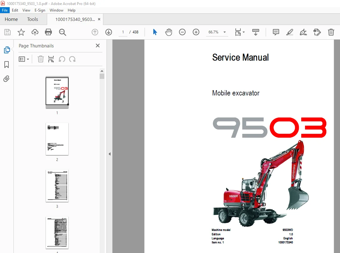
Wacker Neuson 9503 Mobile Excavator Service Manual 1000175340 – PDF DOWNLOAD
Description
Wacker Neuson 9503 Mobile Excavator Service Manual 1000175340 – PDF DOWNLOAD
FILE DETAILS:
Wacker Neuson 9503 Mobile Excavator Service Manual 1000175340 – PDF DOWNLOAD
Language : English
Pages : 438
Downloadable : Yes
File Type : PDF
IMAGES PREVIEW OF THE MANUAL:
TABLE OF CONTENTS:
Wacker Neuson 9503 Mobile Excavator Service Manual 1000175340 – PDF DOWNLOAD
Important information on this service manual 1-1
Abbreviations/symbols 1-1
Identification of warnings and dangers 1-2
Designated use and exemption from liability 1-3
Type labels and component numbers 1-4
Serial number 1-4
Cab 1-4
Engine 1-4
Hydraulic pump type label 1-5
Main valve block 1-5
Axles 1-5
Swivel unit 1-6
Transfer gearbox 1-6
Hydraulic motor 1-6
Machine overview 1-7
Engine compartment: overview 1-8
Chassis overview 1-9
Tilting the cab 1-10
Heating 1-12
Air conditioning (option) 1-12
Recirculated air mode 1-13
Battery master switch 1-13
Inside of cab: overview 1-15
Specifications
Chassis 2-1
Engine 2-1
Capacities 2-2
Tightening torques 2-2
Undercarriage 2-2
Power train 2-3
Variable displacement pump 2-3
Variable displacement motor 2-3
Transfer gearbox 2-3
Axles 2-4
Front axle 2-4
Rear axle 2-4
Brakes 2-4
Steering system 2-5
Tyres 2-5
Hydraulics 2-6
Auxiliary hydraulics oil flow 2-7
3rd control circuit oil flow 2-7
Swivel unit 2-7
Outriggers or stabiliser blade (option) 2-7
Electric system 2-8
Fuse box 2-8
Main fuse box with relays on partition wall 2-9
Relays 2-9
Noise levels 2-10
Vibration 2-10
Coolant compound table 2-10
Model-specific tightening torques 2-10
General tightening torques 2-11
Table of contents
I-2 SERV-HB 9503 EN – Edition 1 0 * 9503s10IVZ fm
Table of contents
Tightening torques for hydraulic screw connections (dry assembly) 2-11
Tightening torques for high-resistance screw connections 2-13
Kinematics 2-14
Dimensions model 9503 WD 2-15
Dimensions model 9503 WD with triple articulation boom (option) 2-16
Lift capacity table 1: 20/40 kph version, rear stabiliser blade, one steering axle, one-piece
boom, twin tyres 2-17
Lift capacity table 2: 20/40 kph version, rear stabiliser blade, one steering axle, one-piece
boom, wide tyres 2-18
Lift capacity table 3: 20/40 kph version, rear stabiliser blade, front outriggers, one steering
axle, one-piece boom, twin tyres 2-19
Lift capacity table 4: 20/40 kph version, rear stabiliser blade, front outriggers, one steering
axle, one-piece boom, wide tyres 2-20
Lift capacity table 5: 20/40 kph version, rear outriggers, one steering axle, one-piece
boom, twin tyres 2-21
Lift capacity table 6: 20/40 kph version, rear outriggers, one steering axle, one-piece
boom, wide tyres 2-22
Lift capacity table 7: 20/40 kph version, rear stabiliser blade, one steering axle, triple
articulation boom, twin tyres 2-23
Lift capacity table 8: 20/40 kph version, rear stabiliser blade, one steering axle, triple
articulation boom, wide tyres 2-24
Lift capacity table 9: 20/40 kph version, rear stabiliser blade, front outriggers, one steering
axle, triple articulation boom, twin tyres 2-25
Lift capacity table 10: 20/40 kph version, rear stabiliser blade, front outriggers, one steering
axle, triple articulation boom, wide tyres 2-26
Lift capacity table 11: 20/40 kph version, rear outriggers, one steering axle, triple articulation
boom, twin tyres 2-27
Lift capacity table 12: 20/40 kph version, rear outriggers, one steering axle, triple articulation
boom, wide tyres 2-28
Maintenance
Fluids and lubricants 3-1
Additional oil change and filter replacement (hydraulics) 3-2
Maintenance label 3-3
Explanation of symbols on the maintenance label 3-3
Maintenance plan (overview) 3-6
Service package 3-10
Introduction 3-10
Interlocks 3-10
Fuel system 3-11
Specific safety instructions 3-11
Refuelling 3-11
Fuel-filling pump (option) 3-12
Stationary fuel pumps 3-12
Diesel fuel specification 3-12
Bleeding the fuel system 3-13
Emptying the fuel tank 3-13
Cleanind/replacing/bleeding the fuel prefilter 3-14
Replacing the fuel filter 3-15
Engine lubrication system 3-16
Checking the engine oil level 3-16
Filling up engine oil 3-17
Changing engine oil 3-18
Replacing the engine oil filter cartridge 3-19
Engine and hydraulics cooling system 3-20
Specific safety instructions 3-20
Checking/filling up coolant 3-21
SERV-HB 9503 EN – Edition 1 0 * 9503s10IVZ fm I-3
Table of contents
Draining coolant 3-22
Air filter 3-24
Filter replacement 3-25
Daily functional check of the dust valve 3-26
V-belts 3-27
Checking V-belt tension 3-27
Retightening V-belts 3-28
Checking the V-belt of the air conditioning system (option) 3-29
Tightening the V-belt of the air conditioning system (option) 3-29
Gearboxes and axles 3-30
Checking the oil level in the 20 kph rear axle 3-30
Filling up gearbox oil 3-30
Replacing the transfer gearbox 3-30
Changing gearbox oil 3-31
Checking the oil level in the 40 kph rear axle (option) 3-31
Differential oil level (rigid rear axle) 3-32
Draining the oil in the differential (rigid rear axle) 3-32
Differential oil level (steered rear axle) 3-33
Front axle differential oil level 3-34
Draining the oil in the front axle differential 3-34
Checking the oil level on the planetary drive of the rigid rear axle, and filling up oil
3-35
Change oil 3-36
Planetary drive of steered rear axle 3-36
Front axle planetary drive 3-36
Travelling drive 3-37
Checking the oil level and filling up oil 3-37
Draining oil 3-37
Pressure check 3-38
General 3-38
Checking boost pressure (pilot control pressure) 3-38
Pressure check of (LS) work pump P3 3-38
Checking the pressure of the flow regulator of the (LS) work pump 3-39
Pressure check of gear pump P4 3-40
Pressure check of pressure cutoff P5 3-41
Secondary pressure limiting valve of the gear motor 3-41
Measuring ports: overview 3-42
Overview of pressure limiting valves 3-42
Test report 3-43
Hydraulic system 3-46
Specific safety instructions 3-46
Checking the hydraulic oil level 3-47
Filling up hydraulic oil 3-48
Replacing hydraulic oil 3-49
Monitoring the hydraulic oil reflux filter 3-49
Replacing the reflux filter 3-50
Replacing the boost pressure filter 3-50
Replacing the pressure filter of the steering system (500 s/h) 3-51
Checking hydraulic pressure lines 3-52
Axle mounting 3-53
Front axle 3-53
Rear axle 3-53
Stop plate fastening of the oscillating axle 3-53
Lubrication work 3-54
Stabiliser blade 3-54
Outrigger lubrication points 3-55
Lubrication points on the swivelling console 3-56
I-4 SERV-HB 9503 EN – Edition 1 0 * 9503s10IVZ fm
Table of contents
Boom lubrication points 3-56
Lubrication points on triple articulation boom (option) 3-56
Lubrication points on the stick 3-57
Lubrication points on the cardan shaft 3-57
Rear axle lubrication points 3-58
Front axle lubrication points 3-58
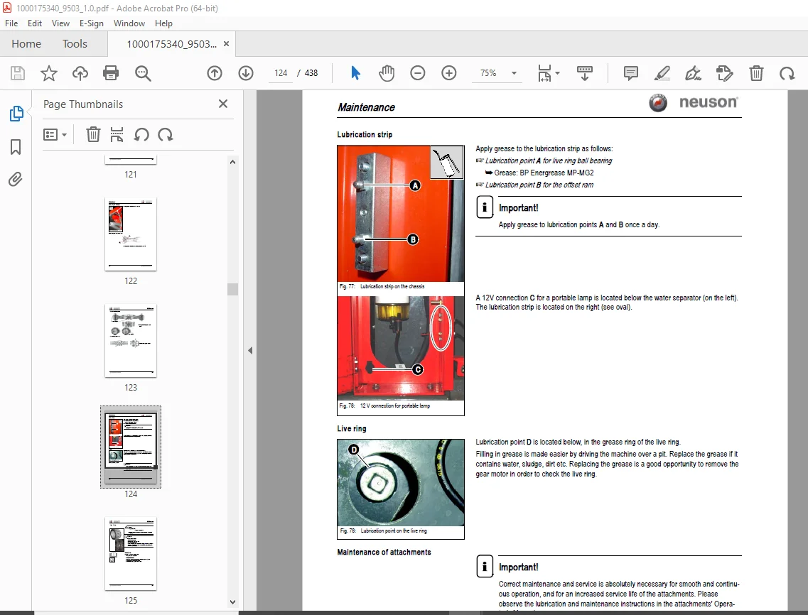
Lubrication strip 3-59
Live ring 3-59
Maintenance of attachments 3-59
Tyres 3-60
Changing tyres 3-61
Cardan shaft 3-62
Daily checks 3-62
Lubrication work 3-62
Central lubrication system (option) 3-63
Function 3-63
Adjusting breaks and lubrication times 3-64
Repair in case of clogging 3-64
Electric system 3-66
Specific safety instructions 3-66
Service and maintenance work at regular intervals 3-66
Instructions concerning specific components 3-67
Alternator 3-67
Checking/replacing the battery 3-68
Cab 3-69
Replacing the fresh/recirculated-air filter 3-69
General maintenance work 3-70
Cleaning 3-70
General instructions for all areas of the machine 3-70
Inside the cab 3-71
Exterior of the machine 3-71
Engine compartment 3-71
Screw connections and attachments 3-71
Pivots and hinges 3-71
Engine
Overview of TCD 2012 2V L04 engine (turbocharger side) 4-1
Fuel circuit diagram 4-3
Coolant system (overview) 4-4
Remove the valve cover 4-5
Checking and adjusting valve tip clearance 4-5
Checking valve tip clearance 4-5
Setting valve tip clearance 4-6
Removing the cylinder head 4-6
Installing the cylinder head 4-7
Checking the fuel injectors 4-8
Setting the fuel injectors 4-8
Checking the nozzle jet 4-9
Injection time 4-9
Determining the shim thickness for start of delivery 4-12
Calculation example: TCD 2012 2V 4-13
Adjusting engine revs 4-14
Checking the compression pressure 4-14
Checking the coolant thermostat 4-15
Removing/mounting the coolant temperature sensor 4-16
Oil pressure switch 4-17
Checking the coolant circuit 4-17
SERV-HB 9503 EN – Edition 1 0 * 9503s10IVZ fm I-5
Table of contents
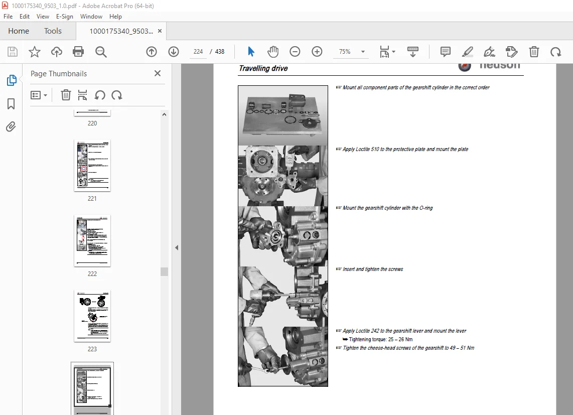
Travelling drive
Hydrostat 5-1
Insert 5-1
Benefits 5-1
Closed circuit with inching valve 5-2
speed-sensitive pump and speed-sensitive motor ports (overview) 5-3
Hydraulic motor A6VM 5-4
General 5-5
Variants 5-6
Mode of function of the bent-axis motor 5-6
Speed-sensitive regulation 5-6
Hydraulic motor diagram A6 VM 107 5-7
Hydraulic motor diagram A6 VM 80 (option) 5-8
Flush valve 5-8
Excavator operation with hydraulic accelerator pedal 5-8
Replacing external components (hydraulic motor) 5-9
Replacing the rotary shaft lip seal 5-10
Replacing seals 5-11
Control unit 5-11
Sealing the cover 5-13
Hydraulic motor settings 5-15
Checking control initiation 5-15
Measurement curve 5-16
Setting the cardan shaft revs 5-17
A 4 VG 56 DA1DX hydraulic pump 5-18
Closed circuit 5-18
Pump design 5-19
Mode of function of the speed-sensitive pump 5-19
Mode of function of the speed-sensitive control valve in the hydraulic circuit 5-20
Hydraulic pump diagram 5-21
Travelling drive circuit (20 kph) 5-22
Power train diagram (20 kph) 5-23
Inching valve 5-24
Inching 5-24
Adjustment work on the hydraulic pump 5-25
Starting RPMs 5-25
Adjusting boost pressure 5-25
Adjusting control pressure 5-26
High pressure/drive pressure 5-26
Replacing components (hydraulic pump) 5-27
Replacing the rotary shaft lip seal 5-27
Seals 5-28
Auxiliary (boost) pump 5-31
Replacing the inching valve 5-31
20 kph gearbox 5-33
Gearbox position on hydraulic motor 5-33
20 kph transfer gearbox: overview 5-34
Removing the 20 kph gearbox 5-35
Installing the 20 kph gearbox 5-39
40 kph gearbox (option) 5-50
Gearbox mounting on hydraulic motor (option) 5-51
40 kph standstill gearbox: overview 5-51
Removing the 40 kph gearbox 5-52
Installing the 40 kph gearbox 5-58
Towing the mobile excavator 5-68
Safety instructions 5-68
Towing 5-69
I-6 SERV-HB 9503 EN – Edition 1 0 * 9503s10IVZ fm
Table of contents
Opening the “Drive” hydraulic circuit 5-69
Unlocking the hydraulic parking brake in an emergency 5-71
Adjusting the hydraulic parking brake after it has been unlocked in an emergency
5-71
Axles
Overview of oil filler necks and type label 6-1
Conversion table and tightening torques 6-2
Removing the joint housing (front axle) 6-3
Assembling the joint housing (front axle) 6-4
Removing the double cardan shaft (front axle) 6-6
Mounting the double cardan shaft (front axle) 6-7
Removing the double cardan shaft (rear axle) 6-8
Assembling the joint housing (rear axle) 6-9
Removing the planetary drives (front axle) 6-11
Replacing the planetary drive seals (front axle) 6-13
Installing the front axle planetary drive 6-14
Removing the rear axle planetary drive 6-17
Mounting the rear axle planetary drive 6-20
Sealing the front axle differential 6-24
Removing the front axle differential lock 6-25
Differential lock: overview 6-27
Installing the front axle differential lock 6-28
Cardan shaft 6-30
Overview of special tools 6-31
Brakes
Service brake 7-1
Brake valve hydraulic diagram 7-2
Overview 7-3
Brake overview 7-4
Replacing the front axle brake discs 7-5
Replacing the rear axle brake discs 7-7
Mounting the brake piston 7-16
Parking brake 7-17
Removing the parking brake 7-18
Mounting the parking brake 7-19
Hydraulic brake 7-21
Removing the outer hydraulic negative brake 7-21
Installing the outer hydraulic negative brake 7-23
Special tools 7-25
Steering system
Front axle steering: overview 8-1
4 wheel steering (option): overview 8-2
Steering direction changeover (option): overview 8-3
Removing the steering rams 8-4
Steering rams: overview 8-5
Installing the steering rams 8-7
Adjusting the steering angle 8-12
Special tools 8-13
Hydraulic system
Pump unit HA 10 VO 74 DFSR/31R and A 4 VG 56 DA1DX 9-1
(LS) work pump HA 10 VO 74 DFSR/31R 9-2
Function 9-2
Settings 9-3
Pump unit overview 9-4
SERV-HB 9503 EN – Edition 1 0 * 9503s10IVZ fm I-7
Table of contents
Gear pumps 9-6
Pilot oil supply unit 9-7
Pilot oil supply unit diagram 9-8
Main valve block SX 14 and SM 12 9-9
Features 9-9
Functions 9-9
Load Sensing/LUDV 9-10
Section SX 14 9-11
Symbol 9-11
Exploded view 9-12
Section SM 12 9-13
Main valve block 9-14
Ports 9-14
Hydraulics diagram 9-16
Hydraulics diagram legend 9-17
Hydraulics diagram – options 9-18
Main valve block diagram and legend 9-19
Pressure limiting valves 9-20
Pump assignment 9-21
Pilot valves 9-22
Joystick 9-22
Joystick legend 9-23
Pilot valve drive work position 9-24
Pilot valve for auxiliary hydraulics 9-25
Steering unit 9-26
Function 9-26
Diagram 9-26
Overview 9-27
Steering system 9-28
Priority valve LPS 40 R11/LD7-543/01-700S 9-29
Function 9-29
Priority valve diagram 9-30
Other valves 9-31
Chassis overview 9-31
7/2 directional valve (changeover valve) 52 9-32
Shuttle valve block 53 9-33
Changeover valve SAE/ISO controls 72 (option) 9-34
Proportional valve 65 (option) 9-35
Distributing block 47 9-35
Offset ram counterbalance valve 62 9-36
Partition wall and undercarriage: overview 9-36
Valve block 20/40 kph (6) 9-37
Steering direction changeover valve 33 (option) 9-37
4-fold outrigger valve block (66) 9-38
Steering mode valve 34 9-38
Swivel unit 9-39
Anti Swing Back (ASB) valve 9-40
Slewing brake 9-45
Pressure cutoff valve 9-46
Diagram 9-46
Swivel joint 9-47
Breather filter 9-48
Malfunctions in the hydraulic system 9-49
Hydraulics diagram A4 9-50
Hydraulics diagram: legend 9-51
I-8 SERV-HB 9503 EN – Edition 1 0 * 9503s10IVZ fm
Table of contents
Electric system
Ohm’s Law (current, voltage, resistance); power 10-1
Measuring equipment, measuring methods 10-1
Cable colour coding 10-3
Relays 10-3
Use, mode of function 10-3
Electric units 10-4
Fuse box 10-4
Main fuse box with relays on partition wall 10-5
Instrument panel overview 10-6
Switches: overview 10-7
Joystick tip switch 10-8
Joystick (left) 10-8
Joystick (right) 10-8
Alternator 10-8
Starter 10-8
Wiring diagram A4: legend 10-10
Wiring diagram page 1 10-11
Wiring diagram page 2 10-12
Wiring diagram page 3 10-13
Wiring diagram page 4 10-14
Engine wiring harness legend 10-15
Engine wiring harness 10-16
Chassis wiring harness legend 10-17
Chassis wiring harness 10-18
Switches wiring harness: legend 10-19
Switches wiring harness 10-21
Cab wiring harness: legend 10-22
Cab wiring harness 10-23
Boom light legend and wiring harness 10-24
Rear lights legend and wiring harness 10-25
Steering legend and wiring harness 10-26
Steering column wiring harness 10-27
Outriggers legend and wiring harness 10-28
Wiring diagram A3: legend 10-31
Wiring diagram A3 (page 1) 10-32
Wiring diagram A3 (page 2) 10-33
Wiring diagram A3 (page 3) 10-34
Wiring diagram A3 (page 4) 10-35
Engine wiring harness legend A3 10-36
Engine wiring harness A3 10-37
Chassis wiring harness legend A3 10-38
Chassis wiring harness A3 10-39
Switches wiring harness A3: legend 10-40
Switches wiring harness A3 10-41
Cab wiring harness A3: legend 10-42
Cab wiring harness A3 10-43
Boom light legend and wiring harness A3 10-44
Rear lights legend and wiring harness A3 10-45
Steering legend and wiring harness A3 10-46
Steering column wiring harness A3 10-47
Outriggers legend and wiring harness A3 10-48
SERV-HB 9503 EN – Edition 1 0 * 9503s10IVZ fm I-9
Table of contents
Options
Air conditioning 11-1
Specific safety instructions 11-1
Specifications 11-1
Installation overview 11-2
Components 11-3
Filling up the air conditioning system 11-5
Maintenance 11-6
Fresh/recirculated air filter 11-7
Troubleshooting 11-8
Air-suspension seat 11-10
Ports 11-10
Long stick 11-10
Specifications 11-10
3rd control circuit connections 11-11
Diagram 11-11
Auxiliary hydraulics connections 11-12
Quickhitch couplings 11-12
Attachments 11-13
Fuel-filling pump (option) 11-13
Ports 11-13
Central lubrication system 11-14
Position 11-14
Function 11-15
Adjusting breaks and lubrication times 11-16
Repair in case of clogging 11-16
Service valve 11-18
Function 11-18
Safe load indicator DE (safety valve for boom) 11-19
Position 11-19
Setting the pressure switch 11-19
Function 11-20
Diagram 11-20
Safe load indicator FR (safety valves for boom and stick) 11-21
Position 11-21
Setting the pressure switch 11-21
Function 11-22
Diagram 11-22
Hose burst valve safety feature DE/FR (option) 11-23
Triple articulation boom 11-24
Function 11-24
Diagram 11-24
Proportional controls for auxiliary hydraulics 11-25
Function 11-25
Diagram 11-25
Drive interlock (antitheft protection) 11-26
Position 11-26
Disabling the drive interlock 11-26
Enabling the drive interlock 11-26
Programming 11-26
Quickhitch 11-28
Control lever with proportional controls (overview) 11-29
Function 11-29
Operating the boom/auxiliary hydraulics 11-30
Hammer operation 11-30
Adjusting control response 11-30
Characteristic curves – status display 11-30
I-10 SERV-HB 9503 EN – Edition 1 0 * 9503s10IVZ fm
Table of contents
Measures to be taken in case of malfunctions 11-31
Control lever with 3rd control circuit (overview) 11-32
Right-hand side control lever 11-32
Control valve 11-33
Control valve plug assignment 11-33
Safety features 11-34
Measures to be taken in case of malfunctions 11-34
Diagnosis display 11-34
DESCRIPTION:
Wacker Neuson 9503 Mobile Excavator Service Manual 1000175340 – PDF DOWNLOAD
Important information on this service manual:
- This manual contains important information on how to service your machine safely, correctly
and economically. Therefore, it aims not only at new operators, but it also serves as
a reference for experienced ones. It helps to avoid dangerous situations and reduce repair
costs and downtimes. Furthermore, the reliability and the service life of the machine will be
increased by following the instructions in the service manual.
Careful and prudent working is the best way to avoid accidents! - Operational safety and readiness of the machine do not only depend on your skill, but also
on maintenance and servicing of the machine. - Insist on using original spare parts when carrying out maintenance and repair work. This
ensures operational safety and readiness of your machine, and maintains its value. - Your Neuson After-Sales Service will be pleased to answer any further questions regarding
the machine or the service manual.
S.V 31/12/24