

Wacker Neuson 50Z3/6003 50Z32/60032 Track excavators Operator’s Manual – PDF DOWNLOAD
IMAGES PREVIEW OF THE MANUAL:
DESCRIPTION:
Wacker Neuson 50Z3/6003 50Z32/60032 Track excavators Operator’s Manual – PDF DOWNLOAD
1 Introduction
1.1 Notices on this Operator’s Manual
- The Operator’s Manual is stored in the document box behind the seat. This Operator’s Manual contains important information on how to work safely, correctly and economically with the machine. Therefore, it aims not only at new personnel, but it also serves as a reference for experienced personnel.
- It helps to avoid dangerous situations and reduce repair costs and downtimes. Furthermore, the reliability and the service life of the machine will be increased by following the instructions in the Operator’s Manual. This is why the Operator’s Manual must always be kept at hand in the machine.
- Your own safety, as well as the safety of others, depends to a great extent on how the machine is moved and operated. Carefully read the Operator’s Manual before putting the machine into operation. This Operator’s Manual will help to familiarize yourself more easily with the machine, thereby enabling you to use it more safely and efficiently.
Notice!
Careful and prudent working is the best way to avoid accidents
- Operational safety and readiness of the machine do not only depend on your skill, but also on maintenance and servicing of the machine. This is why regular maintenance and ser- vice work is absolutely necessary.
- Extensive maintenance and repair work must always be performed by an expert with appropriate training. Use only original spare parts for repairs. T erational safety and readiness of your machine, and maintains its value.
• Special equipment and superstructures are not described in this Operator’s Manual.
• Wacker Neuson reserves the right to improve the technical standard of our machines without adapting the Operator’s Manual.
• Modifying Wacker Neuson products and fitting them with additional equipment and attachments not included in our delivery program requires Wacker Neuson’s written authorization, otherwise warranty and product liability for possible damage caused by these modifications shall not be applicable.
• Subject to modifications and printing errors. Your Wacker Neuson dealer will be pleased to answer any further questions regarding the machine or the Operator’s Manual.
TABLE OF CONTENTS:
Wacker Neuson 50Z3/6003 50Z32/60032 Track excavators Operator’s Manual – PDF DOWNLOAD
Introduction
Notices on this Operator’s Manual 1-1
Abbreviations/symbols 1-2
Machine overview 1-3
Overview of model designations and trade names 1-4
Brief description 1-4
Travelling drive 1-4
Work hydraulics 1-4
Shock cartridges (option) 1-4
Cooling system 1-4
Cab 1-5
Fields of application, attachments 1-6
Use: attachment 1-6
Regulations 1-8
EC declaration of conformity for all machines delivered before 29 December 2009 1-9
EC declaration of conformity for all machines delivered after 29 December 2009 1-10
Declaration of conformity for machines without CE mark on the type label 1-11
EC declaration of conformity for all machines delivered before 29 December 2009
1-12
EC declaration of conformity for all machines delivered after 29 December 2009 1-13
Declaration of conformity for machines without CE mark on the type label 1-14
Type labels and component numbers 1-15
Signs and symbols 1-18
Overview of adhesive labels 1-18
Overview of safety labels 1-23
Fire extinguisher 1-28
Safety instructions
Identification of warnings and dangers 2-1
Warranty 2-1
Disposal 2-1
Designated use and exemption from liability 2-2
General conduct and safety instructions 2-3
Organizational measures 2-3
Selection and qualification of personnel, basic responsibilities 2-4
Safety instructions regarding operation 2-5
Normal operation 2-5
Information on visibility 2-6
Checks when reversing the machine 2-7
Trailer operation 2-7
Applications with lifting gear 2-8
Instructions on fastening loads 2-8
Prerequisite for safe use 2-9
Attachments 2-9
Safety instructions for maintenance 2-10
Warning of special hazards 2-12
Electrical energy 2-12
Working in the area of underground electric lines 2-12
Working near overhead electric lines 2-12
Gas, dust, steam, smoke 2-13
Hydraulic system 2-13
Noise 2-13
Oil, grease and other chemical substances 2-13
Using the quickhitches in water 2-13
Battery 2-14
Table of contents
I-2 BA 50Z3/6003 en – Edition 43 * * Ba5003en4_3IVZfm
Table of contents
Tracks 2-14
Hammer operation 2-14
Safety instructions 2-14
Working with a hammer 2-15
Transport and towing 2-15
Towing 2-15
Transport 2-15
Operation
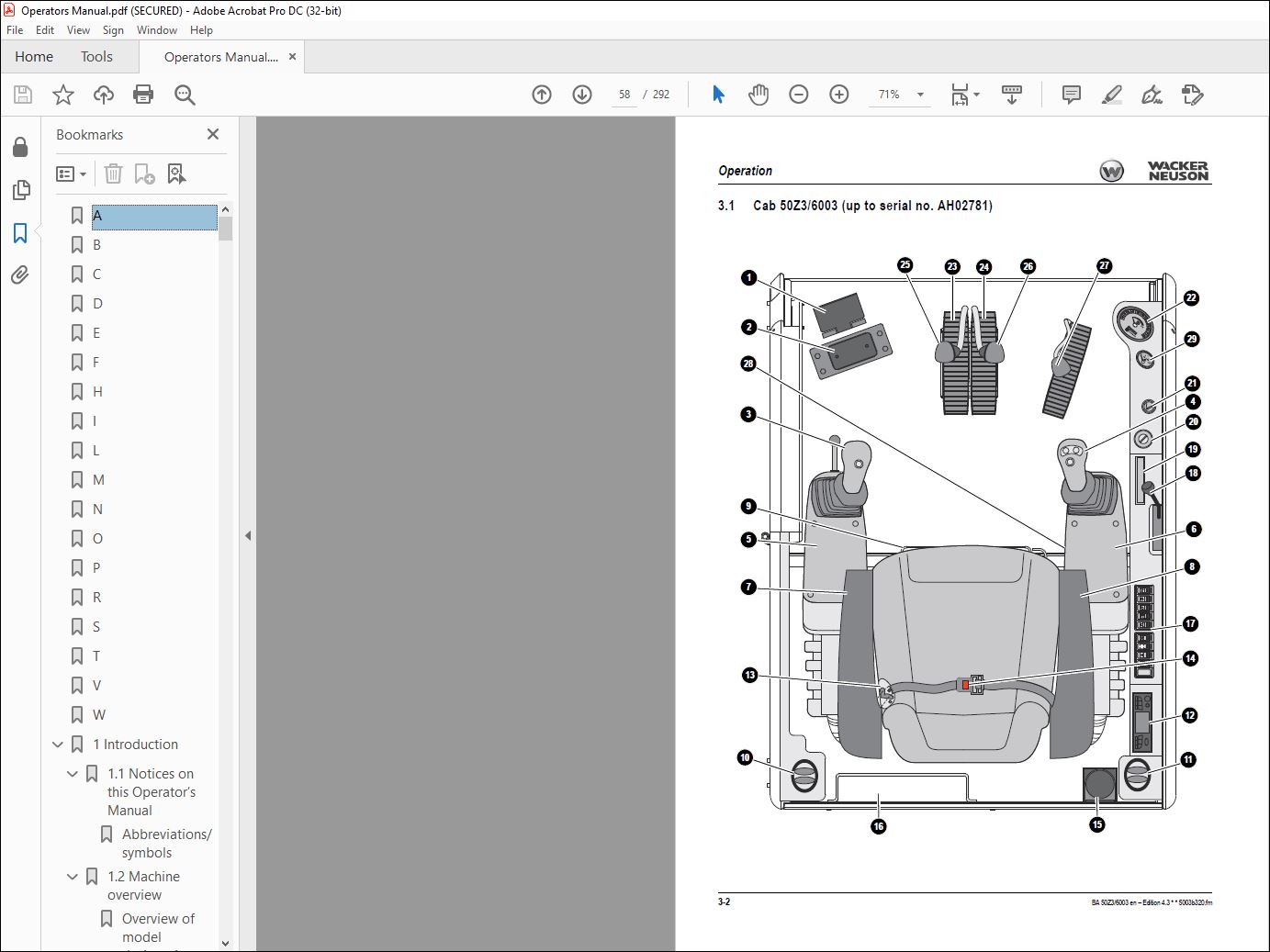
Cab 50Z3/6003 (up to serial no AH02781) 3-2
Cab 50Z3 2 / 6003 2 (from serial no AJ02777) 3-4
Control elements 50Z3 (up to serial no AH02781) / 6003 (up to serial no AH00578)
3-6
Control elements 6003 (serial nos AH00579 to AH02750) 3-7
Control elements 50Z3 2 / 6003 2 (from serial noAJ02777) 3-9
Indicator lights and warning lights (overview) 3-11
Putting into operation 3-14
Safety instructions 3-14
Putting the machine into operation for the first time 3-14
Running-in period 3-14
Check lists 3-15
Start-up checklist 3-15
Operation checklist 3-16
Parking checklist 3-16
Driving the machine 3-17
Preheating start switch 3-17
Throttle 3-17
Automatic engine speed setting 3-18
Before starting the engine 3-19
Starting the engine: general 3-20
Starting with the drive interlock – internal transponder (option) (from serial no AJ02777)
3-21
Jump-starting the engine (supply battery) 3-22
Starting at low temperatures 3-23
When the engine has started 3-23
Special instructions for driving on public roads 3-24
Drive position 3-24
Drive levers 3-24
High speed 3-25
Moving off 3-25
Hydraulic brake 3-25
Mechanical brake 3-25
Working on slopes 3-26
Stabilizer blade operation 3-28
Parking the machine 3-29
Parking the machine on slopes 3-29
Light system 3-30
Working lights 3-30
Roof lights (option) 3-31
Interior light 3-31
Rotating beacon (option) 3-32
Cab heating and ventilation 3-33
Summer/winter operation (up to serial no AD04650) 3-34
Heating controls (from serial no AD04651) 3-34
Air conditioning (option) 3-35
Recirculated air mode 3-35
BA 50Z3/6003 en – Edition 43 * Ba5003en4_3IVZfm I-3
Table of contents
Wiper/wash system 3-36
Tank for washer system 3-36
Seat (50Z3) 3-37
Weight adjustment 3-38
Height adjustment 3-38
Horizontal adjustment 3-38
Backrest adjustment 3-38
Seat (6003) 3-39
Weight adjustment 3-40
Horizontal adjustment 3-40
Seat depth adjustment 3-40
Backrest adjustment 3-40
Head rests 3-41
Height adjustment 3-41
Seat (air suspension option) 3-42
Weight adjustment 3-43
Height adjustment 3-43
Horizontal adjustment 3-43
Seat depth adjustment 3-43
Backrest adjustment 3-44
Adjusting the head rest 3-44
Horizontal suspension 3-44
Seat belt 3-45
Retracting lap belt (option) 3-46
Mirrors (option) 3-47
Safety instructions 3-47
Adjusting the mirrors 3-48
Emergency exit 3-49
Emergency exit on machines equipped with protective Front Guard structures
(option) 3-49
Front window (up to serial no AD06526) 3-50
Front window (from serial no AD06527) 3-51
Opening the front window 3-51
Closing the front window 3-52
Opening the lower front window 3-53
Closing the lower front window 3-53
Opening the whole front window 3-54
Closing the whole front window 3-55
Opening the front window to a gap 3-56
Opening and closing the side window 3-56
Mounting/removing the canopy shatter protection (option) 3-57
Door 3-58
Door 50Z3 3-58
Door 6003 3-58
Exit through the door (up to serial no AH02764) 3-60
Exit through the door (from serial no AJ02777) 3-61
Armrest adjustment (up to serial no AH02764) 3-62
Armrest adjustment (from serial no AJ02777) 3-63
Engine cover 3-63
Battery master switch 3-64
Raising/lowering the cab 3-65
Towing the machine 3-68
Crane handling the machine 3-69
Loading and transporting the machine 3-71
Safety instructions 3-71
I-4 BA 50Z3/6003 en – Edition 43 * * Ba5003en4_3IVZfm
Table of contents
Tying down the machine 3-72
Travelling signal (option) 3-72
Protective structures 3-73
Definition of the term “Protective Structure” 3-73
Mechanical integrity 3-73
Definition of FOPS/Front Guard categories 3-73
Responsibility for machine equipped with protective structures 3-73
Protective FOPS structure/small screen – category I (option) 3-74
Protective FOPS structure/large screen – category II (option) 3-75
Protective Front Guard structure category II (option) 3-76
Shatter protection (50Z3 option) 3-78
Emergency exit 3-80
Emergency exit for cab equipped with protective Front Guard structure 3-80
Working with the machine 3-82
General safety instructions 3-82
Control levers/ISO controls: overview 3-83
Left-hand control lever 3-83
Hammer pedal lock (up to serial no AH02781) 3-83
Boom/triple articulation boom operation (up to serial no AH02781) 3-84
Hammer pedal lock (from serial no AJ02777) 3-84
Boom/triple articulation boom operation (from serial no AJ02777) 3-85
Right-hand control lever 3-85
Lowering the boom with the engine stopped 3-85
Rotating the upper carriage 3-86
Swivel unit brake 3-86
Changeover valve for SAE/ISO controls (option) 3-87
Left-hand control lever 3-87
Right-hand control lever 3-87
Directional valve position 3-87
Directional valve 3-88
Control lever with proportional controls (option): overview 3-89
Function 3-89
Left-hand control lever 3-90
Changeover between auxiliary hydraulics and boom swivel 3-90
Switching the status indicator on/off for auxiliary hydraulics/boom swivel 3-90
Operating the boom/auxiliary hydraulics 3-91
Hammer operation 3-91
Adjusting control response 3-92
Characteristic curve status indicator 3-92
Lowering the boom with the engine stopped 3-93
Releasing pressure 3-93
Control lever if equipped with 3rd control circuit (option): overview 3-94
Left-hand control lever 3-94
Boom swivel controls (up to serial no AH02781) 3-94
Boom swivel controls (from serial number AJ02777) 3-95
Right-hand control lever 3-95
Right-hand control lever if equipped with proportionally controlled 3rd control circuit
(option) 3-96
Lowering the boom with the engine stopped 3-96
Releasing pressure 3-96
Tilting the upper carriage – Vertical Digging System (option) 3-97
Operation (up to serial no AH02781) 3-98
Operation (from serial no AJ02777) 3-98
Vario (6003 option) 3-99
Vario operation 3-99
Driving across slopes with the Vario feature 3-99
Risk zone of the Vario feature 3-100
BA 50Z3/6003 en – Edition 43 * Ba5003en4_3IVZfm I-5
Table of contents
Working with the Vario feature 3-101
Improved reach with the Vario feature 3-101
Releasing the pressure on the operating hydraulics 3-102
Releasing pressure 3-102
Pressure release with proportional controls (option) 3-102
Re-equipping attachments 3-103
Specific safety instructions 3-103
Removing a bucket 3-103
Installing a bucket 3-104
Quickhitch (option) 3-104
Hydraulic Easy Lock quickhitch (option) 3-106
Powertilt (option) 3-110
Re-equipping 3-110
Operation 3-111
Right-hand control lever (Powertilt) 3-111
Connections for auxiliary hydraulics 3-112
Quickhitch couplings 3-112
Safe load indicator (option) 3-113
Safety feature “Hose burst valve” (option) 3-114
Applications with lifting gear 3-114
Lifting gear applications 3-115
Fastening loads 3-115
Work area assessment and preparation 3-115
Examining the site 3-115
Preparing the ground 3-115
Working with the machine 3-116
Working with the standard bucket 3-116
Inadmissible work 3-116
Work position of machine 3-117
Bucket position when digging 3-118
Excavating trenches 3-118
Loading 3-119
Grading 3-119
Excavating trenches sideways 3-119
Working alongside trenches 3-120
Stabilizer blade at rear 3-120
Further practical hints for digging 3-121
Loading vehicles 3-121
Freeing the machine 3-121
Grading 3-121
Grading 3-121
Troubleshooting
Engine trouble 4-1
Indicator lights 4-3
Seals, hoses 4-3
Travel gear 4-4
Engine error codes 4-5
Malfunctions of the Powertilt unit 4-9
Troubleshooting the central lubrication system (option) 4-10
Proportional controls (option) diagnosis display 4-11
Maintenance
Introduction 5-1
Safety-relevant parts 5-1
Fuel system 5-2
Refuelling 5-3
Fuel-filling pump (option) (up to serial no AD04862) 5-3
I-6 BA 50Z3/6003 en – Edition 43 * * Ba5003en4_3IVZfm
Table of contents
Fuel-filling pump (option) (from serial no AD04863) 5-4
Stationary fuel pumps 5-4
Bleeding the fuel system 5-5
Fuel prefilter with water separator 5-6
Engine lubrication system 5-7
Checking the engine oil level 5-7
Adding engine oil 5-8
Engine and hydraulics cooling system 5-9
Specific safety instructions 5-9
Checking the coolant level/adding coolant 5-10
Air filter 5-12
Replacing the air filter 5-13
Air intake 5-14
Changing the cab air filter 5-14
Replacing the filter element of the air conditioning system (option) 5-15
Diesel particulate filter (option) 5-16
Main components of diesel particulate filter system 5-16
How the diesel particulate filter works 5-17
Machine operation with diesel particulate filter 5-17
Display 5-19
Temperature scale 5-19
Exhaust gas back pressure scale 5-19
Alarm messages 5-20
Maintenance 5-23
Oils and fuels 5-24
Troubleshooting 5-24
Warranty 5-24
V-belt 5-25
Checking V-belt tension 5-25
Retightening the V-belt 5-26
Checking the V-belt of the air conditioning system (option) 5-27
Tightening the V-belt of the air conditioning system 5-27
Hydraulic system 5-28
Specific safety instructions 5-28
Checking the hydraulic oil level 5-29
Adding hydraulic oil 5-30
Important notices on the use of biodegradable oil 5-31
Checking hydraulic pressure lines 5-32
Tracks 5-33
Checking the track tension of the rubber tracks 5-33
Checking the track tension of the steel tracks (option) and hybrid tracks (option)
5-34
Adjusting track tension 5-34
Travelling drive 5-36
Checking the oil level and adding oil 5-36
Draining oil 5-36
Maintenance of attachments 5-37
Electrical system 5-37
Service and maintenance work at regular intervals 5-37
Instructions concerning specific components 5-37
Alternator 5-37
Battery 5-38
General maintenance work 5-40
Cleaning 5-40
General instructions for all areas of the machine 5-40
Inside the cab 5-40
Cleaning the seat belt 5-41
BA 50Z3/6003 en – Edition 43 * Ba5003en4_3IVZfm I-7
Table of contents
Exterior of the machine 5-41
Engine compartment 5-41
Threaded fittings and attachments 5-41
Pivots and hinges 5-41
Overview of lubrication points 5-42
Parking the machine 5-43
Lubrication points on the boom, bucket and stick rams 5-43
Lubrication points on the boom and stick 5-44
Joint rod lubrication point 5-45
Lubrication points on the stabilizer blade and stabilizer blade ram 5-45
Lubrication points on the slewing ram and swivelling console 5-46
Lubrication points of ball bearing race of live ring 5-47
Lubrication points of live ring teeth 5-48
Powertilt lubrication points (option) 5-49
Lubrication points of hydraulic quickhitch (option) 5-49
Lubrication points of control lever base (from serial no AJ02777) 5-50
VDS lubrication points (option) 5-50
Central lubrication system (option) 5-51
Function 5-51
Status LEDs 5-51
Adjusting cycle time and lubrication time 5-52
Repair in case of clogging 5-52
Preparatory work before taking out of service 5-53
Maintenance if the machine is out of service for a longer period of time 5-53
Putting into operation again 5-53
Fluids and lubricants 5-54
Oil grades for the diesel engine, depending on temperature 5-55
Additional oil change and filter replacement (hydraulic system) 5-55
Oil grades for the hydraulic system, depending on temperature 5-56
Maintenance plan (overview) 5-57
Maintenance label 5-62
Explanation of symbols on the maintenance label 5-62
Specifications
Chassis 6-1
Engine 6-1
Hydraulic system 6-2
Operating hydraulics 6-2
Travel gear and swivel unit 6-2
Stabilizer blade 6-2
Electrical system, model 50Z3 6-3
Fuse box in instrument panel 6-3
Main fuse box with relays underneath the cab 6-3
Relays 6-4
Electrical system, model 6003 (from serial no AH0611) 6-4
Fuse box on instrument panel (up to serial no AH02750) 6-4
Main fuse box with relays 6-5
Fuse box on instrument panel (from serial no AJ02777) 6-5
I-8 BA 50Z3/6003 en – Edition 43 * * Ba5003en4_3IVZfm
Table of contents
ECU control unit (6003 from serial no AH00611) 6-6
Noise levels 6-6
Vibration 6-6
6-9
Coolant compound table 6-9
Powertilt 6-9
Weight indications 6-10
Dimensions model 50Z3 6-11
Dimensions model 50Z3 VDS 6-13
Dimensions model 6003 standard boom, Vario (option) 6-15
Dimensions model 6003 triple articulation boom (option) 6-17
Lift capacity table 50Z3 6-19
Lift capacity table 50Z3 counterweight (option) 6-20
Lift capacity table 50Z3 long stick (option) 6-21
Lift capacity table 50Z3 long stick, counterweight (option) 6-22
Lift capacity table 50Z3 VDS short stick (option) 6-23
Lift capacity table 50Z3 VDS short stick, counterweight (option) 6-24
Lift capacity table 50Z3 VDS long stick (option) 6-25
Lift capacity table 50Z3 VDS long stick, counterweight (option) 6-26
Lift capacity table 6003 6-27
Lift capacity table 6003 counterweight (option) 6-28
Lift capacity table 6003 long stick (option) 6-29
Lift capacity table 6003 long stick, counterweight (option) 6-30
Lift capacity table 6003 long stick, triple articulation boom (option) 6-31
Lift capacity table 6003 long stick, triple articulation boom, counterweight (option)
6-32
Lift capacity table 6003 triple articulation boom (option) 6-33
Lift capacity table 6003 triple articulation boom, counterweight (option) 6-34
Lift capacity table 6003 Vario (option) 6-35
Applications with lifting gear
VIDEO PREVIEW OF THE MANUAL:
PLEASE NOTE:
- This is the SAME exact manual used by your dealers to fix your vehicle.
- The same can be yours in the next 2-3 mins as you will be directed to the download page immediately after paying for the manual.
- Any queries / doubts regarding your purchase, please feel free to contact [email protected]
S.M


