WACKER NEUSON 3001 DUMPER SERVICE MANUAL 1000156004 – PDF DOWNLOAD
$27.95
WACKER NEUSON 3001 DUMPER SERVICE MANUAL 1000156004 – PDF DOWNLOAD
Description
WACKER NEUSON 3001 DUMPER SERVICE MANUAL 1000156004 – PDF DOWNLOAD
FILE DETAILS:
WACKER NEUSON 3001 DUMPER SERVICE MANUAL 1000156004 – PDF DOWNLOAD
Language : English
Pages : 214
Downloadable : Yes
File Type : PDF
IMAGES PREVIEW OF THE MANUAL:
TABLE OF CONTENTS:
WACKER NEUSON 3001 DUMPER SERVICE MANUAL 1000156004 – PDF DOWNLOAD
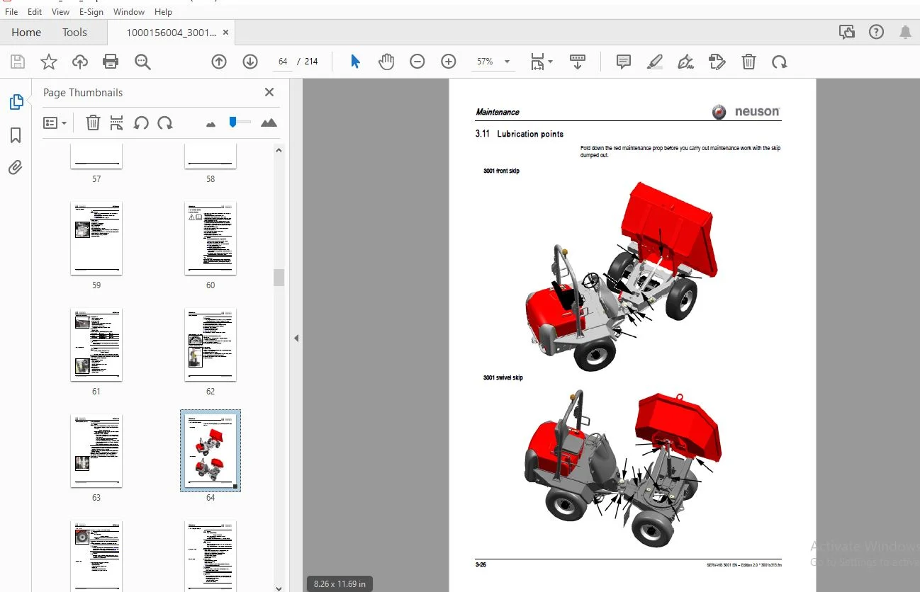
Important information on this service manual 1-1.................................................................  3
Identification of warnings and dangers 1-2.......................................................................  3
Designated use and exemption from liability 1-3..................................................................  3
Type labels and component numbers 1-4............................................................................  3
Description of 3001F components (overview) 1-6...................................................................  3
Description of 3001S components (overview) 1-7...................................................................  3
Control stand overview 1-8.......................................................................................  3
Instrument panel overview 1-9....................................................................................  3
Front skip maintenance prop 1-10.................................................................................  3
Swivel skip maintenance prop 1-10................................................................................  3
Rollbar 1-11.....................................................................................................  3
Centre pivot prop 1-11...........................................................................................  3
Locking the control levers 1-12..................................................................................  3
Battery master switch 1-12.......................................................................................  3
Chassis 2-1......................................................................................................  3
Engine 2-1.......................................................................................................  3
Travelling drive 2-2.............................................................................................  3
Brakes 2-2.......................................................................................................  3
Steering system 2-2..............................................................................................  3
Work hydraulics 2-3..............................................................................................  3
Skip 2-3.........................................................................................................  3
Drive specifications 2-3.........................................................................................  3
Vibration 2-3....................................................................................................  3
Electric system 2-4..............................................................................................  3
Tyres 2-5........................................................................................................  3
Noise levels 2-5.................................................................................................  3
Coolant compound table 2-5.......................................................................................  3
General tightening torques 2-6...................................................................................  3
Dimensions model 3001 front skip 2-10............................................................................  3
Dimensions model 3001 swivel skip 2-11...........................................................................  3
Fluids and lubricants 3-1........................................................................................  3
Maintenance plan (overview) 3-3..................................................................................  3
Service package 3-6..............................................................................................  3
Introduction 3-6.................................................................................................  3
Fuel system 3-7..................................................................................................  3
Engine lubrication system 3-11...................................................................................  4
Cooling system 3-15..............................................................................................  4
Air filter 3-18..................................................................................................  4
V-belt 3-20......................................................................................................  4
Hydraulic system 3-22............................................................................................  4
Lubrication points 3-26..........................................................................................  4
Tyres 3-27.......................................................................................................  4
Changing wheels 3-28.............................................................................................  4
Axles 3-29.......................................................................................................  4
Electric system 3-30.............................................................................................  4
Battery master switch 3-33.......................................................................................  4
General maintenance work 3-34....................................................................................  4
3TNV88-KNSV engine: overview 4-1.................................................................................  4
Fuel system (up to AB) 4-3.......................................................................................  4
Fuel system (starting AC) 4-4....................................................................................  4
Checking the injection nozzles 4-7...............................................................................  4
Adjusting engine revs 4-9........................................................................................  4
Compression 4-9..................................................................................................  4
Checking the coolant thermostat 4-10.............................................................................  5
Oil pressure switch 4-11.........................................................................................  5
Checking the coolant circuit 4-11................................................................................  5
Clutch 4-12......................................................................................................  5
Engine 3TNV88-BKNSV overview (from serial no. AE310242D) 4-13....................................................  5
Fuel system (from serial no. AE310242D) 4-15.....................................................................  5
Checking the injection nozzles 4-18..............................................................................  5
Adjusting engine revs 4-20.......................................................................................  5
Automatic revs setting option (Tier 3A from AE310242D) 4-20......................................................  5
Compression 4-22.................................................................................................  5
Checking the coolant thermostat 4-22.............................................................................  5
Oil pressure switch 4-23.........................................................................................  5
Checking the coolant circuit 4-23................................................................................  5
Clutch 4-24......................................................................................................  5
Engine trouble 4-24..............................................................................................  5
Variable displacement pump A10VG45DA 5-1.........................................................................  5
A6VM80EZ hydraulic motor 5-7.....................................................................................  5
Travelling drive overview (up to AB) 5-8.........................................................................  5
Travelling drive overview (starting AC) 5-8......................................................................  5
Towing and transporting the machine 5-9..........................................................................  5
Test instruction 5-10............................................................................................  5
Adjustment 5-13..................................................................................................  5
Axle type label 6-1..............................................................................................  5
Drain, fill and check plug 6-2...................................................................................  5
Tightening torques 6-2...........................................................................................  5
Articulated joint (up to AB) 6-4.................................................................................  5
Articulated joint (starting AC) 6-6..............................................................................  5
Transfer gearbox (up to AD) 6-8..................................................................................  5
Transfer gearbox (from AE310242D) 6-10...........................................................................  5
Semiaxles 6-12...................................................................................................  5
Wheel hub 6-14...................................................................................................  5
Front axle brake (up to AB) 6-16.................................................................................  5
Brake diagram 6-17...............................................................................................  6
Front axle brake (starting AC up to AD) 6-20.....................................................................  6
Front axle brake (from AE310242D) 6-21...........................................................................  6
Differential (up to AB) 6-23.....................................................................................  6
Cardan shaft 6-32................................................................................................  6
Brake circuit (up to AB) 7-1.....................................................................................  6
Brake circuit (starting AC) 7-2..................................................................................  6
Steering circuit (up to AB) 8-1..................................................................................  6
Steering circuit (starting AC) 8-2...............................................................................  6
Steering unit: diagram 8-3.......................................................................................  6
Steering unit connections 8-4....................................................................................  6
Steering unit overview 8-5.......................................................................................  6
Manual spool connections: overview 9-1...........................................................................  6
Valves - differential lock (up to AB) 9-2........................................................................  6
Dumping the skip: hydraulic diagram (up to AB) 9-3...............................................................  6
Dumping the skip: hydraulic diagram (starting AC) 9-4............................................................  6
Swivelling the skip: hydraulics diagram (up to AB) 9-5...........................................................  6
Swivelling the skip: hydraulics diagram (starting AC) 9-6........................................................  6
Test instructions 9-7............................................................................................  6
Diagram A4 (up to AB) 9-8........................................................................................  6
Diagram legend (up to AB) 9-9....................................................................................  6
Diagram A4 (starting AC) 9-10....................................................................................  6
Diagram legend (starting AC) 9-11................................................................................  6
Ohm's Law (current, voltage, resistance); power 10-1.............................................................  6
Measuring equipment, measuring methods 10-1......................................................................  6
Relays 10-2......................................................................................................  6
Electric units 10-3..............................................................................................  6
Control stand overview 10-4......................................................................................  6
Instrument panel overview 10-5...................................................................................  6
Wiring diagram (legend) 10-7.....................................................................................  6
Wiring diagram version 1 A4 10-8.................................................................................  6
Wiring harness 1000115009 main wiring harness up to AB (legend) 10-9.............................................  6
Wiring harness 1000115009 main wiring harness up to AB 10-11.....................................................  6
Wiring harness 1000173558 main wiring harness starting AC (legend) 10-12.........................................  6
Wiring harness 1000173558 main wiring harness starting AC 10-14..................................................  6
Wiring diagram A3 up to AB (legend) 10-16........................................................................  6
Wiring diagram A3 (up to AB) 10-17...............................................................................  7
Wiring harness 1000115009 main wiring harness up to AB (legend) 10-18............................................  7
Wiring harness 1000115009 main wiring harness up to AB 10-19.....................................................  7
Wiring harness 1000173558 main wiring harness starting AC (legend) 10-20.........................................  7
Wiring harness 1000173558 main wiring harness starting AC 10-21..................................................  7
Wiring harness 1000115414 engine wiring harness (legend) 10-22...................................................  7
Wiring harness 1000115414 engine wiring harness 10-23............................................................  7
Wiring harness 1000075039/1000079012 telltale/indicator base - ignition lock base up to AB (legend) 10-24........  7
Wiring harness 1000075039 telltale/indicator base (up to AB) 10-25...............................................  7
Wiring harness 1000173351 ignition lock base starting AC 10-26...................................................  7
Light switch connector assignment 10-27..........................................................................  7
Legend and STVO wiring harness (Austrian road traffic regulations) 1000166512 (starting AC) 10-28................  7
Extension cable (front skip) 1000166698 10-29....................................................................  7
A................................................................................................................  8
F................................................................................................................  8
I................................................................................................................  8
M................................................................................................................  8
O................................................................................................................  8
P................................................................................................................  8
R................................................................................................................  8
S................................................................................................................  8
T................................................................................................................  8
W................................................................................................................  8
	Operation....................................................................................................  9
1 Operation...................................................................................................... 11
	1.1 Important information on this service manual............................................................. 11
	1.2 Identification of warnings and dangers................................................................... 12
	1.3 Designated use and exemption from liability.............................................................. 13
	1.4 Type labels and component numbers........................................................................ 14
	1.5 Description of 3001F components (overview)............................................................... 16
	1.6 Description of 3001S components (overview)............................................................... 17
	1.7 Control stand overview................................................................................... 18
	1.8 Instrument panel overview................................................................................ 19
	1.9 Front skip maintenance prop.............................................................................. 20
	1.10 Swivel skip maintenance prop............................................................................ 20
	1.11 Rollbar................................................................................................. 21
	1.12 Centre pivot prop....................................................................................... 21
	1.13 Locking the control levers.............................................................................. 22
	1.14 Battery master switch................................................................................... 22
		Specifications........................................................................................... 23
2 Specifications................................................................................................. 25
	2.1 Chassis.................................................................................................. 25
	2.2 Engine................................................................................................... 25
		Engine capacities........................................................................................ 26
		Engine tightening torques................................................................................ 26
	2.3 Travelling drive......................................................................................... 26
	2.4 Brakes................................................................................................... 26
	2.5 Steering system.......................................................................................... 26
	2.6 Work hydraulics.......................................................................................... 27
	2.7 Skip..................................................................................................... 27
	2.8 Drive specifications..................................................................................... 27
	2.9 Vibration................................................................................................ 27
	2.10 Electric system......................................................................................... 28
		Fuse box................................................................................................. 28
		Relays................................................................................................... 28
	2.11 Tyres................................................................................................... 29
	2.12 Noise levels............................................................................................ 29
	2.13 Coolant compound table.................................................................................. 29
	2.14 General tightening torques.............................................................................. 30
		Tightening torques for hydraulic screw connections (dry assembly)........................................ 30
		Tightening torques for high-resistance screw connections................................................. 32
		Tightening torques for Nordlock lock washers............................................................. 33
	2.15 Dimensions model 3001 front skip........................................................................ 34
	2.16 Dimensions model 3001 swivel skip....................................................................... 35
		Maintenance.............................................................................................. 37
3 Maintenance.................................................................................................... 39
	3.1 Fluids and lubricants.................................................................................... 39
	3.2 Maintenance plan (overview).............................................................................. 41
	3.3 Service package.......................................................................................... 44
		Up to serial no.......................................................................................... 44
		From serial no. AE310242D................................................................................ 44
	3.4 Introduction............................................................................................. 44
	3.5 Fuel system.............................................................................................. 45
		Specific safety instructions............................................................................. 45
		Refuelling............................................................................................... 45
		Stationary fuel pumps.................................................................................... 46
		Diesel fuel specification................................................................................ 46
		Bleeding the fuel system................................................................................. 46
		Fuel prefilter with water separator...................................................................... 47
		Replacing the fuel filter................................................................................ 48
	3.6 Engine lubrication system................................................................................ 49
		Checking the oil level................................................................................... 49
		Filling up engine oil.................................................................................... 50
		Changing engine oil...................................................................................... 51
		Replacing the engine oil filter cartridge................................................................ 52
	3.7 Cooling system........................................................................................... 53
		Specific safety instructions............................................................................. 53
		Checking/filling up coolant.............................................................................. 54
		Draining coolant......................................................................................... 55
	3.8 Air filter............................................................................................... 56
		Replacing the filter..................................................................................... 57
		Functional check once a week of the dust valve........................................................... 57
	3.9 V-belt................................................................................................... 58
		Checking V-belt tension.................................................................................. 58
		Retightening the V-belt.................................................................................. 59
	3.10 Hydraulic system........................................................................................ 60
		Specific safety instructions............................................................................. 60
		Checking the hydraulic oil level......................................................................... 61
		Filling up hydraulic oil................................................................................. 61
		Changing hydraulic oil................................................................................... 62
		Fouling indicator for hydraulic oil filter............................................................... 62
		Replacing the hydraulic oil filter element............................................................... 62
		Checking hydraulic pressure lines........................................................................ 63
	3.11 Lubrication points...................................................................................... 64
	3.12 Tyres................................................................................................... 65
		Inspection work.......................................................................................... 65
	3.13 Changing wheels......................................................................................... 66
		Removing the wheels...................................................................................... 66
		Fitting the wheels....................................................................................... 66
	3.14 Axles................................................................................................... 67
		Checking the oil level and filling up oil................................................................ 67
		Draining oil............................................................................................. 67
	3.15 Electric system......................................................................................... 68
		Specific safety instructions............................................................................. 68
		Service and maintenance work at regular intervals........................................................ 68
		Instructions concerning specific components.............................................................. 69
		Alternator............................................................................................... 69
		Battery.................................................................................................. 70
	3.16 Battery master switch................................................................................... 71
	3.17 General maintenance work................................................................................ 72
		Cleaning................................................................................................. 72
		General instructions for all areas of the machine........................................................ 72
		Screw connections and attachments........................................................................ 72
		Pivots and hinges........................................................................................ 72
			Engine............................................................................................... 73
4 Engine......................................................................................................... 75
	4.1 3TNV88-KNSV engine: overview............................................................................. 75
	4.2 Fuel system (up to AB)................................................................................... 77
	4.3 Fuel system (starting AC)................................................................................ 78
		Checking and adjusting valve clearance................................................................... 79
		Tightening order for cylinder head bolts................................................................. 80
	4.4 Checking the injection nozzles........................................................................... 81
		Pressure check........................................................................................... 81
		Checking the nozzle jet.................................................................................. 81
		Injection time........................................................................................... 82
	4.5 Adjusting engine revs.................................................................................... 83
	4.6 Compression.............................................................................................. 83
	4.7 Checking the coolant thermostat.......................................................................... 84
		Checking the thermal switch.............................................................................. 84
	4.8 Oil pressure switch...................................................................................... 85
	4.9 Checking the coolant circuit............................................................................. 85
	4.10 Clutch.................................................................................................. 86
	4.11 Engine 3TNV88-BKNSV overview (from serial no. AE310242D)................................................ 87
	4.12 Fuel system (from serial no. AE310242D)................................................................. 89
		Checking and adjusting valve clearance................................................................... 90
		Tightening order for cylinder head bolts................................................................. 91
	4.13 Checking the injection nozzles.......................................................................... 92
		Pressure check........................................................................................... 92
		Checking the nozzle jet.................................................................................. 92
		Injection time........................................................................................... 93
	4.14 Adjusting engine revs................................................................................... 94
	4.15 Automatic revs setting option (Tier 3A from AE310242D).................................................. 94
		Function................................................................................................. 94
		Installation............................................................................................. 95
	4.16 Compression............................................................................................. 96
	4.17 Checking the coolant thermostat......................................................................... 96
		Checking the thermal switch.............................................................................. 97
	4.18 Oil pressure switch..................................................................................... 97
	4.19 Checking the coolant circuit............................................................................ 97
	4.20 Clutch.................................................................................................. 98
	4.21 Engine trouble.......................................................................................... 98
		Travelling drive......................................................................................... 99
5 Travelling drive...............................................................................................101
	5.1 Variable displacement pump A10VG45DA.....................................................................101
		Variable displacement pump: diagram......................................................................103
		Variable displacement pump: design.......................................................................104
		Travelling drive overview................................................................................105
		Connecting plate with valves.............................................................................106
	5.2 A6VM80EZ hydraulic motor.................................................................................107
	5.3 Travelling drive overview (up to AB).....................................................................108
	5.4 Travelling drive overview (starting AC)..................................................................108
	5.5 Towing and transporting the machine......................................................................109
		Safety instructions......................................................................................109
		Towing...................................................................................................109
		Opening the high-pressure circuit........................................................................109
	5.6 Test instruction.........................................................................................110
		High pressure check......................................................................................110
		Check: boost pressure....................................................................................111
		Check: setting pressure..................................................................................112
	5.7 Adjustment...............................................................................................113
		Setting: control initiation..............................................................................113
			Axles................................................................................................115
6 Axles..........................................................................................................117
	6.1 Axle type label..........................................................................................117
	6.2 Drain, fill and check plug...............................................................................118
	6.3 Tightening torques.......................................................................................118
		Wheel screws.............................................................................................118
		General tightening torques...............................................................................119
	6.4 Articulated joint (up to AB).............................................................................120
	6.5 Articulated joint (starting AC)..........................................................................122
	6.6 Transfer gearbox (up to AD)..............................................................................124
	6.7 Transfer gearbox (from AE310242D)........................................................................126
	6.8 Semiaxles................................................................................................128
	6.9 Wheel hub................................................................................................130
	6.10 Front axle brake (up to AB).............................................................................132
	6.11 Brake diagram...........................................................................................133
	6.12 Front axle brake (starting AC up to AD).................................................................136
	6.13 Front axle brake (from AE310242D).......................................................................137
	6.14 Differential (up to AB).................................................................................139
		Front axle (up to AB)....................................................................................141
		Front axle (starting AC up to AD)........................................................................143
		Rear axle................................................................................................146
	6.15 Cardan shaft............................................................................................148
7 Brakes.........................................................................................................151
	7.1 Brake circuit (up to AB).................................................................................151
	7.2 Brake circuit (starting AC)..............................................................................152
		Parking brake............................................................................................152
		Service brake............................................................................................154
			Steering system......................................................................................155
8 Steering system................................................................................................157
	8.1 Steering circuit (up to AB)..............................................................................157
	8.2 Steering circuit (starting AC)...........................................................................158
	8.3 Steering unit: diagram...................................................................................159
		Function.................................................................................................159
	8.4 Steering unit connections................................................................................160
	8.5 Steering unit overview...................................................................................161
		Priority valve overview..................................................................................161
		Priority valve (legend)..................................................................................161
		Steering unit............................................................................................162
		Steering unit (legend)...................................................................................163
9 Hydraulic system...............................................................................................167
	9.1 Manual spool connections: overview.......................................................................167
	9.2 Valves - differential lock (up to AB)....................................................................168
		Check valve..............................................................................................168
	9.3 Dumping the skip: hydraulic diagram (up to AB)...........................................................169
	9.4 Dumping the skip: hydraulic diagram (starting AC)........................................................170
	9.5 Swivelling the skip: hydraulics diagram (up to AB).......................................................171
	9.6 Swivelling the skip: hydraulics diagram (starting AC)....................................................172
	9.7 Test instructions........................................................................................173
		Check: work hydraulics...................................................................................173
	9.8 Diagram A4 (up to AB)....................................................................................174
	9.9 Diagram legend (up to AB)................................................................................175
	9.10 Diagram A4 (starting AC)................................................................................176
	9.11 Diagram legend (starting AC)............................................................................177
10 Electric system...............................................................................................183
	10.1 Ohm's Law (current, voltage, resistance); power.........................................................183
	10.2 Measuring equipment, measuring methods..................................................................183
	10.3 Relays..................................................................................................184
		Use, mode of function....................................................................................184
	10.4 Electric units..........................................................................................185
		Fuse box.................................................................................................185
		Relays...................................................................................................185
	10.5 Control stand overview..................................................................................186
	10.6 Instrument panel overview...............................................................................187
	10.7 Wiring diagram (legend).................................................................................189
	10.8 Wiring diagram version 1 A4.............................................................................190
	10.9 Wiring harness 1000115009 main wiring harness up to AB (legend).........................................191
	10.10 Wiring harness 1000115009 main wiring harness up to AB.................................................193
	10.11 Wiring harness 1000173558 main wiring harness starting AC (legend).....................................194
	10.12 Wiring harness 1000173558 main wiring harness starting AC..............................................196
	10.7 Wiring diagram A3 up to AB (legend).....................................................................  0
	10.8 Wiring diagram A3 (up to AB)............................................................................  0
	10.9 Wiring harness 1000115009 main wiring harness up to AB (legend).........................................  0
	10.10 Wiring harness 1000115009 main wiring harness up to AB.................................................  0
	10.11 Wiring harness 1000173558 main wiring harness starting AC (legend).....................................  0
	10.12 Wiring harness 1000173558 main wiring harness starting AC..............................................  0
	10.13 Wiring harness 1000115414 engine wiring harness (legend)...............................................  0
	10.14 Wiring harness 1000115414 engine wiring harness........................................................  0
	10.15 Wiring harness 1000075039/1000079012 telltale/indicator base - ignition lock base up to AB (legend)....  0
	10.16 Wiring harness 1000075039 telltale/indicator base (up to AB)...........................................  0
	10.17 Wiring harness 1000173351 ignition lock base starting AC...............................................  0
	10.18 Light switch connector assignment......................................................................  0
	10.19 Legend and STVO wiring harness (Austrian road traffic regulations) 1000166512 (starting AC)............  0
	10.20 Extension cable (front skip) 1000166698................................................................  0
DESCRIPTION:
WACKER NEUSON 3001 DUMPER SERVICE MANUAL 1000156004 – PDF DOWNLOAD
This service manual contains important information on how to service your machine safely, correctly and economically. Therefore, it aims not only at new operators, but it also serves as a reference for experienced ones. It helps to avoid dangerous situations and reduce repair costs and downtimes. Furthermore, the reliability and the service life of the machine will be increased by following the instructions in the service manual.
Careful and prudent working is the best way to avoid accidents!
Operational safety and readiness of the machine do not only depend on your skill, but also on maintenance and servicing of the machine.
Insist on using original spare parts when carrying out maintenance and repair work. This ensures operational safety and readiness of your machine, and maintains its value.
Your Neuson dealer will be pleased to answer any further questions regarding the machine or the service manual.
S.S 02/01/2025