

Wacker Neuson 28Z3 Track excavator Service Manual – PDF DOWNLOAD
IMAGES PREVIEW OF THE MANUAL:
DESCRIPTION:
Wacker Neuson 28Z3 Track excavator Service Manual – PDF DOWNLOAD
1 Operation
1.1 Notices on this service manual
- This service manual contains important information on how to work safely, correctly and economically with the machine. Therefore, it aims not only at new staff, but it also serves as a reference for experienced staff. It helps to avoid dangerous situations and reduce repair costs and downtimes.
- Furthermore, the reliability and the service life of the machine will be increased by following the instructions in the Operator’s Manual. Careful and prudent working is the best way to avoid accidents! Operational safety and readiness of the machine do not only depend on your skill, but also on maintenance and servicing of the machine.
- This is why regular maintenance and service work is absolutely necessary. Extensive maintenance and repair work must always be carried out by a Wacker Neuson workshop. Use only original spare parts for repairs. This ensures operational safety and readiness of your machine, and maintains its value.
• We reserve the right to improve the technical standard of our machines without adapting the service manual.
• Modifying Wacker Neuson products and fitting them with additional equipment and attachments not included in our delivery program requires Wacker Neuson’s written authorisation, otherwise warranty and product liability for possible damage caused by these modifications shall not be applicable.
• Subject to modifications and printing errors. Your Wacker Neuson dealer will be pleased to answer any further questions regarding the machine or the service manual.
TABLE OF CONTENTS:
Wacker Neuson 28Z3 Track excavator Service Manual – PDF DOWNLOAD
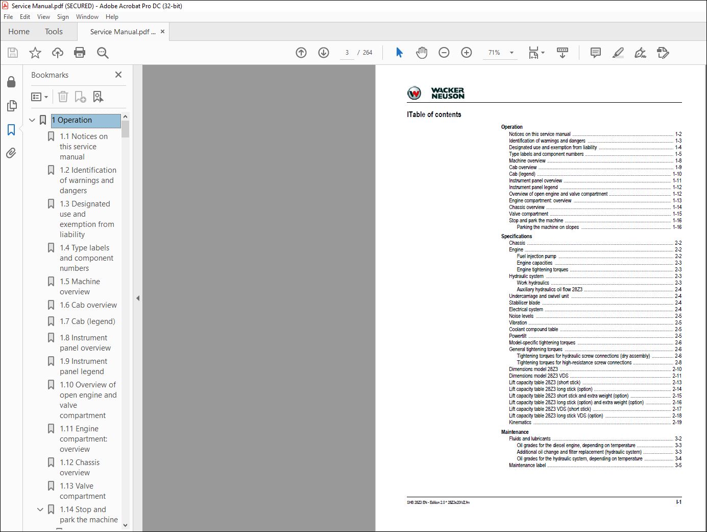
Operation
Notices on this service manual 1-2
Identification of warnings and dangers 1-3
Designated use and exemption from liability 1-4
Type labels and component numbers 1-5
Machine overview 1-8
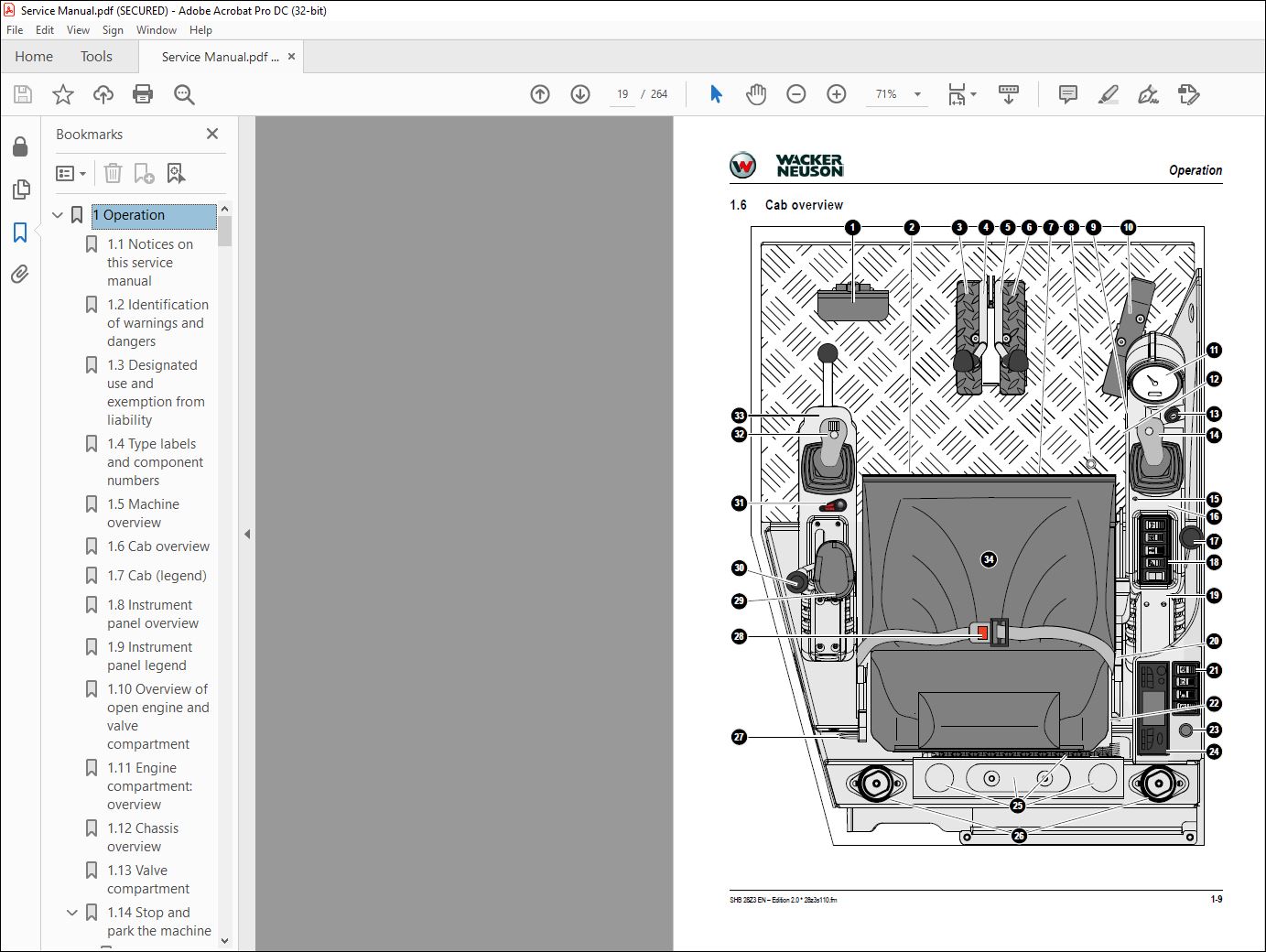
Cab overview 1-9
Cab (legend) 1-10
Instrument panel overview 1-11
Instrument panel legend 1-12
Overview of open engine and valve compartment 1-12
Engine compartment: overview 1-13
Chassis overview 1-14
Valve compartment 1-15
Stop and park the machine 1-16
Parking the machine on slopes 1-16
Specifications
Chassis 2-2
Engine 2-2
Fuel injection pump 2-2
Engine capacities 2-3
Engine tightening torques 2-3
Hydraulic system 2-3
Work hydraulics 2-3
Auxiliary hydraulics oil flow 28Z3 2-4
Undercarriage and swivel unit 2-4
Stabiliser blade 2-4
Electrical system 2-4
Noise levels 2-5
Vibration 2-5
Coolant compound table 2-5
Powertilt 2-5
Model-specific tightening torques 2-6
General tightening torques 2-6
Tightening torques for hydraulic screw connections (dry assembly) 2-6
Tightening torques for high-resistance screw connections 2-8
Dimensions model 28Z3 2-10
Dimensions model 28Z3 VDS 2-11
Lift capacity table 28Z3 (short stick) 2-13
Lift capacity table 28Z3 long stick (option) 2-14
Lift capacity table 28Z3 short stick and extra weight (option) 2-15
Lift capacity table 28Z3 long stick (option) and extra weight (option) 2-16
Lift capacity table 28Z3 VDS (short stick) 2-17
Lift capacity table 28Z3 long stick VDS (option) 2-18
Kinematics 2-19
Maintenance
Fluids and lubricants 3-2
Oil grades for the diesel engine, depending on temperature 3-3
Additional oil change and filter replacement (hydraulic system) 3-3
Oil grades for the hydraulic system, depending on temperature 3-4
Maintenance label 3-5
I-2 SHB 28Z3 EN – Edition 20 * 28Z3s20IVZfm
Explanation of symbols on the maintenance label 3-5
Maintenance plan (overview) 3-7
Service package 3-11
Introduction 3-11
Safety-relevant parts 3-11
Fuel system 3-12
Refuelling 3-13
Emptying the fuel tank 3-13
Stationary fuel pumps 3-14
Diesel fuel specification 3-14
Bleeding the fuel system 3-14
Water separator 3-15
Replacing the fuel filter 3-16
Tank for washer system 3-16
Engine lubrication system 3-17
Checking the oil level 3-17
Filling up engine oil 3-18
Changing engine oil 3-19
Replacing the engine oil filter cartridge 3-20
Engine and hydraulics cooling system 3-21
Specific safety instructions 3-21
Checking/filling up coolant 3-22
Checking the coolant level 3-22
Filling up coolant 3-23
Draining coolant 3-23
Air filter 3-24
Replacing air filter elements 3-24
Air intake 3-26
Change cab air filter 3-27
V-belt 3-28
Checking V-belt tension 3-28
Retightening the V-belt 3-29
Pressure check 3-31
General 3-31
Overview of measuring ports (up to serial number AG02712) 3-31
Overview of measuring ports (from serial number AG02713) 3-31
Checking pilot control pressure 3-32
Pressure check of variable displacement pump P1 3-33
Pressure check of variable displacement pump P2 3-34
Pressure check of gear pump P3 3-35
Secondary pressure limiting valve of the gear motor 3-36
Primary pressure limiting valves 3-36
Test report 3-37
Hydraulic system 3-41
Specific safety instructions 3-41
Checking the hydraulic oil level 3-42
Filling up hydraulic oil 3-43
Changing hydraulic oil 3-44
Monitoring the hydraulic oil return filter 3-44
Replacing the hydraulic oil filter 3-45
Draining condensation water from the hydraulic oil tank 3-45
Important information for the use of biodegradable oil 3-46
Checking hydraulic pressure lines 3-47
Pilot valve 3-48
Travelling drive 3-49
Checking the oil level and filling up oil 3-49
SHB 28Z3 EN – Edition 20 * 28Z3s20IVZfm I-3
Draining oil 3-49
Tracks 3-50
Checking track tension 3-50
Adjusting track tension 3-51
Maintenance of attachments 3-52
Lubrication points 3-52
Parking the machine 3-52
Overview of lubrication points 3-53
Lubrication points on the stabiliser blade and stabiliser blade ram 3-54
Lubrication points on the swivelling console and slewing ram 3-54
Lubrication points on the boom, bucket and stick rams 3-55
Lubrication points on the boom and stick 3-56
Lubrication point on the joint rod 3-56
Lubrication point on ball bearing race of live ring 3-57
Lubrication point of live ring teeth 3-57
Lubrication point of VDS live ring teeth 3-58
VDS lubrication points (option) 3-59
Powertilt lubrication points (option) 3-59
Lubrication points of hydraulic quickhitch (option) 3-60
Lubrication points of mechanical quickhitch (option) 3-60
Cab 3-60
Electrical system 3-61
Service and maintenance work at regular intervals 3-61
Instructions concerning specific components 3-61
Alternator 3-61
Battery 3-62
General maintenance work 3-63
Cleaning 3-63
General instructions for all areas of the machine 3-63
Inside the cab 3-63
Cleaning the seat belt 3-63
Exterior of the machine 3-64
Engine compartment 3-64
Shatter protection 3-64
Screw connections and attachments 3-64
Pivots and hinges 3-64
Preparatory work before taking out of service 3-65
Maintenance if the machine is out of service for a longer period of time 3-65
Putting into operation again 3-65
Fire extinguisher 3-66
Engine
3TNV76-NNS engine overview 4-2
Fuel system 4-4
Cooling system 4-5
Checking and adjusting valve clearance 4-6
Lapping the intake and exhaust valves 4-7
Tightening order for cylinder head bolts 4-7
Order for removing the cylinder-head bolts: 4-7
Order for mounting the cylinder-head bolts: 4-7
Checking the injection nozzles 4-8
Pressure check 4-8
Checking the nozzle jet 4-9
Injection time 4-9
Checking injection time 4-9
Setting injection time 4-11
Removing and installing the injection pump 4-12
I-4 SHB 28Z3 EN – Edition 20 * 28Z3s20IVZfm
Removing the injection pump 4-12
Fitting the injection pump 4-13
Measuring and adjusting the engine speed 4-14
Compression 4-14
Checking the coolant thermostat 4-15
Checking the thermal switch 4-15
Oil pressure switch 4-16
Checking the coolant circuit 4-16
Cleaning the cooling water channels 4-16
Coolant and fuel hoses 4-16
Crankcase vent 4-17
Replacing the glow plugs 4-17
Engine trouble 4-18
Hydraulic system
Hydraulic pump PVD-0B-23BP-8G3-5083A 5-2
Pump unit: exploded view 5-4
Pilot oil supply unit 5-5
Dismantling the hydraulic pump 5-6
Assembling the hydraulic pump 5-8
Troubleshooting on the hydraulic pump 5-12
Main valve block 5-13
Ports 5-13
Main control lines (legend) 5-14
Pump/tank lines 5-14
Main valve block diagram 5-15
Pressure limiting valves 5-16
Pump assignment 5-17
Drive counterbalancing system 5-18
Pump assignment for drive counterbalancing 5-18
Regeneration – stick section 5-19
Bucket pre-tension 5-19
Auxiliary hydraulics flow rate adjustment 5-20
Travelling drive 5-21
Function 5-22
Swivel unit 5-24
Swivel unit brake 5-25
Swivel joint 5-27
Replace the sealing rings 5-27
Swivel joint VDS (option) 5-28
Pilot valves 5-29
Joystick 5-29
Pilot valve (driving) 5-30
Changeover valve for SAE/ISO controls (option) 5-32
Proportional valve (option) 5-32
Changeover valve VDS (option) 5-33
3/2 directional valve (option) 5-33
Easy Lock valve (option) 5-33
Hydraulic oil tank service valve (option) 5-34
Breather filter 5-34
Auxiliary hydraulics connections 5-35
Troubleshooting in the hydraulic system 5-36
Hydraulics diagram (legend) 5-38
Hydraulics diagram 28Z3 5-39
Hydraulics diagram for options 28Z3 5-40
Main valve block diagram 28Z3 5-41
SHB 28Z3 EN – Edition 20 * 28Z3s20IVZfm I-5
Electrical system
Ohm’s Law (current, voltage, resistance); power 6-2
Measuring equipment, measuring methods 6-2
Cable colour coding 6-3
Relays 6-3
Use, mode of function 6-3
Socket 6-4
Electric units 6-4
Fuse box 6-4
Alternator 6-5
Starter 6-5
Switches: overview 6-6
Switch legend 6-6
Cigarette lighter 6-7
Radio and mounting/wiring for radio installation (option) 6-7
Front working light 6-8
Cab lights (option) 6-8
Rotating beacon (option) 6-9
Driving signal (option) 6-9
Wiring diagram (legend) 6-12
Wiring diagram 6-13
Engine/chassis wiring harness (legend) 6-16
Chassis/engine wiring harness 6-18
Cab wiring harness 6-19
Proportional controls wiring harness (option) 6-20
Engine speed control wiring harness (option) 6-21
Driving signal wiring harness (option) 6-22
Hydraulic quickhitch wiring harness (option) 6-23
Battery lead 6-24
Options
Counterweight 7-2
Specifications 7-2
Long stick 7-2
Specifications 7-2
Automatic engine speed setting 7-3
Installation 7-4
Grab pipework 7-5
Attachments 7-5
3rd control circuit/PowerTilt ports 7-6
Safe load indicator 7-7
Safe load indicator DE (from serial no AG04828) (safety valves for boom) 7-8
Safe load indicator DE (serial nos AG02444 to AG04827) (safety valves for boom)
7-9
Safe load indicator DE (up to serial no AG02443) 7-10
Function 7-10
Wiring diagram 7-11
Setting the pressure switch 7-11
Safe load indicator FR (from serial no AG04828) (safety valves for boom, stick and stabiliser
blade) 7-12
Safe load indicator FR (serial nos AG02444 to AG04827) (safety valves for boom,
stick and stabiliser blade)
7-13
Safe load indicator FR (up to serial no AG02443) 7-14
Function 7-14
Diagram (from serial no AG04828) 7-15
Diagram (serial nos AG02444 to AG04827) 7-16
I-6 SHB 28Z3 EN – Edition 20 * 28Z3s20IVZfm
Diagram (up to serial no AG02443) 7-16
Setting the pressure switch 7-17
Hose burst valve safety feature 7-18
Mechanical quickhitch 7-19
Hydraulic quickhitch (Easy Lock) 7-20
3rd control circuit 7-20
Function 7-20
Diagram 7-20
Drive interlock (antitheft protection) 7-21
Position 7-21
Disabling the drive interlock 7-21
Enabling the drive interlock 7-21
Programming 7-21
Proportional controls 7-23
Function 7-23
Ports 7-24
Measures to be taken in case of malfunctions 7-24
Left-hand control lever 7-24
Boom swivel controls 7-25
Auxiliary hydraulics 7-25
Hammer operation 7-25
Adjusting control response 7-26
Characteristic curves – status indicator 7-26
Wiring harness 7-27
Control unit connector assignment 7-27
Measures to be taken in case of malfunctions 7-28
Diagnosis display 7-28
Engine oil service valve 7-29
Function 7-29
PowerTilt PTS06
General instructions 8-2
General safety instructions 8-2
Checking the product 8-3
Internal decompression valve 8-3
Testing the hydraulic system of the machine 8-3
Specifications/requirements 8-4
Tools 8-5
Making a tool VI for removing the seals 8-6
Separating the bucket or equipment from the PowerTilt swivel device 8-6
Separating the PowerTilt swivel device from the machine 8-6
Exploded views PTS06 8-7
PTS06 components 8-7
Sealing kit A and bearing kit B PTS06 (overview) 8-8
Assembly drawing 8-9
Removing the standard journal coupling 8-10
Removing the end cap, securing ring and internal decompression valve 8-12
Removing the shaft 8-13
Removing the piston tube body 8-14
Removing the seals (kit A), shaft bearings and pressure discs (kit B) 8-15
Checking components and dead centre marks 8-16
Trial assembly 8-17
Installing the seals (kit A), shaft bearings and pressure discs (kit B) 8-17
Installing the end-cap seals and bearings 8-18
Installing the piston seals and bearings 8-19
SHB 28Z3 EN – Edition 20 * 28Z3s20IVZfm I-7
Fitting the shaft seal and the bearing 8-20
Installing the piston tube 8-21
Installing the shaft 8-22
Installing the end cap and the securing ring 8-23
Installing the internal decompression valve 8-24
Installing the standard journal coupling 8-24
Lubrication and tests 8-27
Lubrication 8-27
Test for internal leaks 8-27
Testing the internal decompression valve 8-28
Securing the PowerTilt swivel device on the machine 8-29
Fitting a bucket or equipment onto the PowerTilt swivel device 8-29
Troubleshooting 8-30
Adjusting the play on the PowerTilt 8-31
Checking the circumferential play 8-31
VIDEO PREVIEW OF THE MANUAL:
PLEASE NOTE:
- This is the same manual used by the dealers to diagnose and troubleshoot your vehicle
- You will be directed to the download page as soon as the purchase is completed. The whole payment and downloading process will take anywhere between 2-5 minutes
- Need any other service / repair / parts manual, please feel free to contact [email protected] . We still have 50,000 manuals unlisted
S.M


