Wacker Neuson 1501 Dumper Service Repair Manual 1000144667 PDF
$26.95
WACKER NEUSON 1501 DUMPER SERVICE MANUAL 1000144667 – PDF DOWNLOAD
Description
WACKER NEUSON 1501 DUMPER SERVICE MANUAL 1000144667 – PDF DOWNLOAD
FILE DETAILS:
WACKER NEUSON 1501 DUMPER SERVICE MANUAL 1000144667 – PDF DOWNLOAD
Language : English
Pages : 174
Downloadable : Yes
File Type : PDF
IMAGES PREVIEW OF THE MANUAL:
TABLE OF CONTENTS:
WACKER NEUSON 1501 DUMPER SERVICE MANUAL 1000144667 – PDF DOWNLOAD
Operation
Important information on this service manual 1-1
Identification of warnings and dangers 1-2
Designated use and exemption from liability 1-3
Type labels and component numbers 1-4
Machine overview 1501 D 1-6
Machine overview 1501 1-7
Machine overview 1501S 1-8
Operating equipment: overview 1-9
Operating equipment: legend 1-10
Maintenance prop, model 1501 1-10
Maintenance prop, model 1501S 1-11
Centre pivot prop, model 1501/1501S 1-12
Specifications
Chassis 2-1
Engine 2-1
Engine capacities 2-2
Engine tightening torques 2-2
Fuel injection pump 2-2
Travelling drive 2-3
Brakes 2-3
Steering system 2-3
Work hydraulics 2-3
Loader unit 2-3
Drive specifications 2-4
Vibration 2-4
Electric system (up to AC000335) 2-5
Fuse box 2-5
Relays 2-5
Electric system (from AB150001H/150002D) 2-6
Fuse box 2-6
Relays 2-6
Tyres 2-7
Noise levels 2-7
Coolant compound table 2-7
General tightening torques 2-8
Tightening torques for hydraulic screw connections (dry assembly) 2-8
Tightening torques for high-resistance screw connections 2-10
Tightening moments for Nordlock lock washers 2-11
Dimensions model 1501 2-12
Dimensions model 1501S 2-13
Maintenance
Fluids and lubricants 3-3
Maintenance plan (overview) 3-5
Service package 3-8
Introduction 3-8
Fuel system 3-9
Specific safety instructions 3-9
Refuelling 3-9
Stationary fuel pumps 3-10
Diesel fuel specification 3-10
Bleeding the fuel system 3-10
Fuel prefilter with water separator 3-11
Replacing the fuel filter 3-12
Table of contents
I-2 SERV-HB 1501 EN – Edition 1 1 * 1501s11IVZ fm
Table of contents
Engine lubrication system 3-13
Checking the oil level 3-13
Filling up engine oil 3-14
Changing engine oil 3-15
Replacing the engine oil filter cartridge 3-16
Cooling system 3-17
Specific safety instructions 3-17
Checking/filling up coolant 3-18
Draining coolant 3-19
Air filter 3-20
Weekly check of air filter contamination 3-20
Replacing the filter 3-21
V-belt 3-22
Checking V-belt tension 3-22
Retightening the V-belt 3-23
Hydraulic system 3-24
Specific safety instructions 3-24
Checking the hydraulic oil level 3-25
Filling up hydraulic oil 3-25
Changing hydraulic oil 3-26
Monitoring the hydraulic oil reflux filter 3-26
Replacing the hydraulic oil reflux filter 3-26
Checking hydraulic pressure lines 3-27
Lubrication points 1501: overview 3-28
Lubrication points 1501S: overview 3-29
Tyre maintenance 3-30
Checks once a day 3-30
Checks once a week 3-30
Changing wheels 3-31
Removing the wheels 3-31
Fitting the wheels 3-31
Electric system 3-32
Specific safety instructions 3-32
Service and maintenance work at regular intervals 3-32
Instructions concerning specific components 3-33
Alternator 3-33
Battery 3-34
Battery master switch 3-35
General maintenance work 3-36
Cleaning 3-36
General instructions for all areas of the machine 3-36
Screw connections and attachments 3-36
Pivots and hinges 3-36
Engine
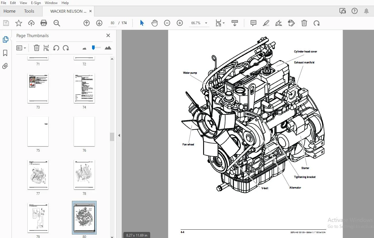
Engine overview 3TNE74 (up to AC000335) 4-2
Fuel system (up to AC000335) 4-4
Engine overview 3TNV76-XNSV (from AB100001H) 4-5
Fuel system (from AB100001H) 4-7
Checking and adjusting valve tip clearance 4-8
Tightening order for cylinder head bolts 4-9
Checking the injection nozzles 4-10
Pressure check 4-10
Checking the nozzle jet 4-10
Fuel injection time (up to AC000335) 4-11
Fuel injection time (from AB100001H) 4-12
Adjusting engine revs 4-13
SERV-HB 1501 EN – Edition 1 1 * 1501s11IVZ fm I-3
Table of contents
Compression 4-13
Checking the coolant thermostat 4-13
Checking the thermal switch 4-14
Oil pressure switch 4-14
Checking the coolant circuit 4-15
Engine trouble 4-15
Travelling drive
Variable displacement pump A10VG45DA 5-1
Variable displacement pump: diagram 5-3
Variable displacement pump: design 5-4
Travelling drive: overview 5-5
Connecting plate with valves 5-6
Rear hydraulic motor 5-7
Front hydraulic motor 5-8
Hydraulic motor: overview 5-9
Travelling drive: overview 5-11
Towing and transporting the machine 5-12
Safety instructions 5-12
Towing 5-12
Opening the high-pressure circuit 5-12
Releasing the hydraulic parking brake 5-13
Test instruction 5-14
Pilot pressure check 5-14
High pressure check 5-15
Brakes
Brake circuit up to serial no AC000241 6-1
Brake diagram 6-2
Brake circuit from serial no AC000242 6-3
Brake diagram 6-4
Steering system
Steering circuit 7-1
Steering unit: diagram 7-2
Function 7-2
Steering unit connections 7-3
Steering unit: overview 7-4
Priority valve: overview 7-4
Priority valve: legend 7-4
Steering unit 7-5
Steering unit: legend 7-6
Hydraulic system
Control valve connections: overview 8-1
Test instructions 8-2
Check: work pump pressure 8-2
1501 diagram up to serial no AC000241 8-3
1501 diagram up to serial no AC000241: legend 8-4
1501 diagram from serial no AB150001H/AB150002D 8-5
1501 diagram from serial no AB150001H/AB150002D: legend 8-6
1501S diagram up to serial no AC000241 8-7
1501S diagram up to serial no AC000241: legend 8-8
1501S diagram from serial no AC000242 8-9
1501S diagram from serial no AC000242: legend 8-10
Hydraulics diagram A3 1501 up to serial no AC000241 8-11
Hydraulics diagram A3 1501 from serial no AB150001H/AB150002D 8-12
Hydraulics diagram A3 1501S up to serial no AC000241 8-13
Hydraulics diagram A3 1501S from serial no AC000242 8-14
Ohm’s Law (current, voltage, resistance); power 9-1
Measuring equipment, measuring methods 9-1
Relays 9-2
Use, mode of function 9-2
Electric components 9-3
Fuse box in instrument panel (up to AC000335) 9-3
Relays 9-3
Instrument panel: overview 9-4
Fuse box on instrument panel (from AB150001H/AB150001D) 9-5
Relays 9-5
Instrument panel (from AB150001H/AB150002D): overview 9-6
Wiring diagram up to serial no AC000241: legend 9-8
Wiring diagram version 1 A4 up to serial no AC000241 9-9
Wiring diagram from serial no AC000242 to AC000335: legend 9-10
Wiring diagram version 1 A4 from serial no AC000242 to AC000335 9-11
Wiring diagram from serial no AB150001H/AB150002D: legend 9-12
Wiring diagram version 1 A4 from serial no AB150001H/AB15002D 9-13
Main wiring harness from AB150001H/AB150002D: legend 9-14
Main wiring harness from AB150001H/AB150002D 9-15
Engine wiring harness from AB150001H/AB150002D: legend 9-16
Engine wiring harness from AB150001H/AB150002D 9-17
Wiring diagram A3 up to serial no AC000241: legend 9-20
Wiring diagram A3 up to serial no AC000241 9-21
Wiring diagram A3 from serial no AC000242 to AC000335: legend 9-22
Wiring diagram A3 from serial no AC000242 to AC000335 9-23
Wiring diagram A3 from serial no AB150001H/AB150002D: legend 9-24
Wiring diagram A3 from serial no AB150001H/AB150002D 9-25
Main wiring harness from AB150001H/AB150002D: legend 9-26
Main wiring harness from AB150001H/AB150002D 9-27
Engine wiring harness from AB150001H/AB150002D: legend 9-28
Engine wiring harness from AB150001H/AB150002D 9-29
DESCRIPTION:
WACKER NEUSON 1501 DUMPER SERVICE MANUAL 1000144667 – PDF DOWNLOAD
This service manual contains important information on how to service your machine safely, correctly and economically. Therefore, it aims not only at new staff, but it also serves as a reference for experienced users. It helps to avoid dangerous situations and reduce repair costs and downtimes. Furthermore, the reliability and the service life of the machine will be increased by following the instructions in the service manual.
Careful and prudent working is the best way to avoid accidents!
Operational safety and readiness of the machine do not only depend on your skill, but also on maintenance and service of the machine.
Insist on using original spare parts when carrying out maintenance and repair work.
This ensures operational safety and readiness of your machine, and maintains its value.
Your Neuson dealer will be pleased to answer any further questions regarding the machine or the service manual.
S.S 02/01/2025