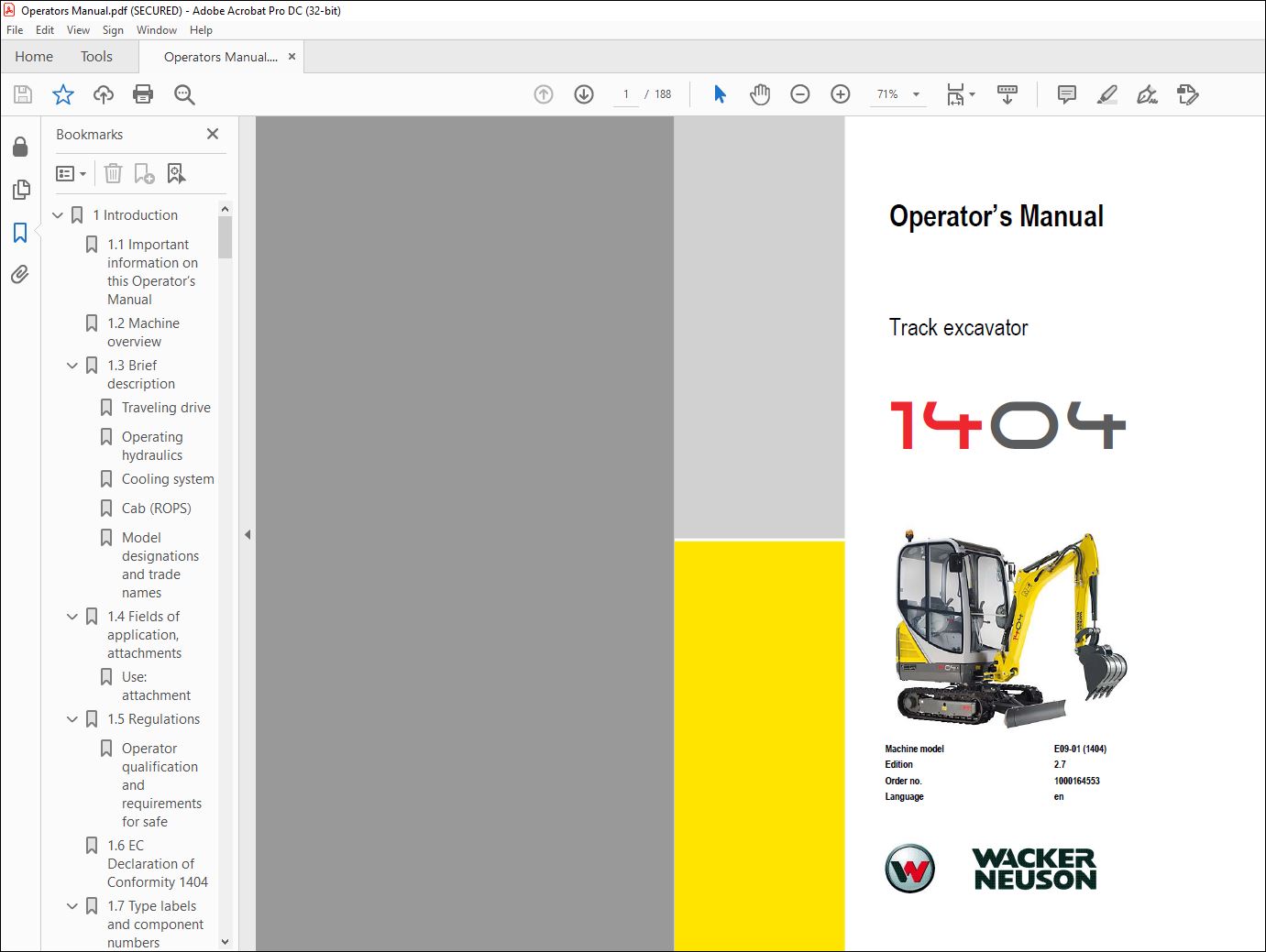
Wacker Neuson 1404 TRACKS EXCAVATORS Operator’s Manual – PDF DOWNLOAD
IMAGES PREVIEW OF THE MANUAL:

DESCRIPTION:
Wacker Neuson 1404 TRACKS EXCAVATORS Operator’s Manual – PDF DOWNLOAD
1 Introduction
1.1 Important information on this Operator’s Manual
- The Operator’s Manual is stored in the storage bin at the rear of the seat. This Operator’s Manual contains important information on how to work safely, correctly, and economically with the machine. Therefore, it aims not only at new personnel, but it also serves as a reference for experienced personnel.
- It helps to avoid hazardous situations and reduce repair costs and downtimes. Furthermore, the reliability and the service life of the machine will be increased by following the instructions in the Operator’s Manual. This is why the Operator’s Manual must always be kept at hand in the machine.
- Your own safety, as well as the safety of others, depends to a great extent on how the machine is moved and operated. Carefully read the Operator’s Manual before putting the machine into operation. This Operator’s Manual will help to familiarize yourself more easily with the machine, thereby enabling you to use it more safely and efficiently.
- Follow chapter “Safety Instructions” in particular. As a rule, keep the following in mind: Careful and prudent working is the best way to avoid accidents! Operational safety and readiness of the machine do not only depend on your skill, but also on maintenance and servicing of the machine. This is why regular maintenance and servicing is absolutely necessary.
• Special equipment and superstructures are not described in this Operator’s Manual.
• We reserve the right to improve the technical standard of our machines without adapting the Operator’s Manual.
• Modifying Wacker Neuson products and fitting them with additional equipment and attachments not included in our delivery program requires Wacker Neuson’s written authorization, otherwise warranty and product liability for possible damage caused bythese modifications shall not be applicable.
• Subject to modifications and printing errors. Your Wacker Neuson dealer will be pleased to answer any further questions regarding themachine or the Operator’s Manual
TABLE OF CONTENTS:
Wacker Neuson 1404 TRACKS EXCAVATORS Operator’s Manual – PDF DOWNLOAD
Introduction
Important information on this Operator’s Manual 1-1
Machine overview 1-2
Brief description 1-3
Traveling drive 1-3
Operating hydraulics 1-3
Cooling system 1-3
Cab (ROPS) 1-3
Model designations and trade names 1-4
Fields of application, attachments 1-4
Use: attachment 1-4
Regulations 1-5
Operator qualification and requirements for safe operation 1-5
EC Declaration of Conformity 1404 1-6
Type labels and component numbers 1-7
Overview of adhesive labels 1-10
Overview of safety labels 1-13
Fire extinguisher 1-18
Safety instructions
Identification of warnings and dangers 2-1
Warranty 2-1
Disposal 2-1
Designated use and exemption from liability 2-2
General conduct and safety instructions 2-3
Organizational measures 2-3
Selection and qualification of personnel, basic responsibilities 2-4
Safety instructions regarding operation 2-5
Normal operation 2-5
Cabin/canopy 2-7
Explanation of abbreviations 2-7
Checks when reversing the machine 2-7
Applications with lifting gear 2-7
Trailers and attachments 2-8
Transportation 2-8
Working in the area of underground electric lines 2-8
Working near overhead electric lines 2-9
Safety instructions for maintenance 2-9
Warning of special hazards 2-11
Electrical energy 2-11
Gas, dust, steam, smoke 2-11
Hydraulic system 2-11
Noise 2-12
Oil, grease and other chemical substances 2-12
Battery 2-12
Air intake 2-12
Tracks 2-12
Hammer operation 2-13
Safety instructions 2-13
Working with a hammer 2-13
Operation
Table of contents
1-2 BA 1404 en – Edition 27 * * Ba1404en2_7IVZfm
Table of contents
Cabin overview 3-2
Cabin overview (legend) 3-3
Instrument panel overview 3-4
Instrument panel overview (legend) 3-5
Putting into operation 3-6
Safety instructions 3-6
Putting into operation for the first time 3-6
Running-in period 3-6
Check lists 3-7
Start-up checklist 3-7
Operation checklist 3-8
Parking checklist 3-8
Driving the excavator 3-9
Preheating start switch (overview) 3-9
Throttle lever overview 3-9
Speed range selection 3-10
Indicator lights and warning lights (overview) 3-10
Before starting the engine 3-13
Starting the engine: general 3-13
Procedure 3-13
Starting with the drive interlock (option) 3-14
Starting with the drive interlock – internal transponder (option) (from serial number
AG00673) 3-14
Starting at low temperatures 3-16
When the engine has started 3-16
Engine warm-up 3-16
Jump-starting the engine (supply battery) 3-17
Starting machine travel 3-18
Drive levers 3-18
Hydraulic brake 3-19
Stabilizer blade as a parking brake 3-19
Operating temperature range 3-19
Machine travel on slopes 3-20
Stabilizer blade operation 3-22
Changing the width of the stabilizer blade 3-24
Telescopic travel gear (option) 3-25
Retract or extend the telescopic travel gear 3-26
Upper carriage lock 3-28
Parking the machine 3-28
Parking the machine on slopes 3-29
Light system 3-30
Roof lights (option) 3-30
Interior light 3-30
Rotating beacon (option) 3-31
Cab heating and ventilation 3-31
Heating adjustment 3-32
Washer system 3-32
Tank for washer system 3-32
Seat adjustment 3-33
Weight adjustment 3-33
Horizontal adjustment 3-34
Backrest adjustment 3-34
Seat belt 3-34
Retracting belt (option) 3-36
Emergency exit (with cab option) 3-37
Front window (with cab option) (up to serial number AF05320) 3-38
Front window (from serial number AG02423) 3-39
BA 1404 en – Edition 27 * Ba1404en2_7IVZfm 1-3
Table of contents
Opening/closing the front window 3-39
Opening/closing the lower front window 3-40
Door (with cab option) 3-40
Cab/canopy entry and exit 3-42
Safety instructions regarding entry and exit 3-42
Engine cover 3-43
Battery master switch 3-44
Mirrors (option) 3-45
Towing the track excavator 3-47
Towing 3-47
Crane-lifting the machine 3-48
Loading and transporting the machine 3-52
Tying down the machine 3-53
Protective structures 3-54
Definition of the term “Protective Structure” 3-54
Mechanical integrity 3-54
Definition of FOPS levels 3-54
Responsibility for machine equipped with protective structures 3-54
Protective FOPS structure/small screen – category I (option from serial no
AG02423) 3-55
Protective FOPS structure/large screen – category II (option) 3-57
3-58
Shatter protection for canopy (option) 3-59
Travel signal (option) 3-61
Machine operation 3-62
General safety instructions 3-62
Control levers/ISO controls: overview 3-63
Control lever on the left 3-63
Boom swivel controls 3-63
Auxiliary hydraulics 3-64
Right-hand control lever 3-65
Emergency lowering 3-65
Rotating the upper carriage 3-66
Swivel unit brake 3-66
Changeover valve for SAE/ISO controls (option) 3-67
Control lever on the left 3-67
Control lever on the right 3-67
Directional valve position 3-68
Directional valve 3-68
Release the pressure in the operating hydraulics 3-69
Releasing pressure 3-69
Re-equipping attachments 3-70
Specific safety instructions 3-70
Removing a bucket 3-70
Installing a bucket 3-71
Quickhitch (option) 3-71
Hydraulic quickhitch – Easy Lock (option) 3-72
Picking up an attachment 3-73
Setting down an attachment 3-75
Connections for auxiliary hydraulics 3-76
Grab couplings 3-77
Attachments 3-77
Maintenance of attachments 3-77
Working with the standard bucket 3-77
General information regarding work operation 3-78
Inadmissible work procedures 3-78
Excavator work position 3-80
1-4 BA 1404 en – Edition 27 * * Ba1404en2_7IVZfm
Table of contents
Bucket position when digging 3-80
Excavating trenches 3-80
Loading 3-81
Grading 3-81
Excavating trenches laterally 3-81
Grading 3-83
Grading 3-83
Working alongside trenches 3-84
Malfunctions
Engine trouble 4-1
Maintenance
Introduction 5-1
Fuel system 5-2
Specific safety instructions 5-2
Refueling 5-2
Draining the fuel 5-3
Stationary fuel pumps 5-3
Bleeding the fuel system 5-4
Fuel prefilter with water separator 5-5
Engine lubrication system 5-6
Checking the oil level 5-6
Adding engine oil 5-7
Engine cooling system 5-8
Specific safety instructions 5-8
Checking the coolant level/adding coolant 5-9
Air filter (up to serial number AG03170) 5-11
Air intake 5-11
Replacing the filter 5-12
Air filter (from serial no AG03171) 5-13
Air intake 5-13
Replacing air filter elements 5-14
Replacing the cabin air filter 5-16
V-belt 5-17
Checking V-belt tension 5-17
Tightening the V-belt (alternator) 5-18
Checking the V-belt of the alternator 5-19
Hydraulic system 5-20
Important information on the hydraulic system 5-20
Checking the hydraulic oil level 5-21
Adding hydraulic oil 5-21
Important notices on the use of biodegradable oil 5-22
Checking hydraulic pressure lines 5-23
Overview of lubrication points 5-24
Parking the machine 5-25
Lubricating the ball bearing race of the live ring 5-25
Lubricating the teeth of the live ring 5-26
Lubrication points of hydraulic quickhitch (option) 5-26
Tracks 5-27
Checking track tension 5-27
Setting the tracks 5-28
Traveling drive 5-29
Maintenance of attachments 5-29
Electrical system 5-29
Specific safety instructions 5-29
Servicing and maintenance at regular intervals 5-29
Instructions concerning specific components 5-29
BA 1404 en – Edition 27 * Ba1404en2_7IVZfm 1-5
Table of contents
Alternator 5-30
Battery 5-31
General maintenance 5-32
Cleaning 5-32
General instructions for all areas of the machine 5-32
Inside the cabin 5-33
Exterior of the machine 5-33
Engine compartment 5-33
Threaded fittings and attachments 5-33
Pivots and hinges 5-33
Preparatory work before taking out of service 5-34
Maintenance when out of service for a longer period of time 5-34
Putting into operation again 5-34
Fluids and lubricants 5-35
Additional oil change and filter replacement (hydraulic system) 5-36
Maintenance plan (overview) 5-38
Maintenance label 5-42
Explanation of symbols on the maintenance label 5-42
Technical data
Chassis 6-1
Engine 6-1
Hydraulic system 6-2
Travel gear and swivel unit 6-3
Stabilizer blade 6-3
Operating hydraulics 6-3
Electrical system 6-4
Fuses on control lever base on the left 6-4
Main fuse and relays in the engine compartment 6-4
Noise levels 6-5
Vibration 6-5
Coolantcompound table 6-7
Dimensions 6-8
Lift capacity tables 6-10
Safety instructions – lift capacity tables 6-10
Lift capacity table (standard chassis and canopy) 6-11
Lift capacity table with long stick (Standard chassis and canopy) (option) 6-12
Lift capacity table with cabin (option) and telescopic undercarriage (option) 6-13
Lift capacity table with cabin (option), long dipper arm (option) and telescopic undercarriage
(option)
VIDEO PREVIEW OF THE MANUAL:
PLEASE NOTE:
- This is the SAME exact manual used by your dealers to fix your vehicle.
- The same can be yours in the next 2-3 mins as you will be directed to the download page immediately after paying for the manual.
- Any queries / doubts regarding your purchase, please feel free to contact [email protected]
S.M