Unicarriers Forklift TX30M TX35M TX40M Controller Service Manual PDF
$28.95
Unicarriers Forklift TX30M TX35M TX40M Controller Service Manual – PDF DOWNLOAD
TX30M AUB25-00012-09999
TX35M AUB26-00012-09999
TX40M AUB26-50012-59999
Description
Unicarriers Forklift TX30M TX35M TX40M Controller Service Manual – PDF DOWNLOAD
FILE DETAILS:
Unicarriers Forklift TX30M TX35M TX40M Controller Service Manual – PDF DOWNLOAD
Language : English
Pages : 311
Downloadable : Yes
File Type : PDF
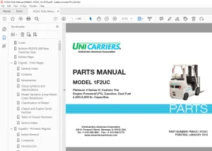
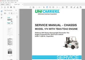
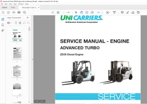
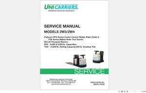
IMAGES PREVIEW OF THE MANUAL:
TABLE OF CONTENTS:
Unicarriers Forklift TX30M TX35M TX40M Controller Service Manual – PDF DOWNLOAD
TX30M AUB25-00012-09999
TX35M AUB26-00012-09999
TX40M AUB26-50012-59999
FRONT COVER 1
FOREWORD 2
1 Safety 3
2 LOCKOUT/TAGOUT 5
3 How to Use This Manual 6
3 1 Lift Truck Model 6
4 Symbols and Abbreviations 7
5 Units 7
Chapter 1 CONTROLLER 8
Chapter 2 TROUBLESHOOTING FOR CONTROL CIRCUITS 9
Chapter 3 MOTOR 10
Chapter 4 HOW TO READ CIRCUIT DIAGRAMS 11
Chapter 5 CIRCUIT DIAGRAM 11
Chapter 1 CONTROLLER 12
1 Controller System 12
1 1 System Layout 12
1 2 Controller Area Network (CAN) 14
1 3 Outline of Logic Unit 15
1 4 Outline of Inverter 18
1 5 Outline of EPS Controller 19
2 Traction Controller Feature 20
2 1 Modification of Traction Characteristics 20
2 2 Anti-rollback 20
2 3 Boost 21
2 4 Limitation of Maximum Travel Speed 21
2 5 Controlled Cornering Speed 22
2 6 Miscellaneous Features for Traction 22
3 Lifting Controller Feature 23
3 1 Setting and Limitation of Lift Work Speed 23
3 2 Lift Stop 23
4 Other Feature 24
4 1 Operator Presence System (OPS) Feature 24
4 2 Display Function 26
4 3 Parking Brake Warning Icon 27
4 4 BDI (Battery Discharge Indicator) Display Features 27
4 5 Miscellaneous Features 27
4 6 Hour Meter 28
5 Setup Option 29
5 1 Outline 29
5 2 Details of Setup Options (Group-1) 30
5 3 Details of Setup Options (Group-2) 34
5 4 Details of Setup Options (Group-3) 39
5 5 Setup Options (Group 1) 43
5 6 Setup Options (Group 2) 44
5 7 Setup Options (Group 3) 46
6 Diagnostics 47
6 1 Outline 47
6 2 Operation Procedure 47
6 3 Self-Diagnostics 49
6 4 Power Steering Diagnostics 50
6 5 Run Time Diagnostics 52
6 6 Fail-Safe Restriction List 59
7 Removal and Installation 61
7 1 Inverter Discharging Procedure 61
7 2 Replacing Inverter 62
7 3 Replacing DSP (Digital Signal Processor) Card 63
7 4 Replacing Logic Unit 65
7 5 Replacing EPS Controller 66
7 6 Replacing Logic Card 67
7 7 Replacing Power Supply Card 68
7 8 Replacing FC Armrest (FC Model Only) 69
7 9 Replacing Output Unit (FC Model Only) 70
8 Basic Check 71
8 1 Testing Tools 71
8 2 Measurement of Card Voltage 71
8 3 Checking Contactor Coil 77
8 4 Checking Contactor Tips 77
8 5 Checking Inverter 78
8 6 Regeneration Check 78
9 AC Motor System Basics 79
9 1 Feature of AC motor 79
9 2 Speed Control of Induction Motors 79
9 3 Inverter 80
Chapter 2 TROUBLESHOOTING FOR CONTROL CIRCUITS 81
1 General Information 81
1 1 Before Replacing Devices 81
1 2 Connection of the Service Tool 81
1 3 How to Clean Harness Connectors and System Components 82
2 List of Diagnostic Codes 83
3 Troubleshooting 84
3 1 Traction Motor R H ,Overheating (E0) 84
3 2 Traction Motor L H ,Overheating (E1) 88
3 3 Pump Motor, Overheating (E2) 92
3 4 Traction Inverter R H , Overheating (E5) 95
3 5 Traction Inverter L H , Overheating (E6) 98
3 6 Pump Inverter, Overheating (E7) 101
3 7 PS Controller, Overheating (E9) 104
3 8 Traction Motor Current Sensor R H , Fault (14) 107
3 9 Traction Motor R H , Over-current (15) 109
3 10 Traction Motor R H , Stall Timer (16) 113
3 11 Traction Motor Current Sensor L H , Fault (24) 116
3 12 Traction Motor L H , Over-current (25) 118
3 13 Traction Motor L H , Stall Timer (26) 122
3 14 Pump Motor Current Sensor Fault (34) 125
3 15 Pump Motor Over-current (35) 127
3 16 Line Contactor Fault (40) 130
3 17 Steering Contactor Fault (41) 133
3 18 Traction Motor R H , Open (45) 136
3 19 Traction Motor L H , Open (46) 139
3 20 Pump Motor Open (47) 142
3 21 PS Motor Open (49) 145
3 22 Tire Angle Sensor Fault (50) 148
3 23 Accelerator Sensor Fault (51) 151
3 24 Traction Motor R H , Pulse Input Fault (52) 154
3 25 Traction Motor L H , Pulse Input Fault (53) 157
3 26 FC Lever Fault (54) 160
3 27 Output Unit Solenoid Fault (55) 162
3 28 Output Unit Solenoid Current Leak (56) 165
3 29 FNR Lever or Accelerator, Faulty Setting (E) 167
3 30 Seat Switch, Faulty Setting for Traction ((E)) 170
3 31 Lift Lever, Faulty Setting (H1) 173
3 32 Tilt Lever, Faulty Setting (H2) 176
3 33 Attachment 1 Lever, Faulty Setting (H3) 179
3 34 Attachment 2 Lever, Faulty Setting (H4) 182
3 35 Seat Switch, Faulty Setting for Hydraulic ((L)) 185
3 36 FNR Lever Fault (EE) 188
3 37 Display Communication Fault (60) 190
3 38 Logic Card Initialize Failure (61) 193
3 39 Logics Fault (62) 194
3 40 Traction Inverter R H , Fault (63) 195
3 41 Traction Inverter L H , Fault (64) 199
3 42 Pump Inverter Fault (65) 203
3 43 FC Armrest (67) 207
3 44 Output Unit Fault (68) 208
3 45 EPS Controller Fault (71) 210
3 46 Contactor Coil Fault (72) 214
3 47 Hydraulic Lock Solenoid Fault (74) 216
3 48 Parking Brake Fault (75) 218
3 49 OPS Buzzer Fault (76) 220
3 50 Battery Voltage Too Low (78) 222
3 51 Battery Voltage Too High (79) 224
3 52 Battery Consumption Too Much (Lo) 226
3 53 Tilt Angle Sensor Fault (80) 228
3 54 Load Sensor Fault (81) 230
3 55 Handle Sensor Fault (82) 232
3 56 PS Motor Current Sensor Fault (A4) 234
3 57 PS Motor Over-current (A5) 236
3 58 PS Handle Brake Fault (A7) 238
3 59 Battery Side Way Exchange Interlock (A8) 240
3 60 Parking brake warning (A9) 242
3 61 Battery Consumption Much 244
3 62 Brake Oil, Low Level 246
3 63 RTC Battery Low 248
Chapter 3 MOTOR 249
1 Motor Installation Positions 249
2 Specifications 250
3 Structures 251
3 1 Traction Motor 251
3 2 Pump Motor 252
3 3 EPS Motor 253
4 Removing Transfer Assemblies, Traction Motors 254
5 Disassembling Traction Motor 255
5 1 Disassembly Sequence 255
6 Inspecting Traction Motor 256
6 1 Inspecting Rotor 256
6 2 Inspecting Motor 256
6 3 Inspection of Insulation 257
7 Assembling Traction Motor 258
7 1 Assembly Sequence 258
8 Removing Pump Motor 259
8 1 Suggestions for Removal 259
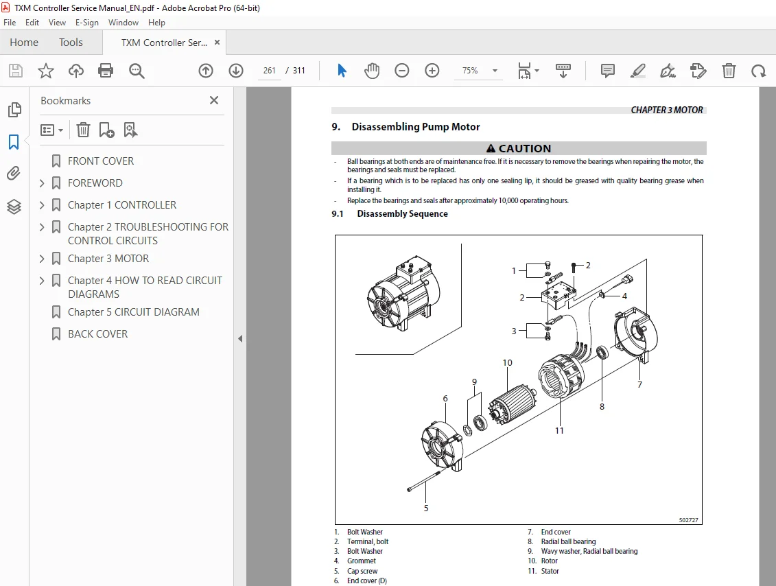
9 Disassembling Pump Motor 261
9 1 Disassembly Sequence 261
10 Inspecting Pump Motor 262
10 1 Inspecting Rotor 262
10 2 Inspecting Motor 262
10 3 Inspection of Insulation 262
11 Assembling Pump Motor 263
11 1 Assembly Sequence 263
12 Tightening of High-power Cable Terminals 264
13 Removing EPS Motor 265
13 1 Suggestions for Removal 265
14 Disassembling EPS Motor 265
15 Inspecting EPS Motor 266
15 1 Inspecting Armature 266
15 2 Inspecting Motor 268
15 3 Inspecting Oil Seal and Permanent Magnet 269
16 Inspecting EPS Motor 270
16 1 Brush 270
17 Troubleshooting 271
Chapter 4 HOW TO READ CIRCUIT DIAGRAMS 272
1 Description of Circuit Diagrams 272
1 1 Schematic Diagram 272
1 2 Connector Diagrams 272
2 How to Read Circuit Diagrams 273
2 1 Symbols 274
2 2 Sheet Symbol 277
2 3 Connecting Lines 278
2 4 Equipment 279
2 5 Relay Contactor and Coil 280
2 6 Connectors 280
2 7 Indication of Connecting Line 281
2 8 Indication of GND (Earth) 281
2 9 Indication of Another Specification 282
3 How to Read Connector Diagrams 283
Chapter 5 CIRCUIT DIAGRAM 285
BACK COVER 311
S.V 23/01/2025