Toyota Forklift 7SM10 7SM12 7SM12S Service Manual – PDF DOWNLOAD
$27.95
Toyota Forklift 7SM10 7SM12 7SM12S Service Manual – PDF DOWNLOAD
Description
Toyota Forklift 7SM10 7SM12 7SM12S Service Manual – PDF DOWNLOAD
FILE DETAILS:
Toyota Forklift 7SM10 7SM12 7SM12S Service Manual – PDF DOWNLOAD
Language : English
Pages : 182
Downloadable : Yes
File Type : PDF
IMAGES PREVIEW OF THE MANUAL:

TABLE OF CONTENTS:
Toyota Forklift 7SM10 7SM12 7SM12S Service Manual – PDF DOWNLOAD
1- Table of contents 3
2- General product information – M2 9
21 Intended application of the truck 9
22 Prohibited application of the truck 9
23 Truck data 10
24 Truck dimensions 11
25 Identification plate 12
26 Capacity plate 13
27 Modification plate 13
28 Main components 14
29 Warning and information plates and symbols 16
3- Technical data – M4 19
4- Introduction Maintenance – P1 23
41 Safety regulations with maintenance work 23
42 Cleaning and washing 24
421 External cleaning 25
422 Cleaning the motor compartment 25
423 Electrical components 25
43 Safe lifting 26
5- Preventive maintenance – P2 27
51 Maintenance schedule 27
52 Lubrication schedule 32
6- Oil and grease specification – P3 35
7- Tools – P4 37
71 Super Seal connectors 37
72 AMP connectors 38
721 AMP Connectors, 040 series 39
73 Molex connectors 39
74 Grease guns 40
75 Other tools 41
8- Support arm chassis – 0350 43
81 General 43
82 Main components 44
83 Maintenance 44
84 Adjustment of the support arm width 45
85 Exchange of support arms 46
9- Electric drive motor – 1760 47
91 Component parts 47
911 Dismantling of motor from truck 48
912 Assembling 48
92 Service/Repairs 49
921 Dismantling of motor 49
922 Assembling of motor 50
923 Cleaning 50
93 Technical data 51
10- Drive unit/gear – 2550 53
101 Component parts 54
1011 Technical data 55
102 Leakage from top cover 56
103 Changing of the drive shaft’s sealing ring 56
1031 Dismantling 56
1032 Assembling 57
11- Electro magnetic brake – 3370 59
111 Main components 59
1111 Serial number 570989- 59
112 Maintenance 60
1121 Exchange of brake disc 60
12- Steering – 4000 61
121 Component parts, tiller arm 61
122 Adjustments 62
1221 Adjusting of brake microswitch 62
123 Tiller arm handle 63
1231 Dismantling/Assembling 65
Changing of signal button/switch (9, 10) 65
Changing of lift/lowering button (13) 66
Changing of pushbutton (16) 66
13- Electrical systems 67
131 General 67
1311 Part numbers 67
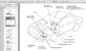
132 Electrical parts 68
1321 Component placement 68
1322 Component list 70
133 Electrical wiring diagram 72
1331 Symbol list 72
1332 Overview 73
1333 Detailed wiring diagram 74
134 Functional description 80
1341 Starting the truck 80
1342 Driving 80
1343 Neutral speed reduction 80
1344 Neutral speed reduction on slopes 80
1345 Braking 80
1346 Lifting the forks 81
1347 Lowering the forks 81
1348 Horn 81
1349 Hour meter 81
13410 Transistor regulator 81
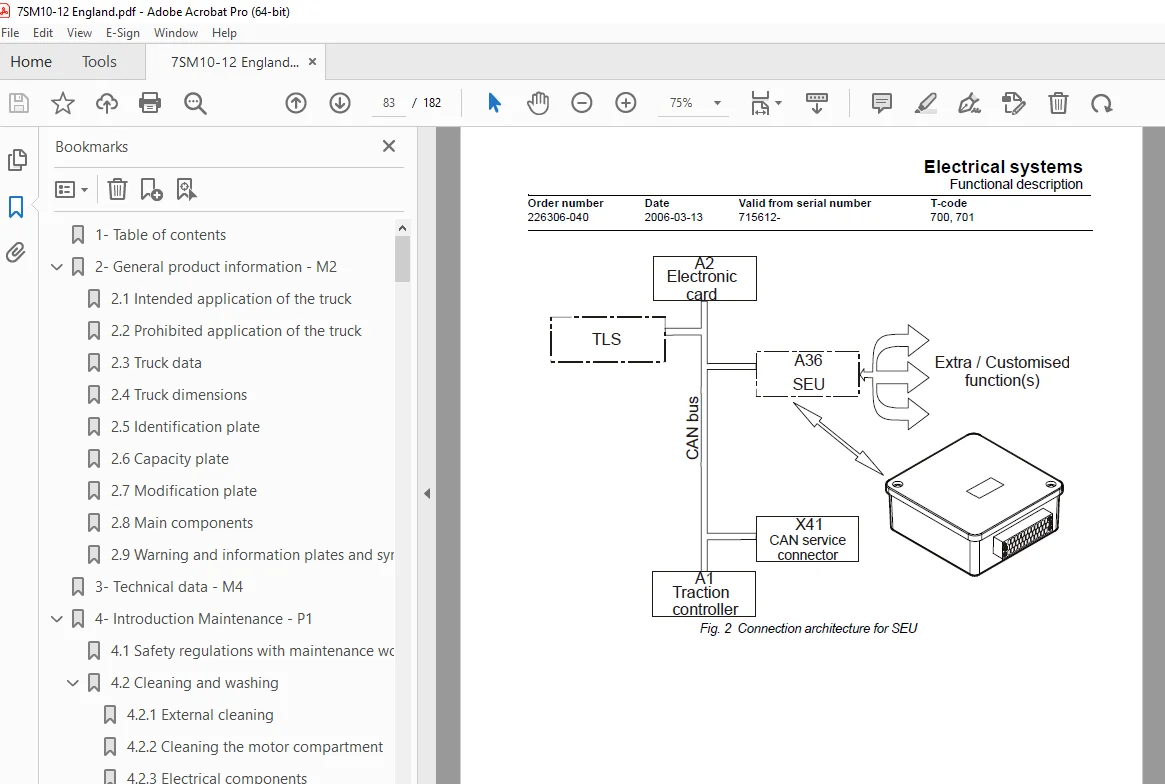
13411 Spider expansion unit (SEU) (option) 82
13412 TLS – Truck log system (optional) 85
General 85
Registration 85
Logging in/out SD16 85
Logging in/out S16 85
Collision sensor 86
Settings 86
13413 ID unit (optional) 87
General 87
Installation 87
Settings 88
135 Parameters 90
1351 General 90
1352 Viewing parameters – without the CAN service key 90
1353 Adjusting operator parameters – without the CAN service key 91
1354 Viewing & changing parameters – CAN service key connected 92
Changing a parameter 93
1355 Operator parameters 94
1356 Parameter description 94
Parameter 1 94
Parameter 2 94
Parameter 3 94
Parameter 4 94
Parameter 5 95
1357 Service parameters 96
1358 Parameter description 97
Parameter 10 97
Parameter 14 97
#15 – Non-configurable options 97
Setting Non-configurable options 97
#16 – Configurable option #1 98
#17 – Configurable option #2 98
#18 – Configurable option #3 98
#19 – Configurable option #4 98
Parameter 20 99
Parameter 21 99
Recommendation on parameter setting for freely ventilated batteries100
Instructions for verifying parameter setting101
Recommendation on parameter setting for valve- controlled batteries (VRLA)102
Instructions for verifying parameter setting103
Parameter 22103
Parameter 25103
Parameter 28103
Parameter 39104
Log-in method & operator parameter access104
Expanded keypad – General104
Expanded keypad – Programming104
1359 Configurable “Option” Parameters107
General107
Summary of base options107
Convention for configurable options108
Detailed option parameter tables110
136 Diagnostic and troubleshooting121
1361 General121
1362 Error code history121
1363 Fault codes122
1364 Transistor regulator errors135
Resetting errors136
Safety136
1365 Built-in Test Function137
Digital inputs/outputs test mode138
Inputs check138
Outputs check139
Option buttons check140
Display test mode140
137 Technical specifications – Curtis 1243141
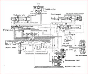
14- Hydraulic system – 6000143
141 General143
142 Hydraulic diagram and components143
1421 Main components143
1422 Description144
Lift144
Lowering144
Operating pressure144
Relief valve144
Pressure switch144
15- Lifting Mast – 7000145
151 Grease the beam flanges and beam ribs145
152 Main lift chain system146
1521 General146
1522 Checking the chain setting146
1523 Chain inspection146
1524 Noise146
1525 Surface rust146
1526 Rusty links146
1527 Stiff links146
1528 Bolt rotation147
1529 Loose bolts147
15210 Outline wear148
15211 Stretching149
15212 Damage149
15213 Damaged discs150
15214 Damaged bolts150
15215 Dirty chain150
153 Cleaning150
154 Lubrication151
16- Battery charger (built-in) – 8340153
161 General153
162 Technical data – charger154
163 Charging154
Machine numbers 723984-936512154
Machine numbers 936513-155
164 Troubleshooting and service155
165 Setting the charger (applies to machine numbers 723984-936512)156
Freely ventilated batteries156
Valve-regulated batteries156
1651 Current levels at different charger settings (applies to machine numbers 936513-)157
Freely ventilated batteries157
Valve-regulated batteries (Evolution type)158
17- Control/computer equipment – 8700159
171 General159
172 Connection159
173 Layout160
1731 Main program screen160
1732 Nodes160
1733 Icons161
1734 Tool buttons and menu bar162
1735 Information window162
1736 Status bar162
174 Connection function163
175 Disconnection function163
176 Downloading program function163
1761 Normal downloading (truck with key)164
1762 Normal downloading (truck with keypad)164
1763 Emergency downloading (truck with keypad)164
1764 Downloading in old versions of logic card165
1765 Emergency downloading (truck with keypad)165
177 Truck report function166
178 Parameters function167
179 Diagnostics function167
1791 Representation of signal colours168
1792 “Tiller arm” tab168
1793 “Drive Controller” tab (transistor regulator – driving)169
1794 “Pump controller” tab (transistor regulator – pump)170
1795 “EPS” steering servo tab171
1710 Other menu functions172
17101 Save to file172
17102 Download from file172
17103 Reset CAN adapter172
17104 Delete error code log172
17105 Reset hour meter172
17106 Read error code log172
17107 Adjust date and time173
17108 Adjusting the hour meter on older cards173
17109 Help173
About the TruckCom application173
171010 Exit173
1711 Specifications173
1712 Installation174
17121 Installation on a PC with Windows® 95/98174
17122 Installation on a PC with Windows XP/ 2000175
Changes in Windows® Control Panel178
17123 Installation on a PC with Windows NT180
17124 In case of communication problems with CAN180
17125 To uninstall180
DESCRIPTION:
Toyota Forklift 7SM10 7SM12 7SM12S Service Manual – PDF DOWNLOAD
Valid from serial number: 715612-
Order number: 226306-040
General product information – M2:
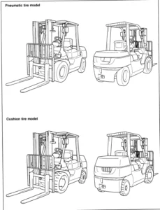
- The truck is a battery-powered support arm truck. In its standard design the truck is equipped with a tiller arm for control while walking.
- The tiller arm is specially designed to provide the best possible operator ergonomy, having all the controls and buttons within easy reach without the operator needing to release the handle. The tiller arm is also equipped with a display showing running time and battery status among other things. The display is also used when the operator wishes to change any of the operator parameters with which the truck can be programmed.
7SM10 has a maximum lifting capacity of 1000 kg.
7SM12 has a maximum lifting capacity of 1200 kg. - The truck has a 24V electrical system and the speed is regulated by means of a transistor controller to provide gentle control of acceleration and speed while driving.
- The forks are raised by means of a powerful hydraulic unit. The lift is electrically controlled using the buttons on the tiller arm. Control of the lowering speed and positioning of the forks when stacking is performed using the truck’s mechanical hydraulic valves.
- The truck can be equipped with different accessories such as ride-on platform, integrated charger, load support and a button for temporary speed reduction. The truck can also be fitted with low temperature oil if it is to be used in cool and humid conditions.
- Note that some of the truck models described in the Operator’s Manual may not be marketed in your country.
S.V 27/02/2025