TOYOTA Forklift 7LOP12, 7LOP12P, 7LOP25, 7LOP25P KSIAZKA SERWISOWA PDF
$28.95
TOYOTA Forklift 7LOP12, 7LOP12P, 7LOP25, 7LOP25P KSIAZKA SERWISOWA – PDF DOWNLOAD
Description
TOYOTA Forklift 7LOP12, 7LOP12P, 7LOP25, 7LOP25P KSIAZKA SERWISOWA – PDF DOWNLOAD
FILE DETAILS:
TOYOTA Forklift 7LOP12, 7LOP12P, 7LOP25, 7LOP25P KSIAZKA SERWISOWA – PDF DOWNLOAD
Language : English
Pages : 238
Downloadable : Yes
File Type : PDF
IMAGES PREVIEW OF THE MANUAL:
TABLE OF CONTENTS:
TOYOTA Forklift 7LOP12, 7LOP12P, 7LOP25, 7LOP25P KSIAZKA SERWISOWA – PDF DOWNLOAD
1- Table of contents 0
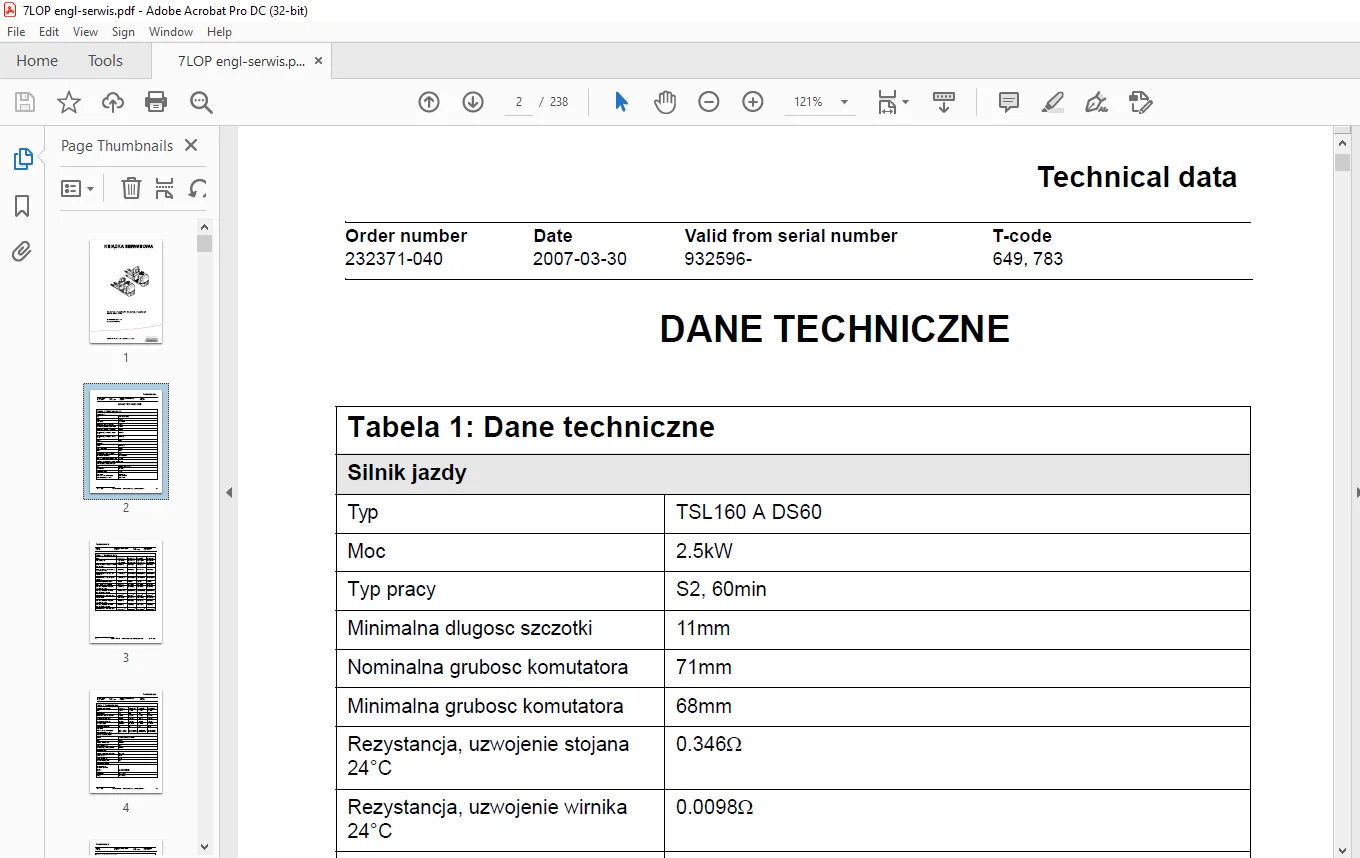
2- Technical data 2
21 Specific tightening torques 6
22 General tightening torques 7
221 Galvanised, non-oiled bolts 7
222 Untreated, oiled bolts 7
3- Maintenance 8
31 Safety rules during maintenance work 8
32 Cleaning and washing 10
321 External cleaning 10
322 Cleaning the motor compartment 10
323 Electric components 10
33 Safe lifting 11
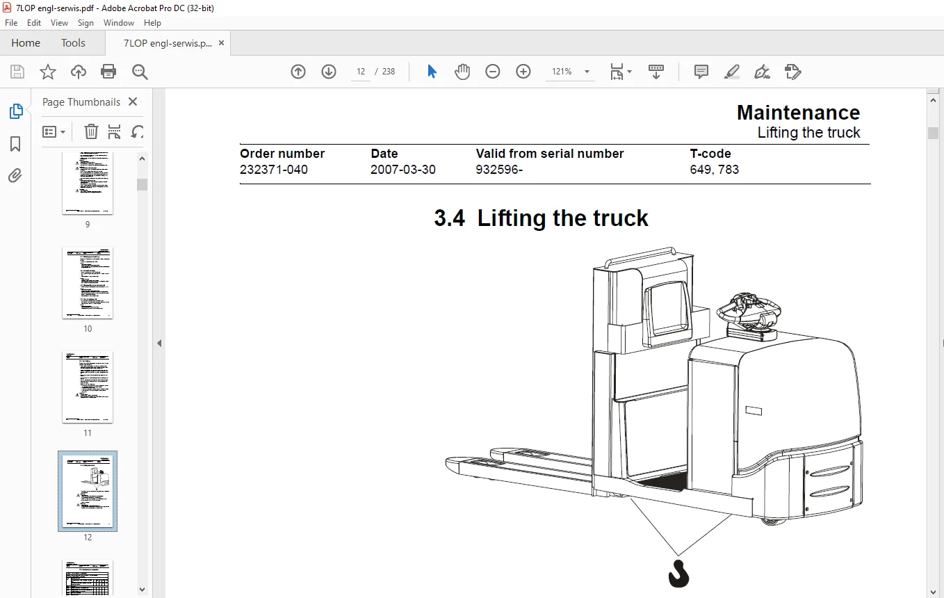
34 Lifting the truck 12
35 Maintenance schedule 13
7LOP12, 7LOP12P 19
7LOP25, 7LOP25P 20
36 Lubrication schedule 21
37 Oil and grease specification 23
4- Tools 24
41 Super Seal connectors 24
42 AMP connectors 25
421 AMP connectors, Multilock series 040 26
43 Molex connectors 26
44 Other tools 27
5- Fork carriage – 0380 30
51 7LOP12, 7LOP12P 30
511 Component overview 30
512 Verifying lateral play 31
513 Disassembly of the fork carriage 32
514 Roller replacement 32
52 7LOP25, 7LOP25P 33
521 Included components 33
522 Disassembly of the fork carriage 35
523 Roller replacement 36
6- Electric drive motor – 1760 38
61 Component parts 38
62 Removing the motor from the truck 40
63 Refitting the motor in the truck 41
64 Service and repairs 41
641 Cleaning 41
7- Drive unit/gear – 2550 42
71 General 42
72 Included components 43
73 Disassembly of the drive unit from the truck 44
74 Assembly of the drive unit in the truck 44
75 Oil inspection or changing oil 45
751 Oil inspection/replenishment 45
752 Changing oil 45
76 Replacing the gasket ring 45
761 Disassembly 45
762 Assembly 46
77 Leakage from top cover 46
78 Pin bolt replacement 47
8- Electromagnetic brake – 3370 48
81 Component overview 48
82 Disassembly 49
821 Inspection 49
83 Assembly 50
84 Manual release of the brake 50
85 Adjustment 50
851 Adjusting the play 50
9- Swivel wheel – 3540 52
91 General 52
92 Component overview 53
93 Maintenance 54
931 Swivel wheel height inspection 54
932 Swivel wheel height adjustment 56
Adjust the swivel wheel 56
Adjustment 56
933 Replacing the swivel wheel 56
Disassembly of the swivel wheel assembly 56
934 Replacing the wheel 57
Disassembly 57
Assembly 57
935 Replacing the wheel bearing 57
10- Electrical steering system – 4300 58
101 General 58
1011 Electrical steering servo 59
102 Component overview 60
103 Adjustment 62
1031 Reference sensor 62
1032 Calibration 62
Parameter 36 62
Parameter 37 62
104 Disassembly/assembly of pushbuttons 63
1041 Replacing the hornbutton/switch 63
1042 Replacing the lifting/lowering pushbutton 64
1043 Replacing the pushbutton 64
105 Replacing the potentiometer 65
106 Inspection and replacement of the lateral movement line (Ergo version) 68
107 Replacing the inductive brake sensor 70
108 Replacing the viscous damper 73
11- Electrical systems – 5000 76
111 General 76
1111 Software/hardware order numbers 76
1112 Nomenclature 77
112 Electrical equipment overview 78
1121 Electric component overview 81
113 Electrical wiring diagram 84
1131 Symbol list 84
1132 Overview 85
1133 Detailed wiring diagram 7LOP12 86
1134 Detailed wiring diagram 7LOP12P 93
1135 Detailed wiring diagram 7LOP25101
1136 Detailed wiring diagram 7LOP25P107
114 Functional description114
1141 Description of the steering servo system126
1142 Spider expansion unit (SEU)126
1143 Speed limitation128
1144 Hour meter and battery condition130
1145 TLS – Truck log system (optional)131
General131
Registration131
Logging in/out SD16131
Logging in/out S16131
Collision sensor132
Settings132
1146 ID unit (optional)132
115 Parameters & adjustments133
1151 General133
1152 Displaying parameters – without the CAN service key133
1153 Adjusting operator parameters – without the CAN service key134
1154 Displaying & changing parameters – CAN service key connected135
Changing a parameter135
1155 List of Operator parameters137
1156 Description of operator parameters138
#1 – Speed, Fork direction138
# 2 – Speed, Drive wheel direction138
# 3 – Acceleration138
# 4 – Neutral braking force138
# 5 – Travel speed, platform > 05 m138
# 6 – Travel speed, walking at side138
# 7 – Neutral braking, walking at side138
1157 List of Service parameters139
1158 Description of Service parameter140
# 10 – PIN code140
To enter a new PIN-code:141
To remove an existing PIN-code:141
# 11 – Reverse braking force142
# 14 – Creep speed142
# 15 – Non-configurable options142
Setting Non-configurable options142
#16 – Configurable option #1143
#17 – Configurable option #2143
#18 – Configurable option #3143
#19 – Configurable option #4143
# 20 – Hour meter selection144
# 21 – Battery size145
# 22 – Machine type146
# 23 – Function selection146
# 24 – N/A146
# 25 – Service interval146
# 28 – Button selection147
# 35 – Automatic log-off147
# 36 – Steer servo calibration147
# 37 – Steering offset148
# 39 – Log-in method & operator parameter access148
Extended keypad – General149
Extended keypad – Programming149
1159 Configurable “Option” Parameters152
General152
Parameter #16 to #19 Configurable options153
Setting Configurable options154
116 Diagnostic and troubleshooting163
1161 General163
1162 Fault code history164
1163 List of error codes165
1164 Transistor regulator troubleshooting and error codes171
General171
Transistor regulator errors172
Resetting errors173
Safety173
1165 Built-in Test Function174
Digital inputs/outputs test mode175
Transistor regulator inputs175
Transistor regulator outputs176
Digital input of logic card [A2]176
Digital input/output to expansion unit [A36]177
Extra functions177
1166 Display test mode178
117 Technical specifications – Curtis 1243179
12- Hydraulic system – 6000180
121 Hydraulic component overview180
122 Hydraulic diagrams181
1221 Component overview183
123 Functional description184
1231 Fork lifting184
1232 Fork lowering184
1233 Platform lifting184
1234 Platform lowering184
1235 Operating pressure184
1236 Relief valve185
1237 Platform cylinder check valve185
1238 Pressure sensor185
124 Adjustments186
1241 Adjusting the pressure limiting valve186
125 Tools187
13- Main lift chain system – 7120188
131 General188
132 Checking the chain setting188
133 Chain inspection188
1331 Noise188
1332 Surface rust188
1333 Rusty links188
1334 Stiff links189
1335 Bolt rotation189
1336 Loose bolts189
1337 Outline wear190
1338 Stretching191
1339 Damage191
13310 Damaged discs192
13311 Damaged bolts192
13312 Dirty chain192
134 Cleaning192
135 Lubrication193
14- Platform – 9130194
141 General194
142 Component overview195
143 Adjustment197
1431 Outer side guide198
15- TruckCom200
151 General200
152 Connection201
153 Layout202
1531 Main program screen202
1532 Nodes202
1533 Icons203
1534 Tool buttons and menu bar203
1535 Information window204
1536 Status bar204
154 Connection function204
155 Disconnection function204
156 Downloading program function205
1561 Normal downloading (truck with key)205
1562 Normal downloading (truck with keypad)205
1563 Emergency downloading (truck with keypad)206
1564 Emergency downloading (truck with keypad)206
1565 Downloading in old versions of logic card206
157 Truck report function207
158 Parameters function208
1581 PIN-code209
1582 Hour meters210
159 Diagnostics function210
1591 Representation of signal colours211
1592 “Tiller arm” tab211
1593 “Drive Controller” tab (transistor regulator driving)212
1594 “Pump controller” tab (transistor regulator pump)213
1595 “EPS” (steering servo tab)214
1596 SEU tab (Extra I/O module)215
1510 Other menu functions215
15101 Save to file215
15102 Download from file216
15103 Reset CAN adapter216
15104 Delete error code log216
15105 Reset hour meter216
15106 Read error code log216
15107 Adjust date and time216
15108 Adjusting the hour meter on older cards216
15109 Help216
About the TruckCom application216
151010 Exit217
1511 Specifications217
1512 Installation217
15121 Installation on a PC with Windows® 95/98217
15122 Installation on a PC with Windows XP/2000219
15123 Installation on a PC with Windows NT219
15124 In case of communication problems with CAN219
1513 Installation of the CPC-USB interface220
1514 To uninstall222
16- Destruction instructions224
161 General224
162 Procedure224
163 Abbreviations224
164 Sorting225
165 Hoods, hatches (0340)226
1651 Disassembly226
1652 Material handling226
166 Battery cover (0340)227
1661 Disassembly227
1662 Material handling227
167 Frame/chassis (0300) and fork frame (0380/7000)228
1671 Disassembly228
1672 Material handling228
168 Seat, cushions (0620)229
1681 Disassembly229
1682 Material handling229
169 Wall/floor covering (0670)230
1691 Disassembly230
1692 Material handling230
1610 Internal fittings (0680)231
16101 Disassembly231
16102 Material handling231
1611 Operator protection (0840)232
16111 Disassembly232
16112 Material handling232
1612 Electric motors (1700)233
16121 Disassembly233
16122 Material handling233
1613 Drive assembly/gear (2550)234
16131 Disassembly234
16132 Material handling234
1614 Wheels (3500)235
16141 Disassembly235
16142 Material handling235
1615 Steering unit (4110)236
16151 Disassembly236
16152 Material handling236
1616 General electronic equipment (5100) 0
16161 Disassembly 0
16162 Material handling 0
1617 Battery cut out connector/ contactor (5190) 0
16171 Disassembly 0
16172 Material handling 0
1618 Extra SEU expansion unit (5730) 0
16181 Disassembly 0
16182 Material handling 0
1619 Hydraulic unit (6100)237
16191 Disassembly237
16192 Material handling237
1620 Hydraulic lines chassis (6230) and main lift cylinders (6610)238
16201 Disassembly238
16202 Material handling238
1621 Charger adaptor (9380) 0
16211 Disassembly 0
16212 Material handling 0
1622 Terminal on board (9410) 0
16221 Disassembly 0
16222 Material handling 0
1623 Other extra equipment, tuck log device (9420) 0
16231 Disassembly 0
16232 Material handling 0
1624 Other extra equipment, load support (9500) 0
16241 Disassembly 0
16242 Material handling 0
1625 Other extra equipment, writing table (9500) 0
16251 Disassembly 0
16252 Material handling 0
1626 Other extra equipment, writing table (9500) 0
16261 Disassembly 0
16262 Material handling 0
1627 Other extra equipment, support (9500) 0
16271 Disassembly 0
16272 Material handling 0
1628 Other extra equipment, collision protection (9500) 0
16281 Disassembly 0
16282 Material handling 0
1629 Other extra equipment, working cage (9130) 0
16291 Disassembly 0
16292 Material handling 0
S.V 26/02/2025