Toyota 6BWC10/15/20 6BWS11/15/20 6BWR15 Electric Walkie Lift Truck Service Manual PDF
$29.95
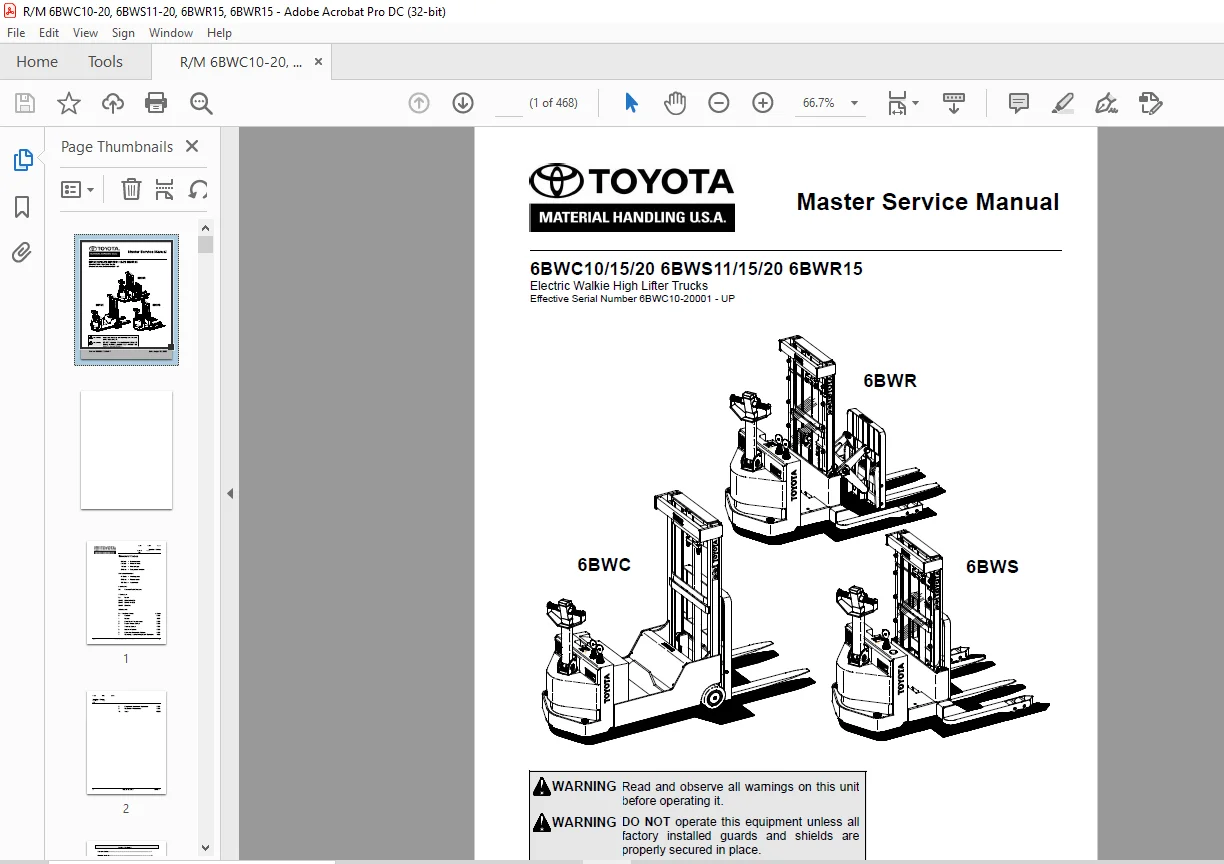
Toyota 6BWC10/15/20 6BWS11/15/20 6BWR15 Electric Walkie Lift Truck Service Manual – PDF DOWNLOAD
Effective Serial Number 6BWC10-20001 – UP
Part no: 00700-CL3WS-RP
Description
Toyota 6BWC10/15/20 6BWS11/15/20 6BWR15 Electric Walkie Lift Truck Service Manual – PDF DOWNLOAD
FILE DETAILS:
Toyota 6BWC10/15/20 6BWS11/15/20 6BWR15 Electric Walkie Lift Truck Service Manual – PDF DOWNLOAD
Language : English
Pages : 468
Downloadable : Yes
File Type : PDF
IMAGES PREVIEW OF THE MANUAL:
TABLE OF CONTENTS:
Toyota 6BWC10/15/20 6BWS11/15/20 6BWR15 Electric Walkie Lift Truck Service Manual – PDF DOWNLOAD
Effective Serial Number 6BWC10-20001 – UP
Part no: 00700-CL3WS-RP
R/M 6BWC10/15/20, 6BWS11/15/20 AND 6BWR15 SERIAL NUMBER: 6BWC10-20001 & UP 1
Standard Codes 3
Table of Contents 5
Warning Symbols 15
Warning Levels 15
Prohibitory Symbols 16
Ordinance Symbols 16
Safety 17
General Safety 17
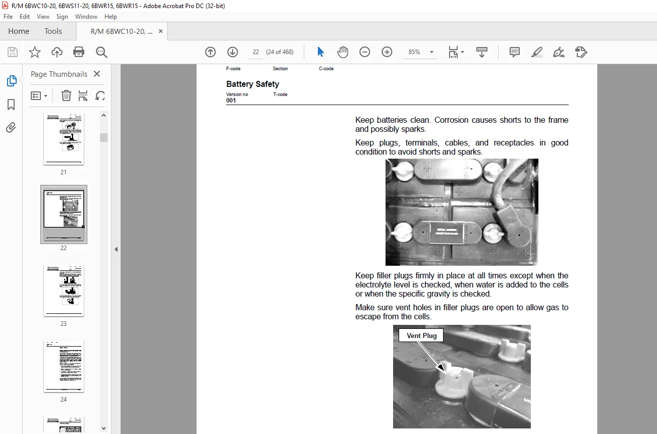
Battery Safety 21
Static Safety 26
Welding Safety 27
Introduction, Service Manual 29
Contents, Section M 31
Machine Information 31
General Product Information 33
Presentation of Walkie Trucks 33
Truck Side Views 34
Intended Truck Application 34
Prohibited Truck Application 34
Truck Data 35
6BWC10 Dimensions 36
6BWC15 Dimensions 37
6BWC20 Dimensions 38
6BWS11 Dimensions 39
6BWS15 Dimensions 40
6BWS20 Dimensions 41
6BWR15 Dimensions 42
Data Plate 43
Main Components 44
Inch (SAE) and Metric Fasteners 47
Introduction 47
Nomenclature, Threads 48
Strength Identification 49
Conversion of Metric and English Units 56
Technical Service Data 59
Ordering Spare Parts 63
Contents, Section P 65
Planned Maintenance 65
Introduction, Maintenance 67
Jacking Truck Off The Floor 68
Elevate Rear of Truck 68
Elevate Either Side of Truck 68
Lubricants 69
Standard 69
Corrosion 69
Cold Storage 70
Service Schedule 73
Planned Maintenance Schedule 73
Planned Maintenance Procedures 78
Services Performed Daily or Every 8 Operating Hours 78
Services Performed Monthly or Every 120 Operating Hours 79
Services Performed Every 480 or 960 Operating Hours 82
Services Performed Annually or Every 1400 Operating Hours 83
Lubrication Chart 85
Oil and Grease Specifications 86
Approved Oils and Grease 86
6BWC Grease & Mast Adjustment Points Location 87
6BWS Grease & Mast Adjustment Points Location 88
6BWR Grease & Mast Adjustment Points Location 89
Contents, Section S 91
Service Instructions 91
Frame/Chassis 93
General 95
Main Components 95
Inspection Covers 97
Battery Roller (Optional)105
Battery Cover, Optional (6BWS11 “EE” Trucks Only)107
Inspection107
Removal107
Installation108
Battery Rollers108
Inspection108
Replacement108
Driver Controls, One Spool109
Removal111
Installation112
Driver Controls, Two Spool113
Removal116
Installation117
Decals119
Decal with Protective Sheet119
Decal without Protective Sheet119
Motor Maintenance Schedule/Troubleshooting121
General Information121
Operating Conditions121
Troubleshooting122
Motor Repair129
Pump Motor129
Pump Motor Removal130
Pump Motor Installation130
Drive Motor131
Brush Replacement135
Drive Motor Removal135
Drive Motor Installation136
Component Repair138
Disassembly138
Inspection140
Drive End Head140
Commutator End Head140
Bearings140
Brush and Commutator141
Armature143
Frame and Field Assembly144
Assembly/Testing145
Transmission147
System Description147
Troubleshooting147
Kick Panel148
Transmission Repair149
Removal150
Installation151
Transmission Assembly153
Disassembly154
Assembly154
Axle Seal156
Removal156
Installation156
Parking Brake System159
Brake Theory of Operation161
Brake Adjustment162
Brake Shoe Removal / Installation163
Drive Wheel165
Removal165
Installation166
Tire Pressing Procedure167
Support/Swivel Wheel169
Maintenance and Adjustments172
Caster Adjustment173
Troubleshooting174
Stabilizing Caster174
Load Wheels175
Removal and Installation178
Caster Assembly179
Disassembly180
Inspection181
Assembly182
Installation183
Steering Arm/Wheel, Tiller Arm185
Removal186
Inspection187
Installation188
Steering Arm/Wheel, Head189
Control Handle Head190
Removal190
Installation190
Direction Control Switches191
Raise, Lower, and Horn Switches193
Potentiometer196
Removal196
Installation197
Reverser Assembly Replacement201
Electrical Functions203
General203
Adjustable Settings203
References203
Key Switch S17 in ON Position204
Operating Arm in Drive Position, S10, Brake Switch Closed204
Travel Request, Forks First204
Travel Request, Forks Trailing204
Reversing/Motor Brake Forks First to Forks Trailing Direction205
Reversing/Motor Brake Forks Trailing to Forks First Direction205
Reverser Switch205
Lifting Forks205
Lowering Forks206
Horn206
Options206
Lifting Forks (Manual Valve)206
Tilting Forks206
Side Shifting Forks206
Extend/Retract Forks207
Electrical Symbols209
Electrical Schematics215
Battery221
Removal221
Installation222
Battery Maintenance223
Battery Inspection and Care223
Battery Exterior Cleaning224
Charging224
Storage225
Battery History Record225
Battery Connector227
Location227
Inspection228
Installation228
200 Amp System Line Contactor231
Replacement231
Removal231
Installation231
300 Amp System Line Contactor (6BWC15/20 only)233
Maintenance233
Removal/Replacement of Contact Tips234
200/300 Amp System “EE” Line Contactor235
Maintenance235
Removal/Replacement of Contact Tips236
Battery Controller/Hourmeter/Lift Interrupt239
General Information239
Electrical240
Voltage240
Battery Controller (BC)241
General Information241
Reset243
Key Switch243
Hourmeter244
Troubleshooting244
Battery Discharge Indicator (BDI)244
Hourmeter247
Start/Stop Switches249
General249
Test/Inspection249
Master Control On/Off Switch (S21)251
Inspection251
Removal251
Installation251
Light Assemblies253
Warning Lights (Option)253
Removal255
Installation255
Travel/Back-up Alarm (Option)256
Removal256
Installation256
Transistor Controller257
Basics Of Circuit Operation257
Control Features259
Maintenance260
Safety260
Cleaning260
Motor Circuit261
Control Circuit262
Troubleshooting Guidelines263
General265
Shorts to Frame Test266
Definitions270
Diagnostics and Troubleshooting271
Handset Diagnostics271
Troubleshooting271
Troubleshooting Chart273
Technical Specification278
Troubleshooting Chart Using Handset279
Transistor Controller Troubleshooting281
Troubleshooting Chart Index281
Troubleshooting Charts282
Hydraulic System301
General301
Description of Function301
Main Components302
Lift (Solenoid Valve)302
Lift (Mechanical Valve)302
Lower (Solenoid Valve)302
Lower (Mechanical Valve)302
Relief Pressure302
Compensating Cylinder303
Reach (Solenoid Valve)303
Tilt (Solenoid Valve)303
Sideshift (Solenoid valve)303
Maintenance304
Adjustments305
Troubleshooting306
Primary Malfunctions307
Definitions308
Removal309
Installation311
Hydraulic Schematics313
Hydraulic Fluid317
Hydraulic Fluid Selection317
Changing Hydraulic System Fluid317
System Draining318
Refilling System319
Bleeding Hydraulic System320
Hydraulic Tank321
Removal322
Installation322
Hydraulic Pump Assembly323
Disassembly325
Inspection326
Assembly327
One Spool Control Valve329
Operators Controls Removal330
Control Valve Disassembly and Inspection330
Operators Controls Installation331
Two Spool Control Valve332
Operators Controls Removal333
Control Valve Disassembly and Inspection333
Operators Controls Installation334
Lift Cylinder, Two Stage Mast339
Removal339
Disassembly340
Assembly340
Installation340
Two Stage Full Freelift Mast Cylinder Repair341
Removal341
Disassembly342
Assembly342
Installation342
Two Stage Full Freelift Mast Staging Cylinder Repair343
Removal343
Disassembly344
Assembly344
Installation344
Lift Cylinder, Three Stage Mast345
Repair348
Removal348
Disassembly349
Assembly349
Installation349
Reach Cylinder, 6BWR15351
Removal353
Disassembly354
Inspection355
Assembly356
Installation357
Tilt Cylinder359
Removal361
Disassembly362
Inspection363
Assembly364
Installation365
Removal367
Disassembly368
Inspection369
Assembly370
Installation371
Shimming Carriage with Mast on Truck401
Repair403
Removal403
Disassembly404
Assembly405
Installation407
Lift Chain408
Lift Chain Adjustment386
Lift Chain Maintenance386
Lift Chain Inspection386
Lift Chain Replacement393
Mast, Three Stage395
Shimming Carriage with Mast on Truck401
Repair403
Removal403
Disassembly404
Assembly405
Installation407
Lift Chain408
Sideshifter409
Mounting Instructions411
Installation411
Operation412
Maintenance412
Carriage Removal413
Upper Pad Replacement413
Lower Pad Replacement414
Cylinder415
Troubleshooting416
No Sideshifting416
Very Slow Sideshifting416
Irregular Sideshifting417
Single Reach, 6BWR419
Maintenance421
Inspection421
Adjustment422
Repair426
Disassembly426
Assembly428
Carriage Bumpers430
Reach Adjustment430
Fork Carriage Pivot Pins432
Carriage Roller Bearings432
Removal432
Installation432
Removal434
Inspection434
Installation435
Load Backrest437
Removal438
Installation438
Handset Operation439
Operating Modes442
Revert to Previous Settings445
Handset Self Test445
Electrical Controllers (Handset)447
Display Screen448
Menu Navigation Key448
Data Inc/Dec Key448
Bookmark Keys448
Operation449
Menu Structure449
Main Menu450
Interface Protocols and Backward Compatibility451
Parameter Changing452
Real-Time Monitoring452
Reading Faults and Diagnostic History File453
Cloning and Restoring the Previous Programming453
Information Displays454
Programmer SetUp454
Index455
Circuit Diagrams459
List of Symbols464
S.V 25/02/2025
![1993 Toyota Celica 1.6L 4-CYL - VIN [A] & 1.8L 4-CYL - VIN [A] Service Manual - PDF DOWNLOAD](https://heydownloads.com/wp-content/uploads/2022/11/1993-Toyota-Celica-1.6L-4-CYL-VIN-A-1.8L-4-CYL-VIN-A-Service-Manual-2-300x215.webp)