

TCM E820-3 Wheel Loader Troubleshooting Technical Manual M-025-MAE – PDF DOWNLOAD
FILE DETAILS:
TCM E820-3 Wheel Loader Troubleshooting Technical Manual M-025-MAE – PDF DOWNLOAD
Language : English
Pages : 251
Downloadable : Yes
File Type : PDF
Size: 4.52 MB
IMAGES PREVIEW OF THE MANUAL:
DESCRIPTION:
TCM E820-3 Wheel Loader Troubleshooting Technical Manual M-025-MAE – PDF DOWNLOAD
INTRODUCTION
TO THE READER
• This manual is written for an experienced technician to provide technical information needed to maintain
and repair this machine.
• Be sure to thoroughly read this manual for correct product information and service procedures.
ADDITIONAL REFERENCES
• Please refer to the other materials (operator’s manual, parts catalog, engine technical material and Hitachi training material etc.) in addition to this manual.
MANUAL COMPOSITION
• This manual consists the Technical Manual and the Workshop Manual.
• Information included in the Technical Manual: technical information needed for redelivery and delivery, operation and activation of all devices and systems, operational performance tests, and troubleshooting procedures.
• Information included in the Workshop Manual: technical information needed for maintenance and repair of the machine, tools and devices needed for maintenance and repair, maintenance standards, and removal/installation and assemble/
disassemble procedures.
FOLLOW SAFETY INSTRUCTIONS:
TABLE OF CONTENTS:
TCM E820-3 Wheel Loader Troubleshooting Technical Manual M-025-MAE – PDF DOWNLOAD
INTRODUCTION 2
SAFETY 4
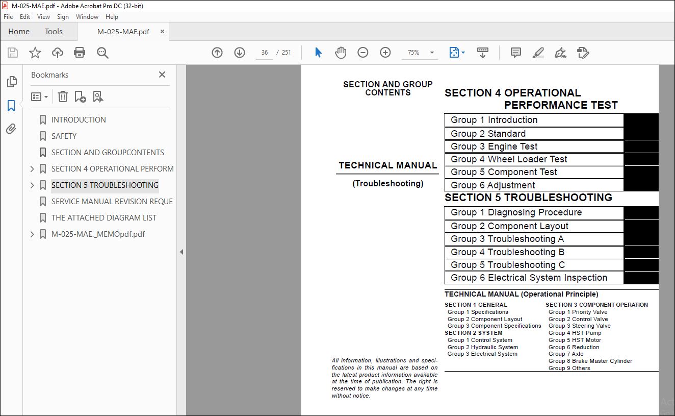
SECTION AND GROUPCONTENTS 36
SECTION 4 OPERATIONAL PERFORMANCE TEST 38
Group 1 Introduction 40
Operational Performance Tests 40
Preparation for Performance Tests 41
Group 2 Standard 42
Operational Performance Standard Table 42
Group 3 Engine Test 48
Engine Speed 48
Group 4 Wheel Loader Test 50
Travel Speed 50
Service Brake Capacity 51
Service Brake / Parking Brake Wear 53
Parking Brake Capacity 55
Bucket Stopper and Bell Crank Stopper Clearance 57
Hydraulic Cylinder Cycle Time 59
Dig Function Drift Check 61
Control Lever Operating Force 62
Control Lever Stroke 63
Group 5 Component Test 64
Main Pump Delivery Pressure 64
HST Pump Delivery Pressure 65
HST Charging Pump Delivery Pressure 66
Main Relief Pressure 67
HST Pump Relief Pressure 69
Steering Relief Pressure 70
Overload Relief Pressure 71
Group 6 Adjustment 74
Fan Belt Tension Adjustment 74
SECTION 5 TROUBLESHOOTING 78
Group 1 Diagnosing Procedure 80
Introduction 80
Diagnosing Procedure 81
How to Operate Service Mode of Monitor 84
How to Use Error Code Readout Switch 85
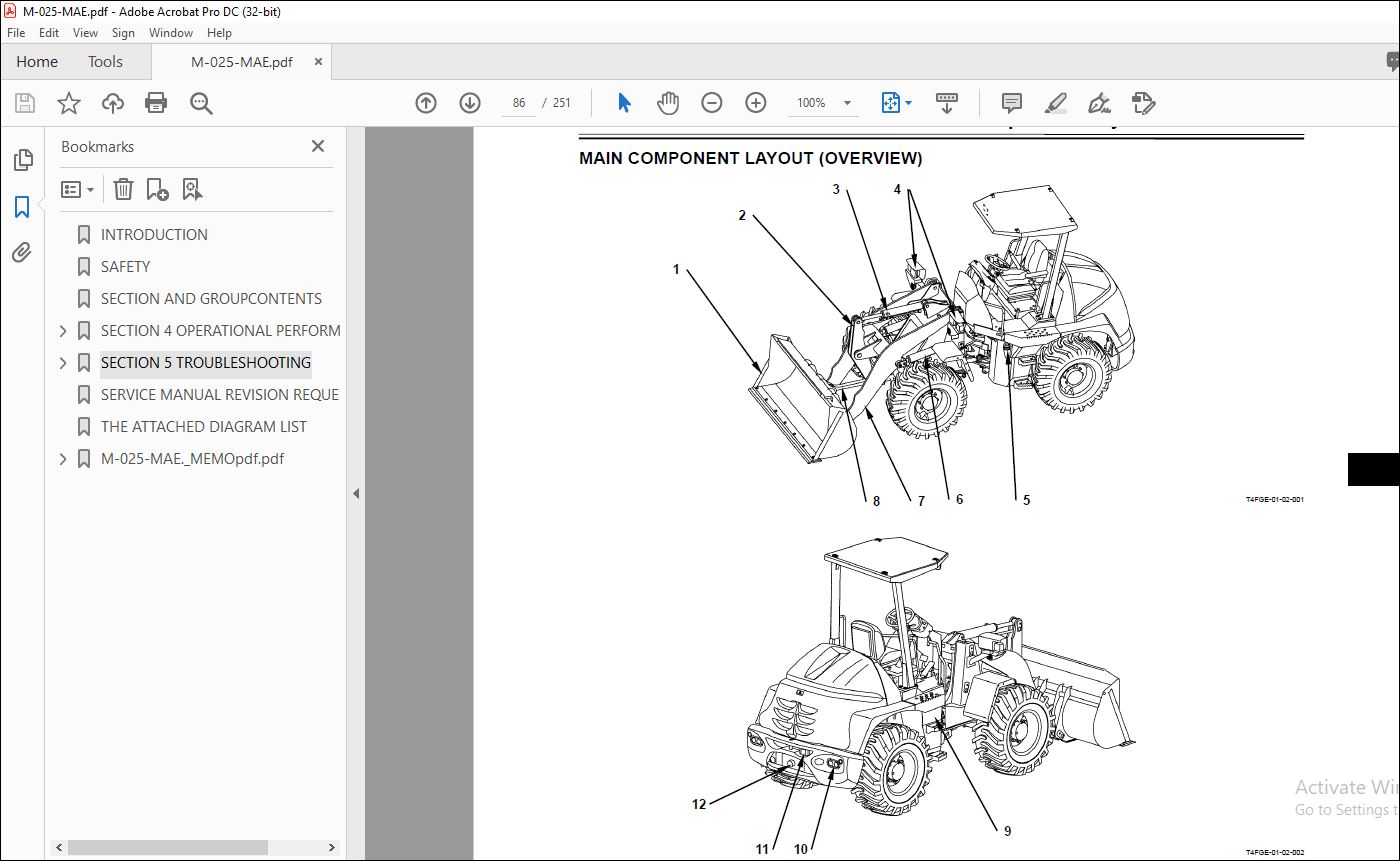
Group 2 Component Layout 86
Main Component Layout (Overview) 86
Main Component Layout (Body) 87
Main Component Layout (Travel System) 88
Electrical System (Overview) 89
Electrical System (Inside of Cab) 90
Engine 95
HST Pump / Main Pump 95
Reduction Gear / HST Motor 96
Control Valve 96
Group 3 Troubleshooting A 100
Troubleshooting A Procedure 100
HST Control Unit Error Code List 101
HST Control Unit Error Code 1-1 102
HST Control Unit Error Codes 2-1, 2-2 103
HST Control Unit Error Code 2-3 105
HST Control Unit Error Code 2-4 107
HST Control Unit Error Code 3-1 109
HST Control Unit Error Code 3-2 111
HST Control Unit Error Codes 3-3, 3-4 113
HST Control Unit Error Code 3-5 115
HST Control Unit Error Codes 4-1, 4-2 116
Group 4 Troubleshooting B 118
Troubleshooting B Procedure (Machine Diagnosis by Using Trouble Symptom) 118
Engine System Failure List 119
Engine System Troubleshooting 120
Vehicle System Failure List 129
Travel System Troubleshooting 131
Brake System Troubleshooting 151
Steering System Troubleshooting 159
Front Attachment System Troubleshooting 164
Group 5 Troubleshooting C 190
Troubleshooting C Procedure (Trouble Shooting for Monitor) 190
Malfunction of Indicator Light Check System 191
Malfunction of Coolant Temperature Gauge 193
Malfunction of Fuel Gauge 195
Malfunction of Turn Signal Indicators (Left and Right) 197
Malfunction of Hazard Light Indicator 198
Malfunction of High Beam Indicator 199
Malfunction of Working Light Indicator 201
Malfunction of Preheat Indicator 203
Malfunction of HST Warning Indicator 204
Malfunction of Air Filter Restriction Indicator 205
Malfunction of Engine Oil Low Pressure Indicator 208
Malfunction of Overheat Indicator 209
Malfunction of Stop Indicator 210
Malfunction of Service Indicator 211
Malfunction of Parking Brake Indicator 213
Malfunction of Clearance Light Indicator 215
Malfunction of Brake Oil Low Level Indicator 217
Malfunction of Discharge Warning Indicator 219
Malfunction of Monitor Display 221
Malfunction of Ride Control Indicator 222
Group 6 Electrical System Inspection 224
Precautions for Inspection and Maintenance 224
Instructions for Disconnecting Connectors 226
Fuse Inspection 229
Fusible Link Inspection 231
Battery Voltage Check 232
Alternator Check 233
Continuity Check 234
Voltage and Current Measurement 235
SERVICE MANUAL REVISION REQUEST FORM 0
THE ATTACHED DIAGRAM LIST 241
M-025-MAE _MEMOpdf pdf 0
INTRODUCTION 0
SAFETY 0
SECTION AND GROUPCONTENTS 0
SECTION 4 OPERATIONAL PERFORMANCE TEST 0
Group 1 Introduction 0
Operational Performance Tests 0
Preparation for Performance Tests 0
Group 2 Standard 0
Operational Performance Standard Table 0
Group 3 Engine Test 0
Engine Speed 0
Group 4 Wheel Loader Test 0
Travel Speed 0
Service Brake Capacity 0
Service Brake / Parking Brake Wear 0
Parking Brake Capacity 0
Bucket Stopper and Bell Crank Stopper Clearance 0
Hydraulic Cylinder Cycle Time 0
Dig Function Drift Check 0
Control Lever Operating Force 0
Control Lever Stroke 0
Group 5 Component Test 0
Main Pump Delivery Pressure 0
HST Pump Delivery Pressure 0
HST Charging Pump Delivery Pressure 0
Main Relief Pressure 0
HST Pump Relief Pressure 0
Steering Relief Pressure 0
Overload Relief Pressure 0
Group 6 Adjustment 0
Fan Belt Tension Adjustment 0
SECTION 5 TROUBLESHOOTING 0
Group 1 Diagnosing Procedure 0
Introduction 0
Diagnosing Procedure 0
How to Operate Service Mode of Monitor 0
How to Use Error Code Readout Switch 0
Group 2 Component Layout 0
Main Component Layout (Overview) 0
Main Component Layout (Body) 0
Main Component Layout (Travel System) 0
Electrical System (Overview) 0
Electrical System (Inside of Cab) 0
Engine 0
HST Pump / Main Pump 0
Reduction Gear / HST Motor 0
Control Valve 0
Group 3 Troubleshooting A 0
Troubleshooting A Procedure 0
HST Control Unit Error Code List 0
HST Control Unit Error Code 1-1 0
HST Control Unit Error Codes 2-1, 2-2 0
HST Control Unit Error Code 2-3 0
HST Control Unit Error Code 2-4 0
HST Control Unit Error Code 3-1 0
HST Control Unit Error Code 3-2 0
HST Control Unit Error Codes 3-3, 3-4 0
HST Control Unit Error Code 3-5 0
HST Control Unit Error Codes 4-1, 4-2 0
Group 4 Troubleshooting B 0
Troubleshooting B Procedure (Machine Diagnosis by Using Trouble Symptom) 0
Engine System Failure List 0
Engine System Troubleshooting 0
Vehicle System Failure List 0
Travel System Troubleshooting 0
Brake System Troubleshooting 0
Steering System Troubleshooting 0
Front Attachment System Troubleshooting 0
Group 5 Troubleshooting C 0
Troubleshooting C Procedure (Trouble Shooting for Monitor) 0
Malfunction of Indicator Light Check System 0
Malfunction of Coolant Temperature Gauge 0
Malfunction of Fuel Gauge 0
Malfunction of Turn Signal Indicators (Left and Right) 0
Malfunction of Hazard Light Indicator 0
Malfunction of High Beam Indicator 0
Malfunction of Working Light Indicator 0
Malfunction of Preheat Indicator 0
Malfunction of HST Warning Indicator 0
Malfunction of Air Filter Restriction Indicator 0
Malfunction of Engine Oil Low Pressure Indicator 0
Malfunction of Overheat Indicator 0
Malfunction of Stop Indicator 0
Malfunction of Service Indicator 0
Malfunction of Parking Brake Indicator 0
Malfunction of Clearance Light Indicator 0
Malfunction of Brake Oil Low Level Indicator 0
Malfunction of Discharge Warning Indicator 0
Malfunction of Monitor Display 0
Malfunction of Ride Control Indicator 0
Group 6 Electrical System Inspection 0
Precautions for Inspection and Maintenance 0
Instructions for Disconnecting Connectors 0
Fuse Inspection 0
Fusible Link Inspection 0
Battery Voltage Check 0
Alternator Check 0
Continuity Check 0
Voltage and Current Measurement 0
SERVICE MANUAL REVISION REQUEST FORM 0
THE ATTACHED DIAGRAM LIST 0
VIDEO PREVIEW OF THE MANUAL:
PLEASE NOTE:
- This is not a physical manual but a digital manual – meaning no physical copy will be couriered to you. The manual can be yours in the next 2 mins as once you make the payment, you will be directed to the download page IMMEDIATELY.
- This is the same manual used by the dealers inorder to diagnose your vehicle of its faults.
- Require some other service manual or have any queries: please WRITE to us at [email protected]
S.V


