Taylor-Dunn P With Contactor Control Maintenance Instructions Parts Manual PDF
$18.95
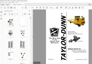
Taylor-Dunn P With Contactor Control Maintenance Instructions Parts Manual S.NO. 25822-53150 – PDF DOWNLOAD
Description
Taylor-Dunn P With Contactor Control Maintenance Instructions Parts Manual S.NO. 25822-53150 – PDF DOWNLOAD
FILE DETAILS:
Taylor-Dunn P With Contactor Control Maintenance Instructions Parts Manual S.NO. 25822-53150 – PDF DOWNLOAD
Language : English
Pages : 80
Downloadable : Yes
File Type : PDF
IMAGES PREVIEW OF THE MANUAL:
TABLE OF CONTENTS:
Taylor-Dunn P With Contactor Control Maintenance Instructions Parts Manual S.NO. 25822-53150 – PDF DOWNLOAD
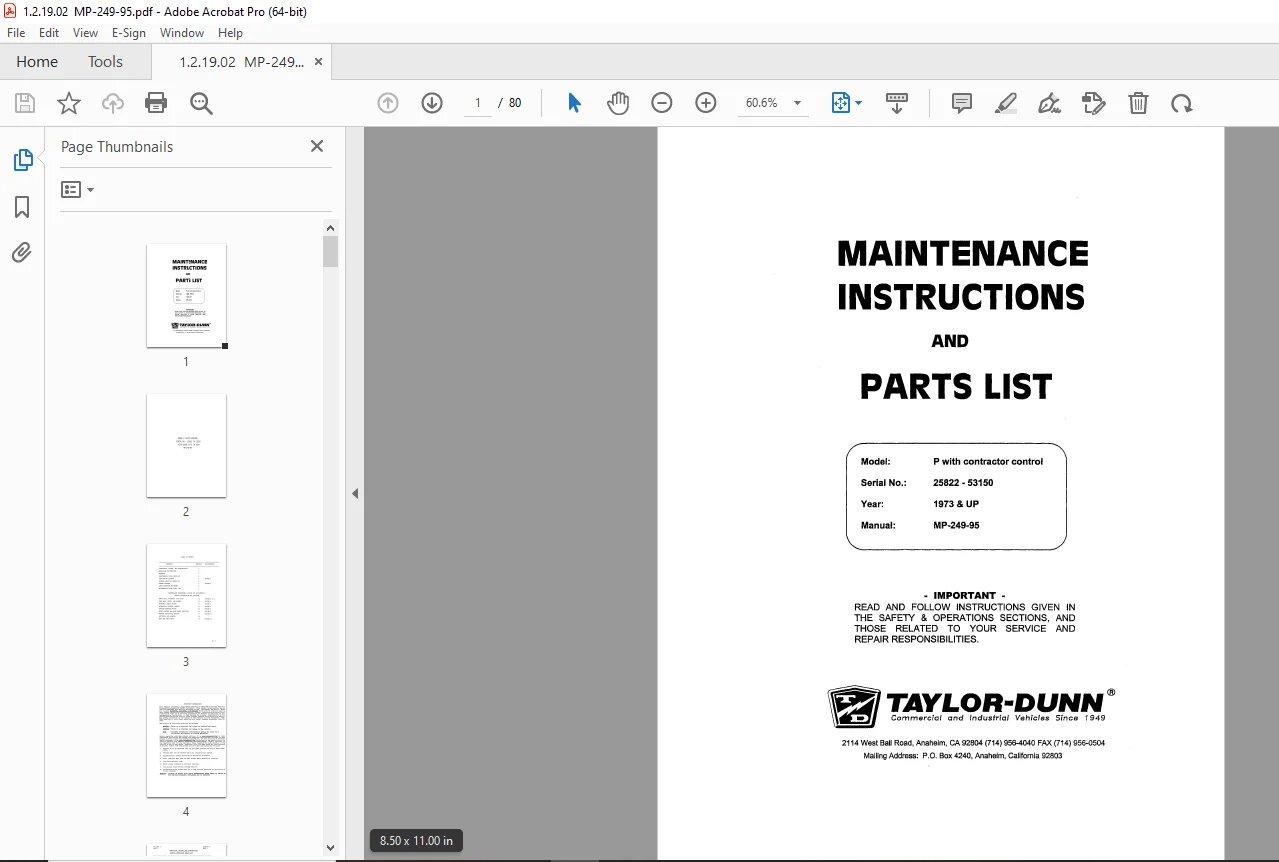
MP-249-95 Maintenance Instructions and Parts List 1
Table of Contents 3
Important Information 4
Section A: Inspection, Safety, and Introduction 5
Section B: Operating Instructions 7
Section C: 90 Day Warranty10
Section D: Maintenance Guide Checklist11
Section E: Lubrication Diagram12
Section F: Trouble Shooting Procedures13
Section G: Wiring Diagram15
Section H: Parts Ordering Procedure16
Section I: Suggested Spare Parts List17
Section J1: Front Axle, Steering and Tires – Maintenance Procedures20
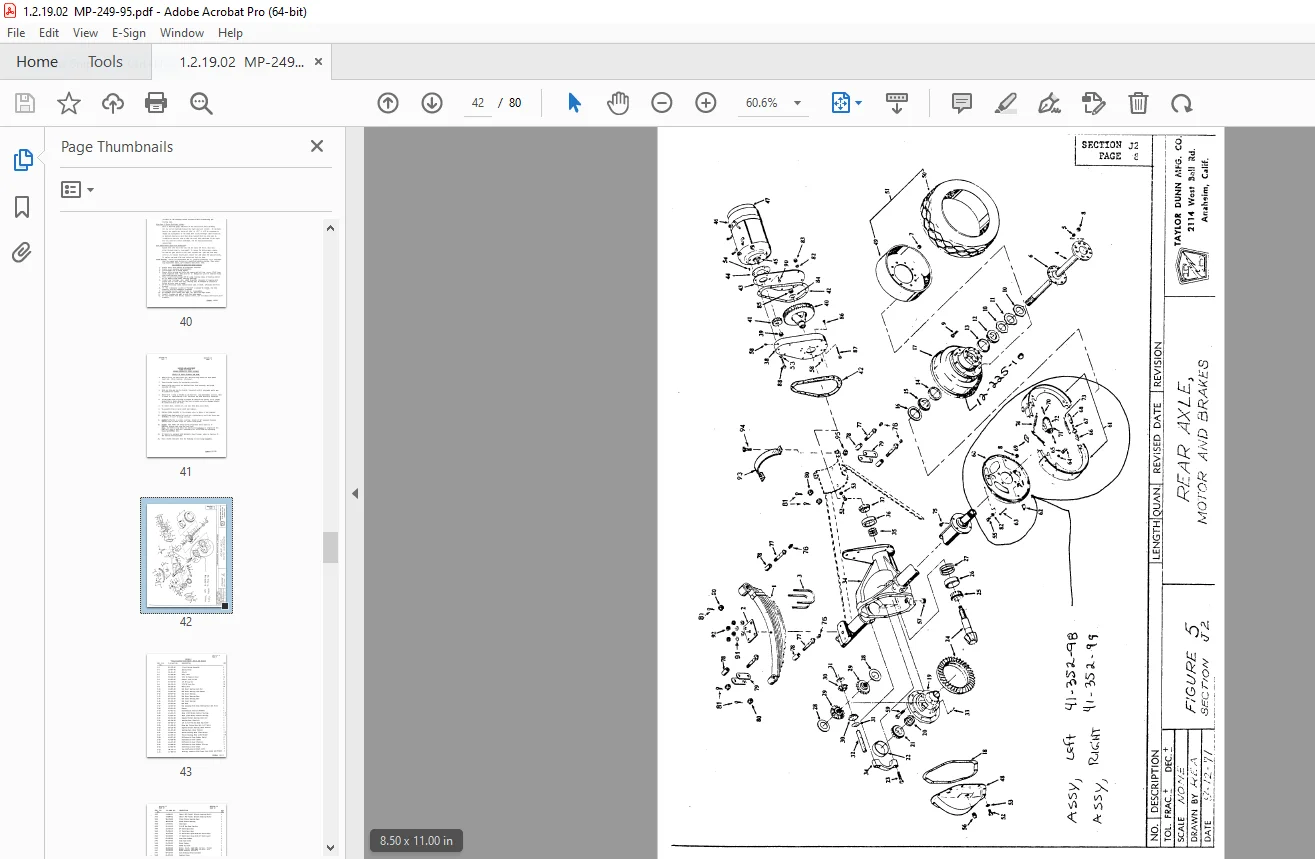
Section J2: “Full Floating” Rear Axle, Motor and Brakes – Maintenance Procedures35
Section J3: Hydraulic Brake System – Maintenance Procedures47
Section J4: Mechanical Control Linkage – Maintenance Procedures53
Section J5: Forward/Reverse Control Switch – Maintenance Procedures57
Section J6: C-290 SCR – Speed Control & Main Power Switching61
Section J7: General Electrical System – Maintenance Procedures72
Section J8: Batteries – Maintenance Procedures73
Series “SA” Battery Chargers – Operating & Servicing Handbook76
Notice of Change80
DESCRIPTION:
Taylor-Dunn P With Contactor Control Maintenance Instructions Parts Manual S.NO. 25822-53150 – PDF DOWNLOAD
OPERATING INSTRUCTIONS :
The controls on your Taylor-Dunn vehicle have been designed and located for convenience of operation and efficient performance. Before driving your vehicle for the first time, familiarize yourself with each of the controls. Read the following instruetions and with power “OFF”, operate each control 1. By following this suggestion you will attain a “feel” for their operation prior to traveling under power for the first time.
- STEERING The steering wheel and steering system is similar to automotive types. Turn the steering wheel to the right (or clockwise) for a right turn and left (or counterclockwise) for a left turn.
- KEY LOCK Your vehicle is equipped with a keyed lock located in the dash panel. It is designed to lock the switch in the neutral position only. The key will remove from the lock in the locked position (neutral) only. ‘
- BRAKE – AUTOMATIC (DEADMAN) The drivers seat operates the automatic “Deadman” brake. The weight of the person moves the seat down and operates the brake release linkage. The brake is automatically applied when the seat is vacated. In conjunction the power to the drive motor is disconnected as the brake is applied.
- BRAKE (FOOT) The brake pedal is designed and located for right foot operation. It is the pedal located to the left of accelerator pedal. It functions the same as the brake pedal in your automobile. Depressing the pedal applies the braking action. The greater the effort applied to the pedal with your foot, the greater the braking action to your vehicle. Removing your foot from the pedal allows immediate release of the braking action to your vehicle.
- FORWARD-REVERSE SWITCH The forward-reverse switch is located on the steering column. It is operated by the handle. To place in forward position push the handle forward. To place in reverse position pull the handle backward towards rear
G.B 25/01/25