Taylor-Dunn P 2-49 Operation & Maintenance Parts Manual S.NO.53151-814945 PDF
$28.95
Taylor-Dunn P 2-49 Operation & Maintenance Parts Manual S.NO.53151-814945 – PDF DOWNLOAD
Description
Taylor-Dunn P 2-49 Operation & Maintenance Parts Manual S.NO.53151-814945 – PDF DOWNLOAD
FILE DETAILS:
Taylor-Dunn P 2-49 Operation & Maintenance Parts Manual S.NO.53151-814945 – PDF DOWNLOAD
Language : English
Pages : 359
Downloadable : Yes
File Type : PDF
IMAGES PREVIEW OF THE MANUAL:
TABLE OF CONTENTS:
Taylor-Dunn P 2-49 Operation & Maintenance Parts Manual S.NO.53151-814945 – PDF DOWNLOAD
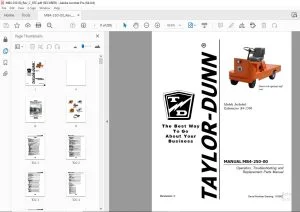
MP-249-00 Operation and Maintenance Manual with Parts List 1
Table of Contents 2
Section C: 90 Day Warranty 3
MP-249-00 Operation and Maintenance Manual with Parts List 4
Important Information 5
Table of Contents 6
Section A: Inspection, Safety, and Introduction 7
Section B: Operating Instructions 9
Section D: Maintenance Guide Checklist 15
Section E: Lubrication Diagram 16
Section F: Trouble Shooting Procedures 17
Section G: Wiring Diagram 19
Section H: Parts Ordering Procedure 22
Section I: Suggested Spare Parts List 23
Section J1: Front Axle, Steering and Tires – Maintenance Procedures 26
Section J2: “Full Floating” Rear Axle, Motor and Brakes – Maintenance Procedures 32
Section J2M: Electric Motors – Maintenance, Service and Adjustment 44
Section J3: Hydraulic Brake System – Maintenance Procedures 47
Section J4: Mechanical Control Linkage – Maintenance Procedures 53
EV-1 SCR Control for Electric Vehicles 57
Section M: EV-1 SCR-1 System 88
Section M1: EV-1 Forward/Reverse Switch – Service and Adjustment 92
Section M2: EV-1 SCR Control Accelerator Switch 94
Section M3B: EV-1 SCR 150 AMP Contactor Panel 95
Section M4: EV-1 SCR Control Module 98
EV-1 SCR Control Accelerator Switch100
Section J6: Speed Control Program Switch – Maintenance Procedures103
Section J7: General Electrical System – Maintenance Procedures114
Section J8: Batteries – Maintenance Procedures115
Series “SA” Battery Chargers – Operating & Servicing Handbook118
MP-249-01 Operation and Maintenance Manual with Parts List121
Important Information122
Table of Contents123
Section 1: Inspection, Safety and Introduction124
Section 3: Operating Instructions127
Section 4: Maintenance Guide Checklist133
Section 5: Lubrication Diagram134
Section 6: Trouble Shooting Procedures135
Section 7: Wiring Diagram137
Section 8: Parts Ordering Procedure139
Section 9: Suggested Spare Parts List140
Section 10: Front Axle, Fork, Steering and Tires – Maintenance Procedures142
Section 11: “Full Floating” Rear Axle, Motor and Brakes – Maintenance Procedures148
Section 12: Electric Motors – Maintenance, Service and Adjustment159
Section 13: Hydraulic Brake System – Maintenance Procedures162
Section 14: Mechanical Control Linkage – Maintenance Procedures167
Section 15: EV-1 System and Instrument Panel170
Section 16: General Electrical Systems – Maintenance Procedures213
Section 17: Batteries and Chargers214
Section 18: P 2-50 ‘EE’ Rated Vehicle223
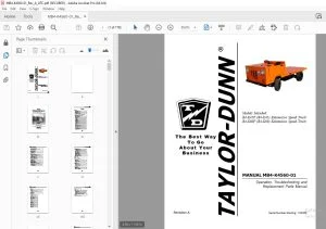
MP-250-02 Operation and Maintenance Manual with Parts List225
Model P 2-50 EE226
Table of Contents228
Important Information229
Section 1: Inspection, Safety and Introduction230
Section 3: Operating Instructions233
Section 4: Maintenance Guide Checklist239
Section 5: Lubrication Diagram240
Section 6: Trouble Shooting Procedures241
Section 7: Wiring Diagram243
Section 8: Parts Ordering Procedure244
Section 9: Suggested Spare Parts List245
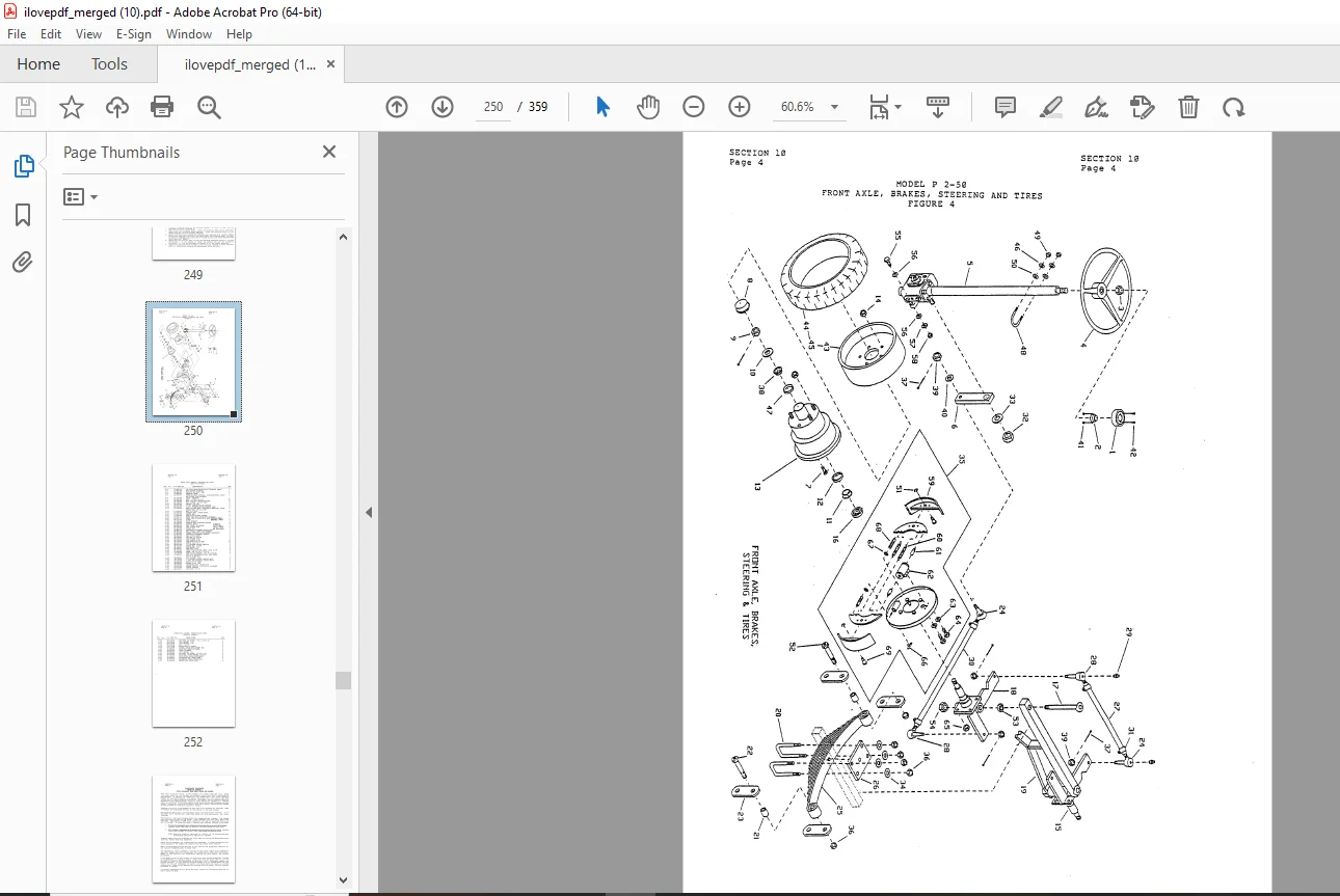
Section 10: Front Axle, Fork, Steering and Tires – Maintenance Procedures247
Section 11: “Full Floating” Rear Axle, Motor and Brakes – Maintenance Procedures253
Section 12: Electric Motors – Maintenance, Service and Adjustment264
Section 13: Hydraulic Brake System – Maintenance Procedures266
Section 14: Mechanical Control Linkage – Maintenance Procedures272
Section 15: EV-1 System and Instrument Panel275
Section 16: General Electrical Systems – Maintenance Procedures319
Section 17: Batteries and Chargers320
EV-1 Supplement329
Section 2: Module Setting by Vehicle329
Section 4: Wiring Diagrams330
Section 5: EV-1 Forward/Reverse Switch – Service and Adjustment335
Section 6: EV-1 SCR Control Accelerator Switch337
Section 7: 75-Ampere Electric Vehicle Control Contactors341
Section 8: 150- and 300- Ampere Electric Vehicle Control Contactors354
Section 9: EV-1 SCR Control Module – Diagram355
Section 10: Suggested Spare Parts List357
Section 11: General Electrical System – Parts Only359
DESCRIPTION:
Taylor-Dunn P 2-49 Operation & Maintenance Parts Manual S.NO.53151-814945 – PDF DOWNLOAD
OPERATING INSTRUCTIONS:
The controls on your Taylor-Dunn vehicle have been designed and located for convenience of operation and efficient performance. Before driving your vehicle for the first time, familiarize yourself with each of the controls. Read the following instructions and with power “OFF”, operate each control. By following this suggestion you will attain a “feel” for their operation prior to traveling under power for the first time.
- STEERING The steeriug wheel and steering system is similar to automotive types. Turn the steering wheel to the right (or clockwise) for a right turn and left (or counterclockwise) for a left turn.
- KEY LOCK Your vehicle is equipped with a keyed lock located in the designed to lock the switch in the neutral position only. from the lock in the locked position (neutral) only.
- BRAKE – AUTOMATIC (DEADMAN) dash panel. It is The key will remove The drivers seat operates the automatic “Deadman” brake. The weight of the person moves the seat down and operates the brake release linkage. The brake is automatically applied when the seat is vacated. In conjunction the power to the drive motor is disconnected as the brake is applied.
- BRAKE – (FOOT) The brake pedal is designed and located for right foot operation. It is the pedal located to the left of accelerator pedal. It functions the same as the brake pedal in your automobile. Depressing the pedal applies the braking action. The greater the effort applied to the pedal with your foot, the greater the braking action to your vehicle. Removing your foot from the pedal allows immediate release of the braking action to your vehicle.
- FORWARD-REVERSE SWITCH The forward-reverse switch is located on the steering column. It is operated by the handle. To place in forward position push the handle forward. To place in reverse position pull the handle backward towards rear
G.B 25/01/25